2007 INFINITI QX56 seat adjustment
[x] Cancel search: seat adjustmentPage 2684 of 3061

SE-12
< SERVICE INFORMATION >
AUTOMATIC DRIVE POSITIONER
NOTE:
• Disconnecting the battery erases the stored memory.
• After connecting the battery, insert the key into the ignition cylinder and turn the front door switch LH ON (open)→OFF (close)→ON
(open), the entry/exiting function becomes possible.
• After Exiting operation is carried out, return operation can be operated.
NOTE:
During automatic operation, if the ignition switch is turned ON→START, the automatic operation is suspended. When the ignition switch
returns to ON, it resumes.
FA I L - S A F E M O D E
When any manual and automatic operations are not performed, if any motor operations of seats or pedals are
detected for T2 or more, status is judged “Output error”.
CANCEL OF FAIL-SAFE MODE
The mode is cancelled when the A/T selector lever is shifted to P position from any other position.
NOTE:
The front seat LH position and pedal adjustment functions (see the following table) operate simultaneously in
the order of priority.
*: In conjunction with sliding the seat, the door mirrors are positioned.Function Description
Memory operation The front seat LH, steering wheel, pedals (accelerator, brake) and door mirrors move
to the stored driving position by pushing seat memory switch (1 or 2).
Entry/exit-
ing functionExiting operation At exit, the seat moves backward and the steering wheel raises. (Exiting position)
Entry operationAt entry, the seat and steering wheel return from exiting position to the previous driving
position before the exiting operation.
Keyfob interlock operationPerform memory operation, turnout operation and return operation by pressing keyfob
unlock button.
Auto operation temporary stop
conditions.When ignition switch is turned to START during seat memory switch operation and return
operation, seat memory switch operation and return operation is stopped.
Auto operation stop conditions.• When the vehicle speed becomes 7 km/h (4 MPH) or higher (memory switch operation
and entry operation).
• When the setting switch, seat memory switch 1, or 2 are pressed.
• When A/T selector lever is in any position other than P.
• When the door mirror remote control switch is operated (when ignition switch turned to
ON).
• When power seat switch turned ON.
• When pedal adjusting switch turned ON.
• When front seat sliding entry/exiting setting is OFF (entry/exiting operation).
OPERATED PORTION T2
Seat sliding Approx. 0.1 sec.
Seat reclining Same as above
Seat lifting (Front) Same as above
Seat lifting (Rear) Same as above
Steering wheel Same as above
Pedal adjust Same as above
Priority Function Priority Function
1 Seat sliding, (door mirror LH/RH)* 4 Seat reclining
2 Pedal 5 Seat lifter-FR
3 Steering wheel 6 Seat lifter-RR
Page 2704 of 3061

SE-32
< SERVICE INFORMATION >
AUTOMATIC DRIVE POSITIONER
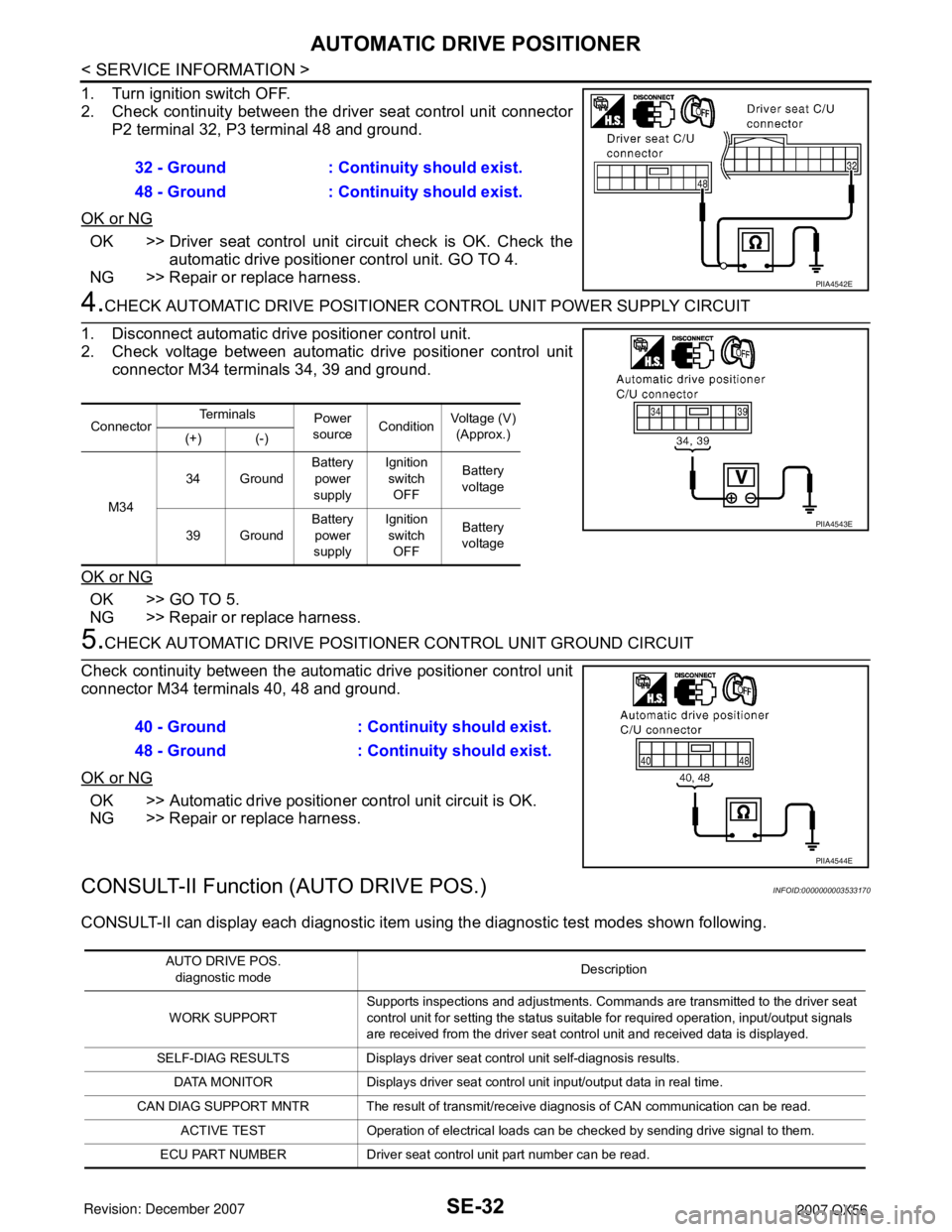
1. Turn ignition switch OFF.
2. Check continuity between the driver seat control unit connector
P2 terminal 32, P3 terminal 48 and ground.
OK or NG
OK >> Driver seat control unit circuit check is OK. Check the
automatic drive positioner control unit. GO TO 4.
NG >> Repair or replace harness.
4.CHECK AUTOMATIC DRIVE POSITIONER CONTROL UNIT POWER SUPPLY CIRCUIT
1. Disconnect automatic drive positioner control unit.
2. Check voltage between automatic drive positioner control unit
connector M34 terminals 34, 39 and ground.
OK or NG
OK >> GO TO 5.
NG >> Repair or replace harness.
5.CHECK AUTOMATIC DRIVE POSITIONER CONTROL UNIT GROUND CIRCUIT
Check continuity between the automatic drive positioner control unit
connector M34 terminals 40, 48 and ground.
OK or NG
OK >> Automatic drive positioner control unit circuit is OK.
NG >> Repair or replace harness.
CONSULT-II Function (AUTO DRIVE POS.)INFOID:0000000003533170
CONSULT-II can display each diagnostic item using the diagnostic test modes shown following. 32 - Ground : Continuity should exist.
48 - Ground : Continuity should exist.
PIIA4542E
ConnectorTe r m i n a l s
Power
sourceConditionVoltage (V)
(Approx.)
(+) (-)
M3434 GroundBattery
power
supplyIgnition
switch
OFFBattery
voltage
39 GroundBattery
power
supplyIgnition
switch
OFFBattery
voltage
PIIA4543E
40 - Ground : Continuity should exist.
48 - Ground : Continuity should exist.
PIIA4544E
AUTO DRIVE POS.
diagnostic modeDescription
WORK SUPPORTSupports inspections and adjustments. Commands are transmitted to the driver seat
control unit for setting the status suitable for required operation, input/output signals
are received from the driver seat control unit and received data is displayed.
SELF-DIAG RESULTS Displays driver seat control unit self-diagnosis results.
DATA MONITOR Displays driver seat control unit input/output data in real time.
CAN DIAG SUPPORT MNTR The result of transmit/receive diagnosis of CAN communication can be read.
ACTIVE TEST Operation of electrical loads can be checked by sending drive signal to them.
ECU PART NUMBER Driver seat control unit part number can be read.
Page 2825 of 3061

PRECAUTIONS
TF-3
< SERVICE INFORMATION >
C
E
F
G
H
I
J
K
L
MA
B
TF
N
O
P
SERVICE INFORMATION
PRECAUTIONS
Precaution for Supplemental Restraint System (SRS) "AIR BAG" and "SEAT BELT
PRE-TENSIONER"
INFOID:0000000003532506
The Supplemental Restraint System such as “AIR BAG” and “SEAT BELT PRE-TENSIONER”, used along
with a front seat belt, helps to reduce the risk or severity of injury to the driver and front passenger for certain
types of collision. This system includes seat belt switch inputs and dual stage front air bag modules. The SRS
system uses the seat belt switches to determine the front air bag deployment, and may only deploy one front
air bag, depending on the severity of a collision and whether the front occupants are belted or unbelted.
Information necessary to service the system safely is included in the SRS and SB section of this Service Man-
ual.
WARNING:
• To avoid rendering the SRS inoperative, which could increase the risk of personal injury or death in
the event of a collision which would result in air bag inflation, all maintenance must be performed by
an authorized NISSAN/INFINITI dealer.
• Improper maintenance, including incorrect removal and installation of the SRS, can lead to personal
injury caused by unintentional activation of the system. For removal of Spiral Cable and Air Bag
Module, see the SRS section.
• Do not use electrical test equipment on any circuit related to the SRS unless instructed to in this
Service Manual. SRS wiring harnesses can be identified by yellow and/or orange harnesses or har-
ness connectors.
Precaution for Transfer Assembly and Transfer Control Unit ReplacementINFOID:0000000003532507
When replacing transfer assembly or transfer control unit, check the 4WD shift indicator lamp as follows.
1. Turn ignition switch “ON”.
2. Check 4WD shift indicator lamp is turned ON for approx. 1 second.
• If OK, the position between transfer assembly and transfer control unit is correct.
• If NG, the position is different between transfer assembly and transfer control unit.
Adjust the position between transfer assembly and transfer control unit. Refer to "METHOD FOR POSITION
ADJUSTMENT".
METHOD FOR POSITION ADJUSTMENT
1. Start engine. Run the engine for at least 10 seconds.
2. Stop vehicle and move A/T selector lever to “N” position with brake pedal depressed. Stay in "N" for at
least 2 seconds.
3. Turn 4WD shift switch to “2WD” position. Stay in "2WD" for at least 2 seconds.
4. Turn ignition switch “OFF”.
5. Start engine.
6. Erase self-diagnosis. Refer to TF-42, "
CONSULT-II Function (ALL MODE AWD/4WD)" (with CONSULT-II)
or TF-48, "
Self-Diagnosis Procedure" (without CONSULT-II).
7. Check 4WD shift indicator lamp. Refer to TF-31, "
Inspections Before Trouble Diagnosis".
If 4WD shift indicator lamp does not indicate "2WD", install new transfer control unit and retry the above
check.
Page 3018 of 3061

WW-1
ELECTRICAL
C
D
E
F
G
H
I
J
L
M
SECTION WW
A
B
WW
N
O
P
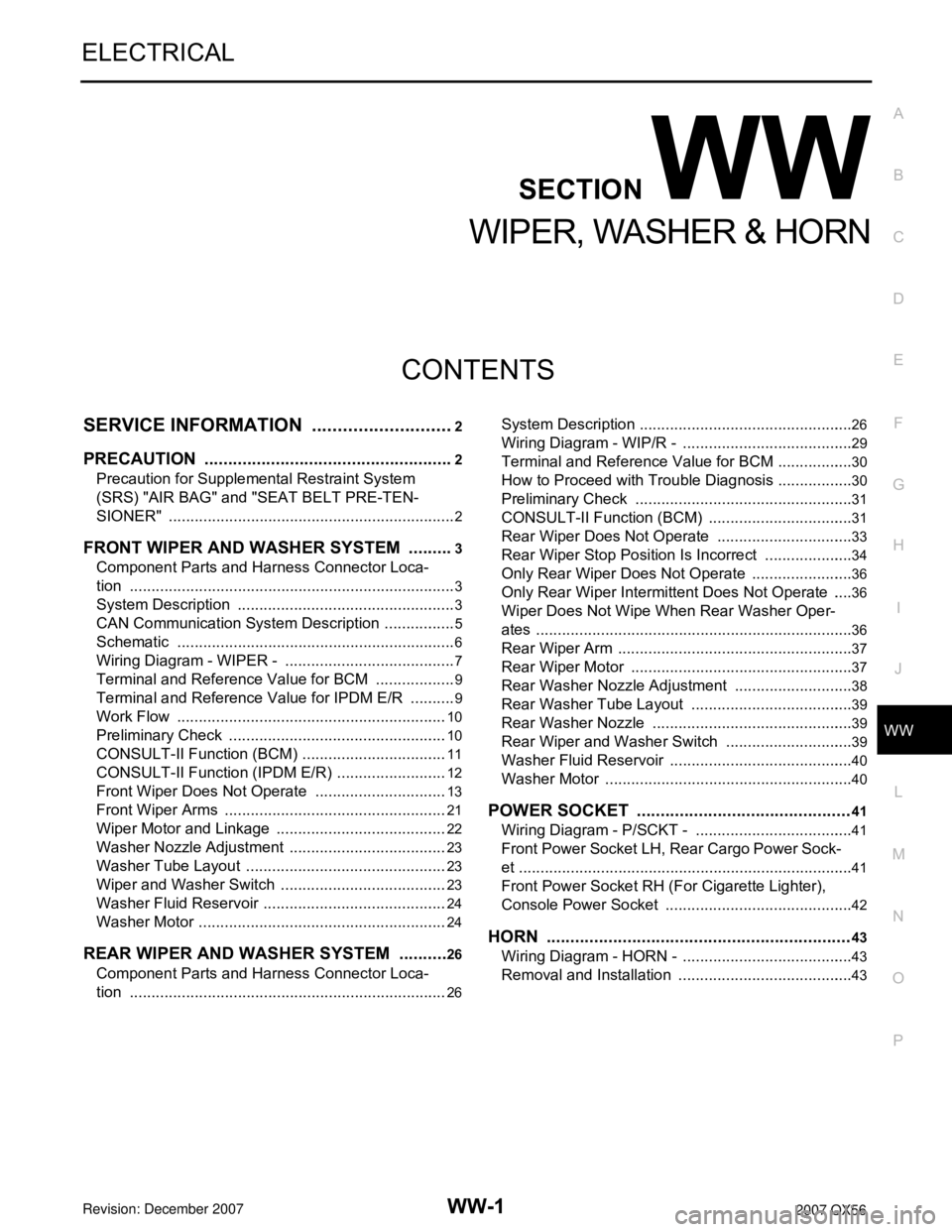
CONTENTS
WIPER, WASHER & HORN
SERVICE INFORMATION ............................2
PRECAUTION .....................................................2
Precaution for Supplemental Restraint System
(SRS) "AIR BAG" and "SEAT BELT PRE-TEN-
SIONER" ...................................................................
2
FRONT WIPER AND WASHER SYSTEM ..........3
Component Parts and Harness Connector Loca-
tion ............................................................................
3
System Description ...................................................3
CAN Communication System Description .................5
Schematic .................................................................6
Wiring Diagram - WIPER - ........................................7
Terminal and Reference Value for BCM ...................9
Terminal and Reference Value for IPDM E/R ...........9
Work Flow ...............................................................10
Preliminary Check ...................................................10
CONSULT-II Function (BCM) ..................................11
CONSULT-II Function (IPDM E/R) ..........................12
Front Wiper Does Not Operate ...............................13
Front Wiper Arms ....................................................21
Wiper Motor and Linkage ........................................22
Washer Nozzle Adjustment .....................................23
Washer Tube Layout ...............................................23
Wiper and Washer Switch .......................................23
Washer Fluid Reservoir ...........................................24
Washer Motor ..........................................................24
REAR WIPER AND WASHER SYSTEM ...........26
Component Parts and Harness Connector Loca-
tion ..........................................................................
26
System Description ..................................................26
Wiring Diagram - WIP/R - ........................................29
Terminal and Reference Value for BCM ..................30
How to Proceed with Trouble Diagnosis ..................30
Preliminary Check ...................................................31
CONSULT-II Function (BCM) ..................................31
Rear Wiper Does Not Operate ................................33
Rear Wiper Stop Position Is Incorrect .....................34
Only Rear Wiper Does Not Operate ........................36
Only Rear Wiper Intermittent Does Not Operate .....36
Wiper Does Not Wipe When Rear Washer Oper-
ates ..........................................................................
36
Rear Wiper Arm .......................................................37
Rear Wiper Motor ....................................................37
Rear Washer Nozzle Adjustment ............................38
Rear Washer Tube Layout ......................................39
Rear Washer Nozzle ...............................................39
Rear Wiper and Washer Switch ..............................39
Washer Fluid Reservoir ...........................................40
Washer Motor ..........................................................40
POWER SOCKET .............................................41
Wiring Diagram - P/SCKT - .....................................41
Front Power Socket LH, Rear Cargo Power Sock-
et ..............................................................................
41
Front Power Socket RH (For Cigarette Lighter),
Console Power Socket ............................................
42
HORN ................................................................43
Wiring Diagram - HORN - ........................................43
Removal and Installation .........................................43