Page 1413 of 3061
EC-330
< SERVICE INFORMATION >
DTC P0300 - P0308 MULTIPLE CYLINDER MISFIRE, NO. 1 - 8 CYLINDER MIS-
FIRE
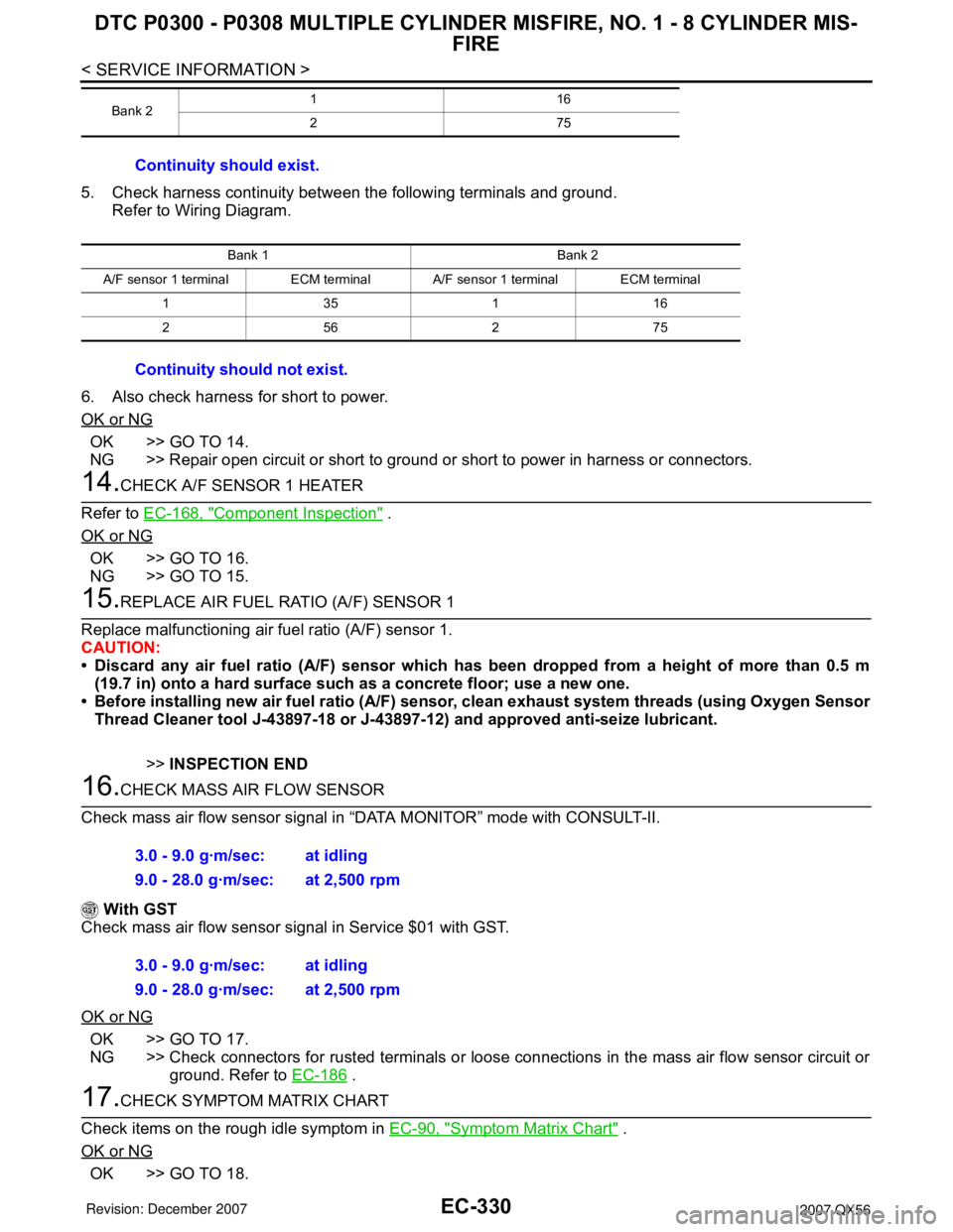
5. Check harness continuity between the following terminals and ground.
Refer to Wiring Diagram.
6. Also check harness for short to power.
OK or NG
OK >> GO TO 14.
NG >> Repair open circuit or short to ground or short to power in harness or connectors.
14.CHECK A/F SENSOR 1 HEATER
Refer to EC-168, "
Component Inspection" .
OK or NG
OK >> GO TO 16.
NG >> GO TO 15.
15.REPLACE AIR FUEL RATIO (A/F) SENSOR 1
Replace malfunctioning air fuel ratio (A/F) sensor 1.
CAUTION:
• Discard any air fuel ratio (A/F) sensor which has been dropped from a height of more than 0.5 m
(19.7 in) onto a hard surface such as a concrete floor; use a new one.
• Before installing new air fuel ratio (A/F) sensor, clean exhaust system threads (using Oxygen Sensor
Thread Cleaner tool J-43897-18 or J-43897-12) and approved anti-seize lubricant.
>>INSPECTION END
16.CHECK MASS AIR FLOW SENSOR
Check mass air flow sensor signal in “DATA MONITOR” mode with CONSULT-II.
With GST
Check mass air flow sensor signal in Service $01 with GST.
OK or NG
OK >> GO TO 17.
NG >> Check connectors for rusted terminals or loose connections in the mass air flow sensor circuit or
ground. Refer to EC-186
.
17.CHECK SYMPTOM MATRIX CHART
Check items on the rough idle symptom in EC-90, "
Symptom Matrix Chart" .
OK or NG
OK >> GO TO 18.
Bank 2116
275
Continuity should exist.
Bank 1 Bank 2
A/F sensor 1 terminal ECM terminal A/F sensor 1 terminal ECM terminal
135116
256275
Continuity should not exist.
3.0 - 9.0 g·m/sec: at idling
9.0 - 28.0 g·m/sec: at 2,500 rpm
3.0 - 9.0 g·m/sec: at idling
9.0 - 28.0 g·m/sec: at 2,500 rpm
Page 1679 of 3061
EC-596
< SERVICE INFORMATION >
DTC P2A00, P2A03 A/F SENSOR 1
OK >> GO TO 10.
NG >> GO TO 11.
10.CHECK INTERMITTENT INCIDENT
Perform EC-138
.
OK or NG
OK >> GO TO 11.
NG >> Repair or replace.
11 .REPLACE AIR FUEL RATIO (A/F) SENSOR 1
Replace malfunctioning air fuel ratio (A/F) sensor 1.
CAUTION:
• Discard any A/F sensor which has been dropped from a height of more than 0.5 m (19.7 in) onto a
hard surface such as a concrete floor; use a new one.
• Before installing new A/F sensor, clean exhaust system threads using Oxygen Sensor Thread
Cleaner tool J-43897-18 or J-43897-12 and approved anti-seize lubricant.
>> GO TO 12.
12.CONFIRM A/F ADJUSTMENT DATA
1. Turn ignition switch OFF and then ON.
2. Select “A/F ADJ-B1” and “A/F ADJ-B2” in “DATA MONITOR”
mode with CONSULT-II.
3. Make sure that “0.000” is displayed on CONSULT-II screen.
>>INSPECTION END
Removal and InstallationINFOID:0000000003532147
AIR FUEL RATIO (A/F) SENSOR 1
Refer toEM-21.
PBIB3202E
Page 1820 of 3061
EM-50
< SERVICE INFORMATION >
CAMSHAFT
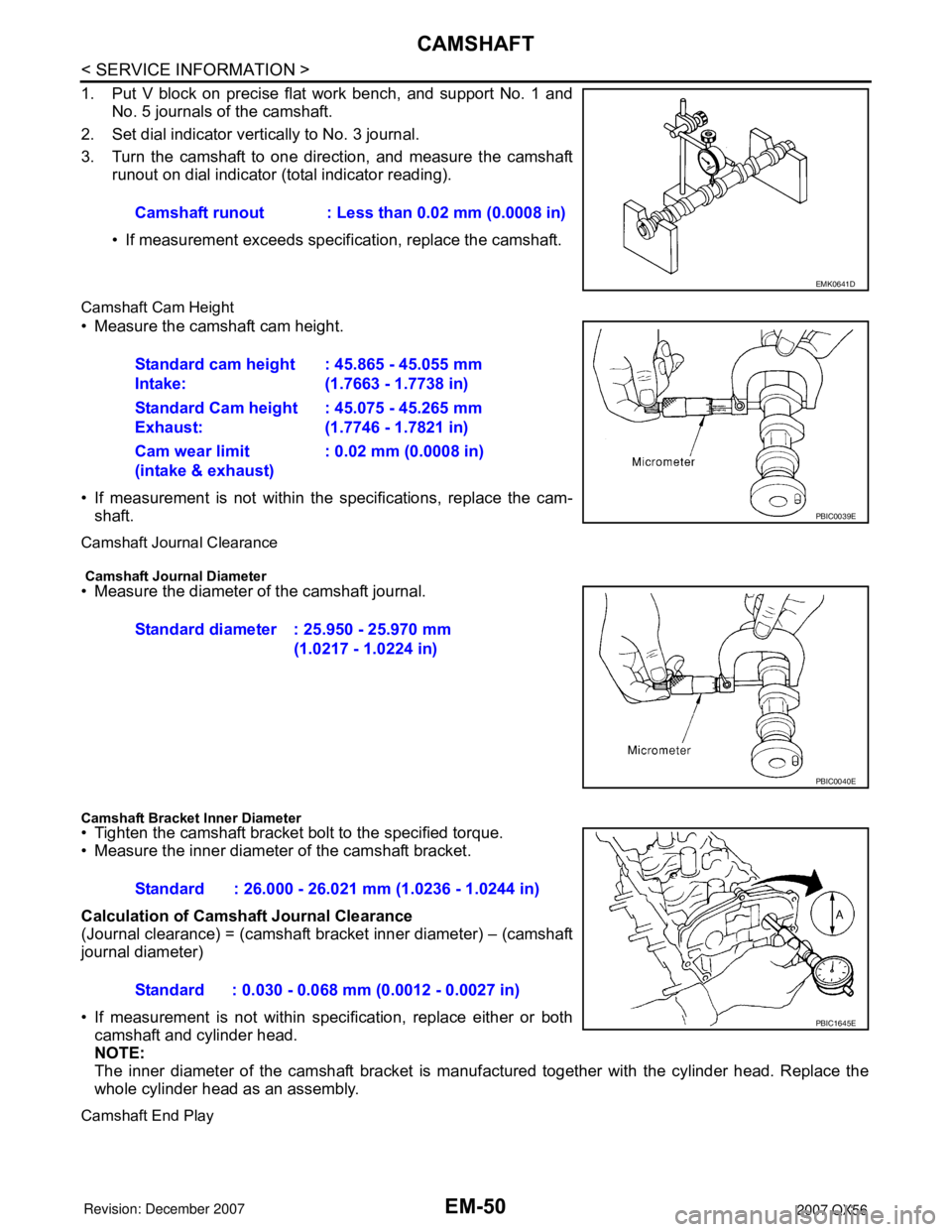
1. Put V block on precise flat work bench, and support No. 1 andNo. 5 journals of the camshaft.
2. Set dial indicator vertically to No. 3 journal.
3. Turn the camshaft to one direction, and measure the camshaft runout on dial indicator (total indicator reading).
• If measurement exceeds specif ication, replace the camshaft.
Camshaft Cam Height
• Measure the camshaft cam height.
• If measurement is not within the specifications, replace the cam-
shaft.
Camshaft Journal Clearance
Camshaft Journal Diameter• Measure the diameter of the camshaft journal.
Camshaft Bracket Inner Diameter• Tighten the camshaft bracket bolt to the specified torque.
• Measure the inner diameter of the camshaft bracket.
Calculation of Camshaft Journal Clearance
(Journal clearance) = (camshaft bracket inner diameter) – (camshaft
journal diameter)
• If measurement is not within spec ification, replace either or both
camshaft and cylinder head.
NOTE:
The inner diameter of the camshaft bracket is manuf actured together with the cylinder head. Replace the
whole cylinder head as an assembly.
Camshaft End Play
Camshaft runout : Less than 0.02 mm (0.0008 in)
EMK0641D
Standard cam height
Intake: : 45.865 - 45.055 mm
(1.7663 - 1.7738 in)
Standard Cam height
Exhaust: : 45.075 - 45.265 mm
(1.7746 - 1.7821 in)
Cam wear limit
(intake & exhaust) : 0.02 mm (0.0008 in)
PBIC0039E
Standard diameter : 25.950 - 25.970 mm
(1.0217 - 1.0224 in)
PBIC0040E
Standard : 26.000 - 26.021 mm (1.0236 - 1.0244 in)
Standard : 0.030 - 0.068 mm (0.0012 - 0.0027 in)
PBIC1645E
Page 1831 of 3061
OIL SEALEM-61
< SERVICE INFORMATION >
C
DE
F
G H
I
J
K L
M A
EM
NP
O
OIL SEAL
Removal and Installation of Valve Oil SealINFOID:0000000003531537
REMOVAL
1. Remove the camshaft relating to the valve oil seal to be removed. Refer to
EM-46, "Removal and Installa-
tion".
2. Remove the valve lifters. Refer to EM-65, "
Removal and Installation".
• Correctly identify the location where each part is removed from. Keep parts organized to avoid mixing
them up.
3. Turn the crankshaft until the cylinder requiring new oil seals is at TDC. This will prevent the valve from
dropping into the cylinder.
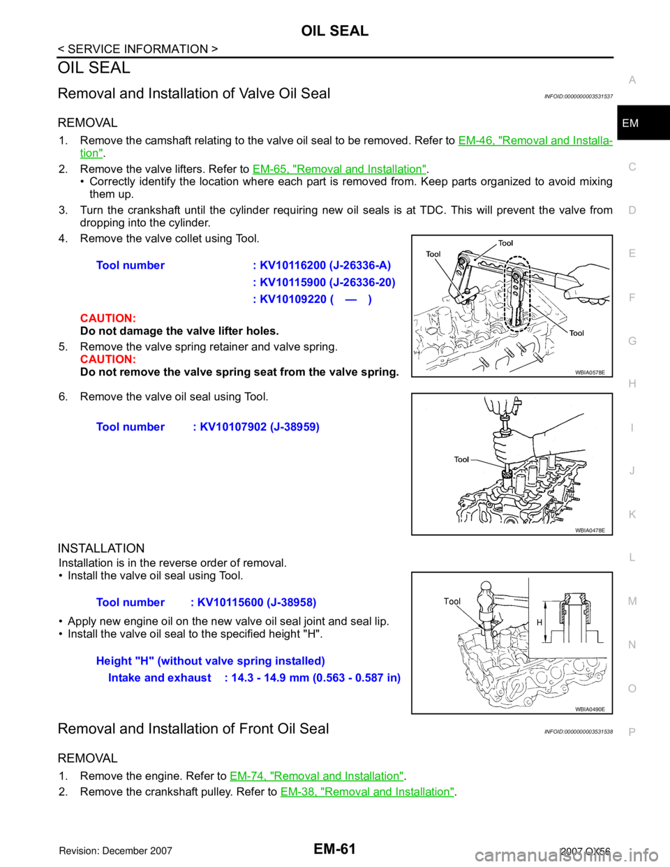
4. Remove the valve collet using Tool.
CAUTION:
Do not damage the valve lifter holes.
5. Remove the valve spring retainer and valve spring. CAUTION:
Do not remove the valve spring seat from the valve spring.
6. Remove the valve oil seal using Tool.
INSTALLATION
Installation is in the reverse order of removal.
• Install the valve oil seal using Tool.
• Apply new engine oil on the new valve oil seal joint and seal lip.
• Install the valve oil seal to the specified height "H".
Removal and Installati on of Front Oil SealINFOID:0000000003531538
REMOVAL
1. Remove the engine. Refer to EM-74, "Removal and Installation".
2. Remove the crankshaft pulley. Refer to EM-38, "
Removal and Installation".
Tool number : KV10116200 (J-26336-A)
: KV10115900 (J-26336-20)
: KV10109220 ( — )
WBIA0578E
Tool number : KV10107902 (J-38959)
WBIA0478E
Tool number : KV10115600 (J-38958)
Height "H" (without valve spring installed)Intake and exhaust : 14.3 - 14.9 mm (0.563 - 0.587 in)
WBIA0490E
Page 1832 of 3061
EM-62
< SERVICE INFORMATION >
OIL SEAL
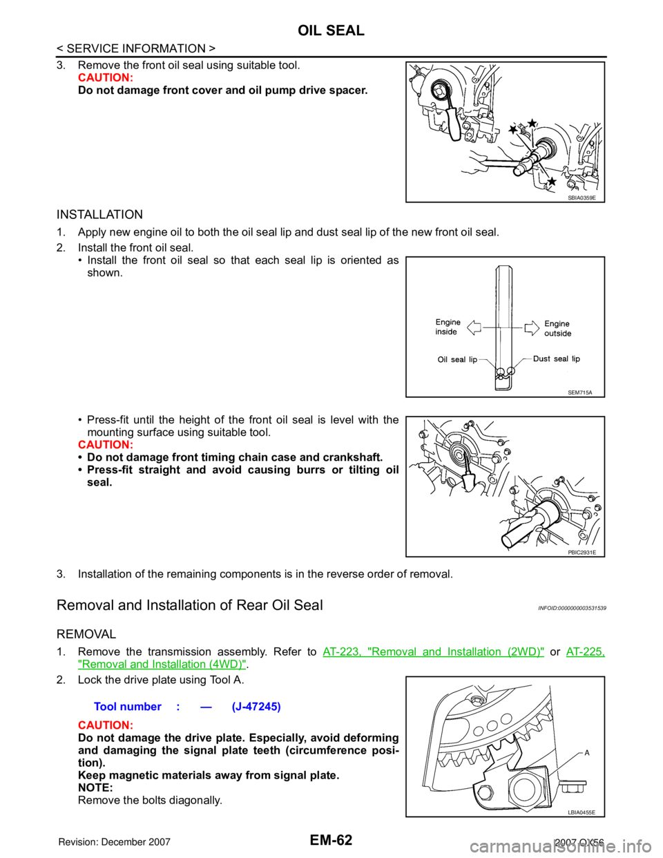
3. Remove the front oil seal using suitable tool.CAUTION:
Do not damage front cover and oil pump drive spacer.
INSTALLATION
1. Apply new engine oil to both the oil seal lip and dust seal lip of the new front oil seal.
2. Install the front oil seal.• Install the front oil seal so that each seal lip is oriented as
shown.
• Press-fit until the height of the front oil seal is level with the mounting surface using suitable tool.
CAUTION:
• Do not damage front timing chain case and crankshaft.
• Press-fit straight and avoid causing burrs or tilting oil
seal.
3. Installation of the remaining components is in the reverse order of removal.
Removal and Installation of Rear Oil SealINFOID:0000000003531539
REMOVAL
1. Remove the transmission assembly. Refer to AT-223, "Removal and Installation (2WD)" or AT-225,
"Removal and Installation (4WD)".
2. Lock the drive plate using Tool A.
CAUTION:
Do not damage the drive plat e. Especially, avoid deforming
and damaging the signal plat e teeth (circumference posi-
tion).
Keep magnetic materials away from signal plate.
NOTE:
Remove the bolts diagonally.
SBIA0359E
SEM715A
PBIC2931E
Tool number : — (J-47245)
LBIA0455E
Page 1838 of 3061
EM-68
< SERVICE INFORMATION >
CYLINDER HEAD
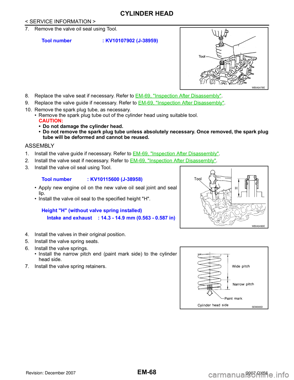
7. Remove the valve oil seal using Tool.
8. Replace the valve seat if necessary. Refer to EM-69, "
Inspection After Disassembly".
9. Replace the valve guide if necessary. Refer to EM-69, "
Inspection After Disassembly".
10. Remove the spark plug tube, as necessary.
• Remove the spark plug tube out of the cylinder head using suitable tool.
CAUTION:
• Do not damage the cylinder head.
• Do not remove the spark plug tube unless absolutely necessary. Once removed, the spark plug
tube will be deformed and cannot be reused.
ASSEMBLY
1. Install the valve guide if necessary. Refer to EM-69, "Inspection After Disassembly".
2. Install the valve seat if necessary. Refer to EM-69, "
Inspection After Disassembly".
3. Install the valve oil seal using Tool.
• Apply new engine oil on the new valve oil seal joint and seal
lip.
• Install the valve oil seal to the specified height "H".
4. Install the valves in their original position.
5. Install the valve spring seats.
6. Install the valve springs.
• Install the narrow pitch end (paint mark side) to the cylinder
head side.
7. Install the valve spring retainers.Tool number : KV10107902 (J-38959)
WBIA0478E
Tool number : KV10115600 (J-38958)
Height "H" (without valve spring installed)
Intake and exhaust : 14.3 - 14.9 mm (0.563 - 0.587 in)
WBIA0490E
SEM085D
Page 1839 of 3061
CYLINDER HEAD
EM-69
< SERVICE INFORMATION >
C
D
E
F
G
H
I
J
K
L
MA
EM
N
P O
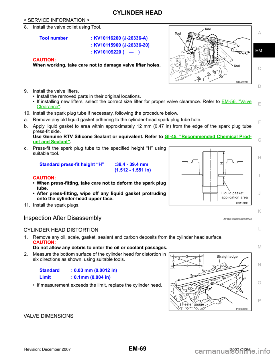
8. Install the valve collet using Tool.
CAUTION:
When working, take care not to damage valve lifter holes.
9. Install the valve lifters.
• Install the removed parts in their original locations.
• If installing new lifters, select the correct size lifter for proper valve clearance. Refer to EM-56, "
Va l v e
Clearance".
10. Install the spark plug tube if necessary, following the procedure below.
a. Remove any old liquid gasket adhering to the cylinder-head spark plug tube hole.
b. Apply liquid gasket to area within approximately 12 mm (0.47 in) from the edge of the spark plug tube
press-fit side.
Use Genuine RTV Silicone Sealant or equivalent. Refer to GI-45, "
Recommended Chemical Prod-
uct and Sealant".
c. Press-fit the spark plug tube to the specified height “H” using
suitable tool.
CAUTION:
• When press-fitting, take care not to deform the spark plug
tube.
• After press-fitting, wipe off any liquid gasket protruding
onto the cylinder-head upper face.
11. Install the spark plugs.
Inspection After DisassemblyINFOID:0000000003531543
CYLINDER HEAD DISTORTION
1. Remove any oil, scale, gasket, sealant and carbon deposits from the cylinder head surface.
CAUTION:
Do not allow any debris to enter the oil or coolant passages.
2. Measure the bottom surface of the cylinder head for distortion in
six directions as shown, using suitable tools.
• If measurement exceeds the limit, replace the cylinder head.
VALVE DIMENSIONS
Tool number : KV10116200 (J-26336-A)
: KV10115900 (J-26336-20)
: KV10109220 ( — )
WBIA0578E
Standard press-fit height “H” :38.4 - 39.4 mm
(1.512 - 1.551 in)
KBIA1248E
Standard : 0.03 mm (0.0012 in)
Limit : 0.1mm (0.004 in)
PBIC0075E
Page 1843 of 3061
CYLINDER HEAD
EM-73
< SERVICE INFORMATION >
C
D
E
F
G
H
I
J
K
L
MA
EM
N
P O
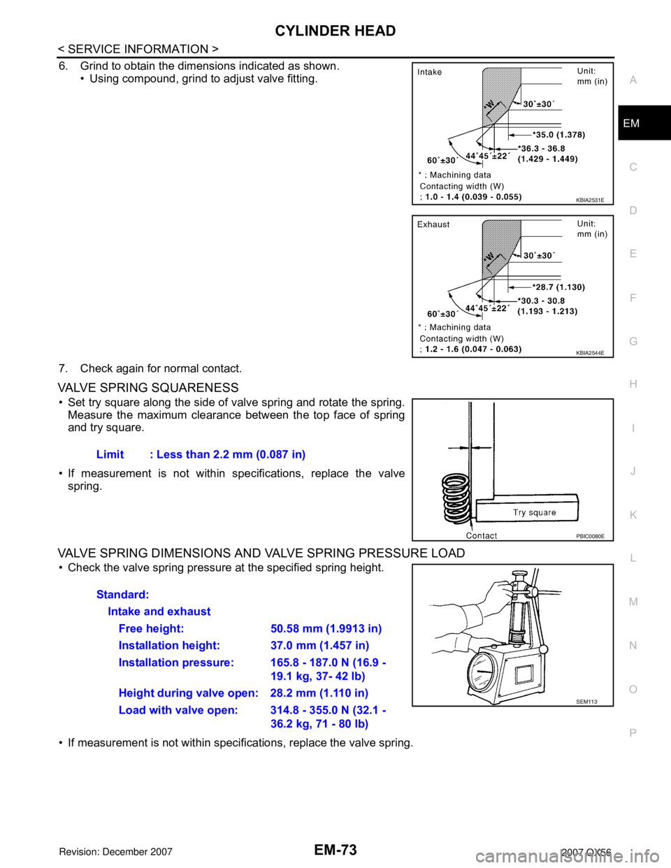
6. Grind to obtain the dimensions indicated as shown.
• Using compound, grind to adjust valve fitting.
7. Check again for normal contact.
VALVE SPRING SQUARENESS
• Set try square along the side of valve spring and rotate the spring.
Measure the maximum clearance between the top face of spring
and try square.
• If measurement is not within specifications, replace the valve
spring.
VALVE SPRING DIMENSIONS AND VALVE SPRING PRESSURE LOAD
• Check the valve spring pressure at the specified spring height.
• If measurement is not within specifications, replace the valve spring.
KBIA2531E
KBIA2544E
Limit : Less than 2.2 mm (0.087 in)
PBIC0080E
Standard:
Intake and exhaust
Free height: 50.58 mm (1.9913 in)
Installation height: 37.0 mm (1.457 in)
Installation pressure: 165.8 - 187.0 N (16.9 -
19.1 kg, 37- 42 lb)
Height during valve open: 28.2 mm (1.110 in)
Load with valve open: 314.8 - 355.0 N (32.1 -
36.2 kg, 71 - 80 lb)
SEM113