Page 725 of 3061
BL-14
< SERVICE INFORMATION >
HOOD
4. Install the primary and secondary cables securely to the hood
lock.
5. Install the hood lock and the secondary hood lock release
assemblies.
6. Check the hood lock adjustment and hood opener operation.
Refer to BL-11, "
Fitting Adjustment".
Hood Lock Control InspectionINFOID:0000000003532894
CAUTION:
If the hood lock cable is bent or deformed, replace it.
1. Remove the front grille. Refer to EI-16
.
2. Make sure the secondary latch is properly engaged with the sec-
ondary striker with hood's own weight by dropping it from
approx. 200 mm (7.87 in) height.
3. While operating the hood opener, carefully make sure the front
end of the hood is raised by approx. 20 mm (0.79 in). Also make
sure the hood opener returns to the original position.
4. Check the hood lock lubrication condition. If necessary, apply
“body grease” to the points shown in the figure.
5. Install the front grille. Refer to EI-16
.
PIIA0174E
PIIA1086E
PIIA0176E
Page 817 of 3061
BL-106
< SERVICE INFORMATION >
DOOR
DOOR
Fitting AdjustmentINFOID:0000000003532977
Front door
Longitudinal clearance and surface height adjustment at front end
1. Remove the fender. Refer to EI-19.
2. Loosen the hinge bolts. Raise the front door at rear end to adjust.
3. Install the fender. Refer to EI-19
.
Rear door
Longitudinal clearance and surface height adjustment at front end
1. Loosen the bolts. Open the rear door, and raise the rear door at rear end to adjust.
Striker adjustment
D. 4.5 ± 1.0 mm (0.177 ± 0.039 in)
AWKIA0675ZZ
Page 901 of 3061
PREPARATION
BR-3
< SERVICE INFORMATION >
C
D
E
G
H
I
J
K
L
MA
B
BR
N
O
P
PREPARATION
Special Service ToolINFOID:0000000003532719
The actual shapes of Kent-Moore tools may differ from those of special service tools illustrated here.
Commercial Service ToolINFOID:0000000003532720
Tool number
(Kent-Moore No.)
Tool nameDescription
—
(J-46532)
Brake and clutch pedal height measure-
ment toolMeasuring brake pedal height
LFIA0227E
Tool nameDescription
1. Flare nut crowfoot
2. Torque wrenchRemoving and installing each brake pip-
ing.
a: 10 mm (0.39 in) / 12 mm (0.47 in)
Power toolRemoving nuts, bolts and screws.
S-NT360
PBIC0190E
PBIC0191E
Page 903 of 3061
BRAKE PEDAL
BR-5
< SERVICE INFORMATION >
C
D
E
G
H
I
J
K
L
MA
B
BR
N
O
P
BRAKE PEDAL
Inspection and AdjustmentINFOID:0000000003532722
INSPECTION
1. Inspect the brake pedal free height "H" from the lower dash panel using tool.
2. Adjust the height referring to the following specifications.
CAUTION:
When equipped with adjustable pedal, the pedal must be in
the forwardmost (closest to the floor) position for pedal
height measurement.
Brake Pedal Specifications
Unit: mm (in)
ADJUSTMENT
1. Loosen the stop lamp switch and ASCD switch by turning 45° counterclockwise. Tool number : — (J-46532)
WFIA0160E
Free height "H" : 182.3 - 192.3 mm (7.18 - 7.57 in)
Depressed pedal height "D" [under a force of 490 N (50 kg-f, 110 lb-f) with engine
running]: More than 90.3 mm (3.55 in)
Clearance between pedal stopper and threaded end of stop lamp switch and
ASCD switch "C
1 " or “C2 ”: 0.74 - 1.96 mm (0.029 - 0.077 in)
Pedal play "A" : 3 - 11 mm (0.12 - 0.43 in)
Page 904 of 3061

BR-6
< SERVICE INFORMATION >
BRAKE PEDAL
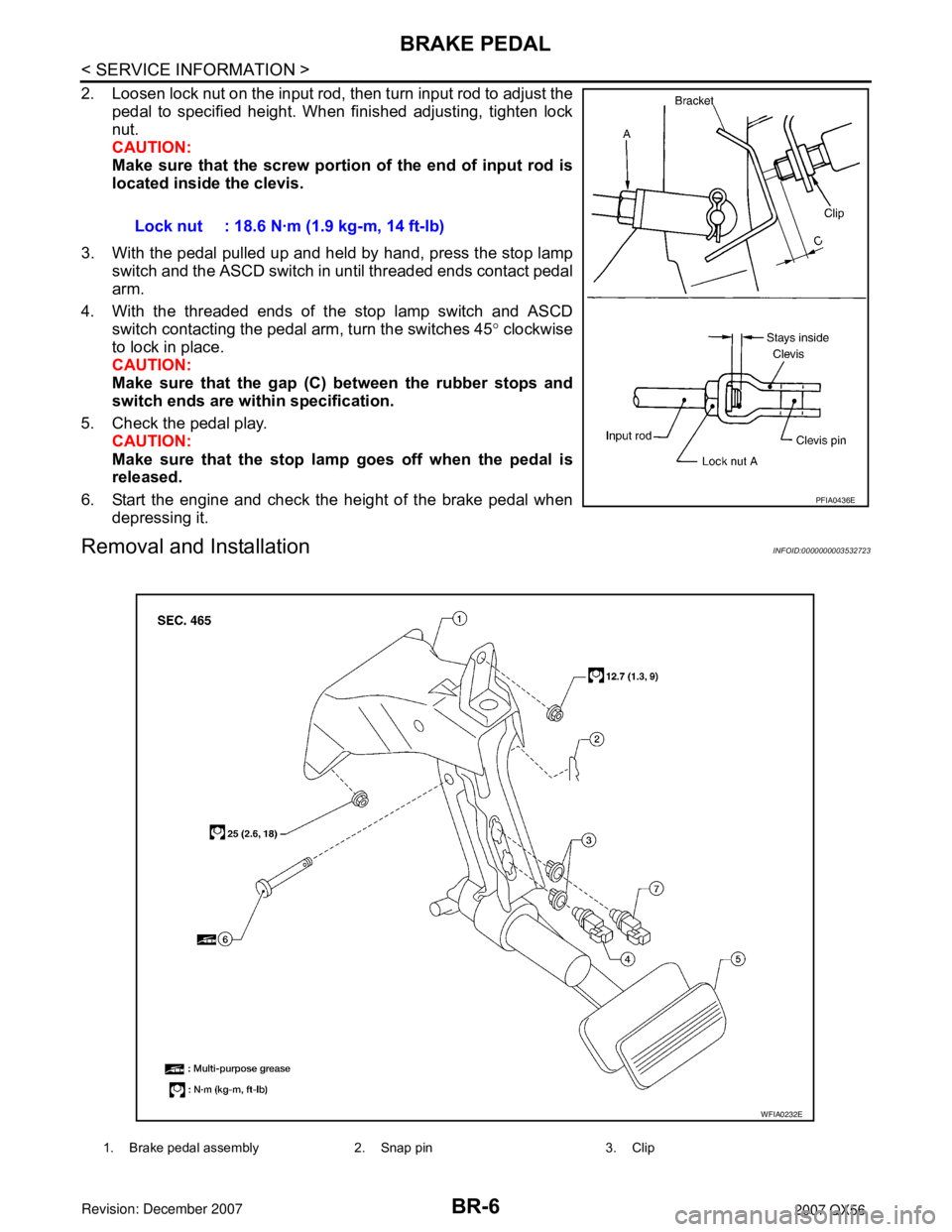
2. Loosen lock nut on the input rod, then turn input rod to adjust the
pedal to specified height. When finished adjusting, tighten lock
nut.
CAUTION:
Make sure that the screw portion of the end of input rod is
located inside the clevis.
3. With the pedal pulled up and held by hand, press the stop lamp
switch and the ASCD switch in until threaded ends contact pedal
arm.
4. With the threaded ends of the stop lamp switch and ASCD
switch contacting the pedal arm, turn the switches 45° clockwise
to lock in place.
CAUTION:
Make sure that the gap (C) between the rubber stops and
switch ends are within specification.
5. Check the pedal play.
CAUTION:
Make sure that the stop lamp goes off when the pedal is
released.
6. Start the engine and check the height of the brake pedal when
depressing it.
Removal and InstallationINFOID:0000000003532723
Lock nut : 18.6 N·m (1.9 kg-m, 14 ft-lb)
PFIA0436E
1. Brake pedal assembly 2. Snap pin 3. Clip
WFIA0232E
Page 914 of 3061

BR-16
< SERVICE INFORMATION >
BRAKE BOOSTER
• Be careful not to damage brake booster stud bolt threads. If brake booster is tilted or inclined during
installation, dash panel may damage the threads.
• Attach the check valve in the correct direction.
1. Remove engine room cover with power tool. Refer to EM-12, "
Removal and Installation" .
2. Remove engine air duct assembly. Refer to EM-15, "
Removal and Installation" .
3. Remove brake piping from brake master cylinder.
4. Remove brake master cylinder. Refer to BR-13, "
Removal and Installation" .
5. Remove vacuum hose from brake booster. Refer to BR-17
.
6. Disconnect active boost and delta stroke sensor harness connectors from brake booster assembly.
7. Remove brake pedal attachment snap pin and clevis pin from inside the vehicle.
8. Remove nuts on brake booster and brake pedal assembly.
9. Remove brake booster assembly from dash panel.
INSPECTION AFTER REMOVAL
Output Rod Length Inspection
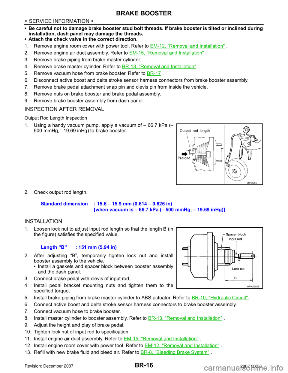
1. Using a handy vacuum pump, apply a vacuum of – 66.7 kPa (–
500 mmHg, –19.69 inHg) to brake booster.
2. Check output rod length.
INSTALLATION
1. Loosen lock nut to adjust input rod length so that the length B (in
the figure) satisfies the specified value.
2. After adjusting “B”, temporarily tighten lock nut and install
booster assembly to the vehicle.
• Install a gaskets and spacer block between booster assembly
and the dash panel.
3. Connect brake pedal with clevis of input rod.
4. Install pedal bracket mounting nuts and tighten them to the
specified torque.
5. Install brake piping from brake master cylinder to ABS actuator. Refer to BR-10, "
Hydraulic Circuit".
6. Connect active boost and delta stroke sensor harness connectors to brake booster assembly.
7. Connect vacuum hose to brake booster.
8. Install master cylinder to booster assembly. Refer to BR-13, "
Removal and Installation" .
9. Adjust the height and play of brake pedal.
10. Tighten lock nut of input rod to specification.
11. Install engine air duct assembly. Refer to EM-15, "
Removal and Installation" .
12. Install engine room cover with power tool. Refer to EM-12, "
Removal and Installation" .
13. Refill with new brake fluid and bleed air. Refer to BR-8, "
Bleeding Brake System" .
SBR208E
Standard dimension : 15.6 − 15.9 mm (0.614 − 0.626 in)
[when vacuum is – 66.7 kPa (– 500 mmHg, – 19.69 inHg)]
Length “B” : 151 mm (5.94 in)
WFIA0382E
Page 927 of 3061

SERVICE DATA AND SPECIFICATIONS (SDS)
BR-29
< SERVICE INFORMATION >
C
D
E
G
H
I
J
K
L
MA
B
BR
N
O
P
SERVICE DATA AND SPECIFICATIONS (SDS)
General SpecificationINFOID:0000000003532748
Unit: mm (in)
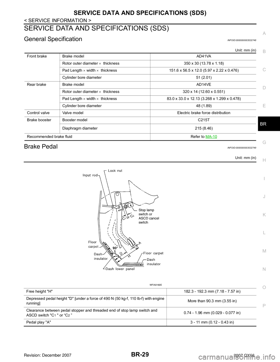
Brake PedalINFOID:0000000003532749
Unit: mm (in)
Front brake Brake model AD41VA
Rotor outer diameter × thickness 350 x 30 (13.78 x 1.18)
Pad Length × width × thickness 151.6 x 56.5 x 12.0 (5.97 x 2.22 x 0.476)
Cylinder bore diameter 51 (2.01)
Rear brake Brake model AD14VE
Rotor outer diameter × thickness 320 x 14 (12.60 x 0.551)
Pad Length × width × thickness 83.0 x 33.0 x 12.13 (3.268 x 1.299 x 0.478)
Cylinder bore diameter 48 (1.89)
Control valve Valve model Electric brake force distribution
Brake booster Booster model C215T
Diaphragm diameter 215 (8.46)
Recommended brake fluid Refer to MA-10
Free height "H"182.3 - 192.3 mm (7.18 - 7.57 in)
Depressed pedal height "D" [under a force of 490 N (50 kg-f, 110 lb-f) with engine
running]More than 90.3 mm (3.55 in)
Clearance between pedal stopper and threaded end of stop lamp switch and
ASCD switch "C
1 " or “C2 ”0.74 - 1.96 mm (0.029 - 0.077 in)
Pedal play "A"3 - 11 mm (0.12 - 0.43 in)
WFIA0160E
Page 1252 of 3061
DTC P0031, P0032, P0051, P0052 A/F SENSOR 1 HEATER
EC-169
< SERVICE INFORMATION >
C
D
E
F
G
H
I
J
K
L
MA
EC
N
P O
1. Check resistance between A/F sensor 1 terminals as follows.
2. If NG, replace air fuel ratio (A/F) sensor 1.
CAUTION:
• Discard any A/F sensor which has been dropped from a
height of more than 0.5 m (19.7 in) onto a hard surface such
as a concrete floor; use a new one.
• Before installing new A/F sensor, clean exhaust system
threads using Heated Oxygen Sensor Thread Cleaner tool J-
43897-18 or J-43897-12 and approved anti-seize lubricant.
Removal and InstallationINFOID:0000000003531663
AIR FUEL RATIO SENSOR HEATER
Refer to EM-21.
Terminal No. Resistance
3 and 4 1.8 - 2.44 Ω [at 25°C (77°F)]
3 and 1, 2
∞ Ω
(Continuity should not exist)
4 and 1, 2
PBIB3309E