2007 INFINITI QX56 fuel
[x] Cancel search: fuelPage 2110 of 3061

IDX-6
ALPHABETICAL INDEX
Line pressure solenoid valve ........................... AT-118
Line pressure switch (Transfer) .......... TF-154, TF-167
Line pressure test (A/T) ..................................... AT-52
Location of electrical units ................................. PG-65
Low coast brake solenoid valve ......... AT-151, AT-153
Low tire pressure warning system ...................... WT-8
Low tire pressure warning system - trouble diagnoses .
WT-11
Low tire pressure warning system - Wiring diagram .....
WT-11
Lubricant (R134a) A/C ..................................... ATC-22
Lubricants ......................................................... MA-11
Lubrication circuit (engine) ................................... LU-6
Lubrication oil A/C ............................................ ATC-22
Lubrication-locks, hinges and hood latches ...... MA-31
M
MAFS - Wiring diagram ..................... EC-200
, EC-208
Magnet clutch ............................... ATC-115, ATC-180
MAIN - Wiring diagram ...................... EC-150, AT-163
Main oil pump (Transfer) ..................... TF-154, TF-167
Mainshaft (Transfer) ........................... TF-154, TF-167
Maintenance (engine)Schedule 1 ....................... MA-7
Maintenance (engine)Schedule 2 ....................... MA-9
Major overhaul (Final drive) ............................. FFD-14
Major overhaul (Transfer) ................................ TF-146
Malfunction indicator lamp (MIL) ........................ EC-65
Map lamp .......................................................... LT-111
Mass air flow sensor (MAFS) ............. EC-197, EC-206
Meter ..................................................................... DI-5
METER - Wiring diagram ...................................... DI-9
MIL data link connectors circuit ....................... EC-697
MIL/DL - Wiring diagram .................................. EC-697
MIRROR - Wiring diagram ................................ GW-87
Misfire .............................................................. EC-350
Mode door control linkage adjustment ............. ATC-65
Mode door motor ............................ ATC-62, ATC-165
Model variation ................................................... GI-48
Multiport fuel injection (MFI) system .................. EC-25
Multiport fuel injection precautions ....................... GI-6
Multi-remote control system - See Remote keyless entry
system ............................................................... BL-40
N
NATS - Wiring diagram .................................... BL-130
NAVI - Wiring diagram ....................................... AV-86
NAVI Control Unit .............................................. AV-83
Navigation system ............................................. AV-81
Neutral-4LO switch ............................................ TF-61
NONDTC - Wiring diagram .............................. AT-172
NVH troubleshooting (AX) ................................. FAX-4
NVH troubleshooting (EM) ................................ EM-10
NVH troubleshooting (Final drive) ..................... RFD-7
NVH troubleshooting (Propeller shaft) ................. PR-3
NVH troubleshooting (RAX) .............................. RAX-4
NVH troubleshooting (RSU) .............................. RSU-5
NVH troubleshooting (ST) .................................... PS-5
NVH troubleshooting (Transfer) ......................... TF-10
NVH troubleshooting (WT)NVH troubleshooting (WT) ..
WT-4
NVIS (Nissan vehicle immobilizer system) precautions
GI-3
O
O2H2B1 - Wiring diagram ............................... EC-183
O2H2B2 - Wiring diagram ............................... EC-185
O2S2B1 - Wiring diagram ... EC-279, EC-290, EC-303
O2S2B2 - Wiring diagram ... EC-281, EC-292, EC-305
Oil cooler (engine) .............................................. LU-12
Oil filter ............................................................... LU-11
Oil filter (Transfer) ............................................ TF-143
Oil pan (engine) ................................................ EM-24
Oil pressure (engine) ........................................... LU-8
Oil pressure relief valve (engine) ......................... LU-6
Oil pump (engine) .............................................. LU-14
Oil seal replacement (engine) ........................... EM-60
Oil seal replacement (front of final drive) FFD-8, RFD-9
Oil seal replacement (side of final drive) ......... RFD-11
On board diagnostic system ............................. EC-49
ORVR (On-board Refueling Vapor Recovery) .. EC-40
Overheat ......................................................... EC-504
P
P/SCKT - Wiring diagram ................................. WW-46
Pantograph jack .................................................. GI-42
Park/Neutral position switch ............................ EC-487
Parking brake control ........................................... PB-4
PCV (positive crankcase ventilation) ................ EC-46
Periodic maintenance ......................................... MA-7
Personal lamp .................................................. LT-111
PGC/V - Wiring diagram ................... EC-397, EC-405
PHASE - Wiring diagram ................................ EC-371
PHONE - Wiring diagram ................................... AV-65
Pinion bearing preload diff. ............................. RFD-26
Piston pin inspection ......................................... EM-94
Piston ring inspection ........................................ EM-95
Piston to bore clearance ................................... EM-99
Planetary carrier (Transfer) ................. TF-149, TF-176
PNP/SW - Wiring diagram ... EC-489, AT-101, AT-102
POS - Wiring diagram ..................................... EC-364
POWER - Wiring diagram ................................... PG-6
Power door lock ................................................. BL-16
Power seat ......................................................... SE-81
Power steering fluid level .................................. MA-29
Power steering gear ........................................... PS-15
Power steering oil pump .................................... PS-22
Power steering pressure (PSP) sensor ........... EC-470
Power steering system bleeding .......................... PS-6
Power supply routing .......................................... PG-4
Power window .................................................. GW-15
PRE/SE - Wiring diagram ................. EC-429, EC-435
Precautions (General) ........................................... GI-4
Precautions in repairing high strength steel ..... BL-182
Pressure switch 1 ............................... AT-141, AT-155
Page 2176 of 3061
![INFINITI QX56 2007 Factory Service Manual TROUBLE DIAGNOSIS
LAN-45
< SERVICE INFORMATION >[CAN]
C
D
E
F
G
H
I
J
L
MA
B
LAN
N
O
P
Engine speed signal T R R R R R R
Engine status signal T R
Fuel consumption monitor signalTR
RT
ICC steering swit INFINITI QX56 2007 Factory Service Manual TROUBLE DIAGNOSIS
LAN-45
< SERVICE INFORMATION >[CAN]
C
D
E
F
G
H
I
J
L
MA
B
LAN
N
O
P
Engine speed signal T R R R R R R
Engine status signal T R
Fuel consumption monitor signalTR
RT
ICC steering swit](/manual-img/42/57029/w960_57029-2175.png)
TROUBLE DIAGNOSIS
LAN-45
< SERVICE INFORMATION >[CAN]
C
D
E
F
G
H
I
J
L
MA
B
LAN
N
O
P
Engine speed signal T R R R R R R
Engine status signal T R
Fuel consumption monitor signalTR
RT
ICC steering switch signal T R
Malfunction indicator lamp signal T R
Wide open throttle position signal T R
A/T CHECK indicator lamp signal T R
A/T fluid temperature sensor signal T R
A/T position indicator lamp signal T R R
A/T self-diagnosis signal R T
Current gear position signal T R R
Output shaft revolution signal R T R
P range signal T R R R R
Turbine revolution signal R T R
ICC sensor signal T R
Buzzer output signalTR
TR
ICC OD cancel request signal R R T
ICC operation signal R R T
ICC system display signal T R
System setting signalTR
RT
A/C switch signal R T R
Blower fan motor switch signal R T
Day time running light request signal T R R
Door switch signal R T R R R
Front fog light request signal T R
Front wiper request signal R T R
High beam request signal T R R
Horn chirp signal T R
Ignition switch signal R T R
Key fob door unlock signal R T
Key fob ID signal R T
Key switch signal R T
Low beam request signal T R
Position light request signal T R R
Rear window defogger switch signal T R R
Sleep wake up signal R T R R
Theft warning horn request signal T R
Tire pressure data signal T R
Tire pressure signal T R R
Turn indicator signal T RSignal name/Connecting unit
ECM
TCM
LASER
ICC
ADP
BCM
DISP
HVAC
M&A
STRG
ABS
IPDM-E
Page 2177 of 3061
![INFINITI QX56 2007 Factory Service Manual LAN-46
< SERVICE INFORMATION >[CAN]
TROUBLE DIAGNOSIS
NOTE:
CAN data of the air bag diagnosis sensor unit is not used by usual service work, thus it is omitted.
TYPE 3/TYPE 4
NOTE:
Refer to LAN-37, " INFINITI QX56 2007 Factory Service Manual LAN-46
< SERVICE INFORMATION >[CAN]
TROUBLE DIAGNOSIS
NOTE:
CAN data of the air bag diagnosis sensor unit is not used by usual service work, thus it is omitted.
TYPE 3/TYPE 4
NOTE:
Refer to LAN-37, "](/manual-img/42/57029/w960_57029-2176.png)
LAN-46
< SERVICE INFORMATION >[CAN]
TROUBLE DIAGNOSIS
NOTE:
CAN data of the air bag diagnosis sensor unit is not used by usual service work, thus it is omitted.
TYPE 3/TYPE 4
NOTE:
Refer to LAN-37, "
Abbreviation List" for the abbreviations of the connecting units.
T: Transmit R: Receive
A/C switch/indicator signalTR
RT
1st position switch signal R T
4th position switch signal R T
Distance to empty signal R T
Fuel level low warning signal R T
Fuel level sensor signal R T
Parking brake switch signal R T
Stop lamp switch signal R T
Tow mode switch signal R T
Vehicle speed signalRR T
RRR RRR T
Steering angle sensor signalTR
ABS malfunction signal R T
ABS warning lamp signalRT
Brake pressure sensor signal R T
Brake warning lamp signalRT
SLIP indicator lamp signalRT
TCS malfunction signal R T
VDC malfunction signal R T
VDC OFF indicator lamp signal R R T
VDC operation signal R T
Front wiper stop position signal R T
High beam status signal RT
Hood switch signal R T
Low beam status signal RT
Rear window defogger control signal R R TSignal name/Connecting unit
ECM
TCM
LASER
ICC
ADP
BCM
DISP
HVAC
M&A
STRG
ABS
IPDM-E
Signal name/Connecting unitECM
TCM
LASER
ICC
ADP
BCM
DISP
HVAC
M&A
STRG
4WD
ABS
IPDM-E
A/C compressor request signal TR
Accelerator pedal position signal T R R R R
ASCD CRUISE lamp signal T R
ASCD OD cancel request signal T R
ASCD operation signal T R
ASCD SET lamp signal T R
Battery voltage signal T R
Closed throttle position signal T R R
Page 2178 of 3061
![INFINITI QX56 2007 Factory Service Manual TROUBLE DIAGNOSIS
LAN-47
< SERVICE INFORMATION >[CAN]
C
D
E
F
G
H
I
J
L
MA
B
LAN
N
O
P
Cooling fan speed request signal TR
Engine coolant temperature signal T R R
Engine speed signal T R R R R R R R
E INFINITI QX56 2007 Factory Service Manual TROUBLE DIAGNOSIS
LAN-47
< SERVICE INFORMATION >[CAN]
C
D
E
F
G
H
I
J
L
MA
B
LAN
N
O
P
Cooling fan speed request signal TR
Engine coolant temperature signal T R R
Engine speed signal T R R R R R R R
E](/manual-img/42/57029/w960_57029-2177.png)
TROUBLE DIAGNOSIS
LAN-47
< SERVICE INFORMATION >[CAN]
C
D
E
F
G
H
I
J
L
MA
B
LAN
N
O
P
Cooling fan speed request signal TR
Engine coolant temperature signal T R R
Engine speed signal T R R R R R R R
Engine status signal T R
Fuel consumption monitor signalTR
RT
ICC steering switch signal T R
Malfunction indicator lamp signal T R
Wide open throttle position signal T R
A/T CHECK indicator lamp signal T R
A/T fluid temperature sensor signal T R
A/T position indicator lamp signal T R R R
A/T self-diagnosis signal R T
Current gear position signal T R R
Output shaft revolution signal R T R R
P range signal T R R R R
Turbine revolution signal R T R
ICC sensor signal T R
Buzzer output signalTR
TR
ICC OD cancel request signal R R T
ICC operation signal R R T
ICC system display signal T R
System setting signalTR
RT
A/C switch signal R T R
Blower fan motor switch signal R T
Day time running light request signal T R R
Door switch signal R T R R R
Front fog light request signal T R
Front wiper request signal R T R
High beam request signal T R R
Horn chirp signal T R
Ignition switch signal R T R
Key fob door unlock signal R T
Key fob ID signal R T
Key switch signal R T
Low beam request signal T R
Position light request signal T R R
Rear window defogger switch signal T R R
Sleep wake up signal R T R R
Theft warning horn request signal T R
Tire pressure data signal T RSignal name/Connecting unit
ECM
TCM
LASER
ICC
ADP
BCM
DISP
HVAC
M&A
STRG
4WD
ABS
IPDM-E
Page 2179 of 3061
![INFINITI QX56 2007 Factory Service Manual LAN-48
< SERVICE INFORMATION >[CAN]
TROUBLE DIAGNOSIS
NOTE:
CAN data of the air bag diagnosis sensor unit is not used by usual service work, thus it is omitted.
Tire pressure signal T R R
Turn indica INFINITI QX56 2007 Factory Service Manual LAN-48
< SERVICE INFORMATION >[CAN]
TROUBLE DIAGNOSIS
NOTE:
CAN data of the air bag diagnosis sensor unit is not used by usual service work, thus it is omitted.
Tire pressure signal T R R
Turn indica](/manual-img/42/57029/w960_57029-2178.png)
LAN-48
< SERVICE INFORMATION >[CAN]
TROUBLE DIAGNOSIS
NOTE:
CAN data of the air bag diagnosis sensor unit is not used by usual service work, thus it is omitted.
Tire pressure signal T R R
Turn indicator signal T R
A/C switch/indicator signalTR
RT
1st position switch signal R T
4th position switch signal R T
Distance to empty signal R T
Fuel level low warning signal R T
Fuel level sensor signal R T
Parking brake switch signal R T
Stop lamp switch signal R T
Tow mode switch signal R T
Vehicle speed signalRR R T
RRR RRR T
Steering angle sensor signalTR
ABS malfunction signal R T
ABS warning lamp signalRT
Brake pressure sensor signal R T
Brake warning lamp signalRT
SLIP indicator lamp signalRT
TCS malfunction signal R T
VDC malfunction signal R T
VDC OFF indicator lamp signal R R T
VDC operation signal R T
Front wiper stop position signal R T
High beam status signal RT
Hood switch signal R T
Low beam status signal RT
Rear window defogger control signal R R TSignal name/Connecting unit
ECM
TCM
LASER
ICC
ADP
BCM
DISP
HVAC
M&A
STRG
4WD
ABS
IPDM-E
Page 2228 of 3061

HEADLAMP (FOR USA)
LT-21
< SERVICE INFORMATION >
C
D
E
F
G
H
I
J
L
MA
B
LT
N
O
P
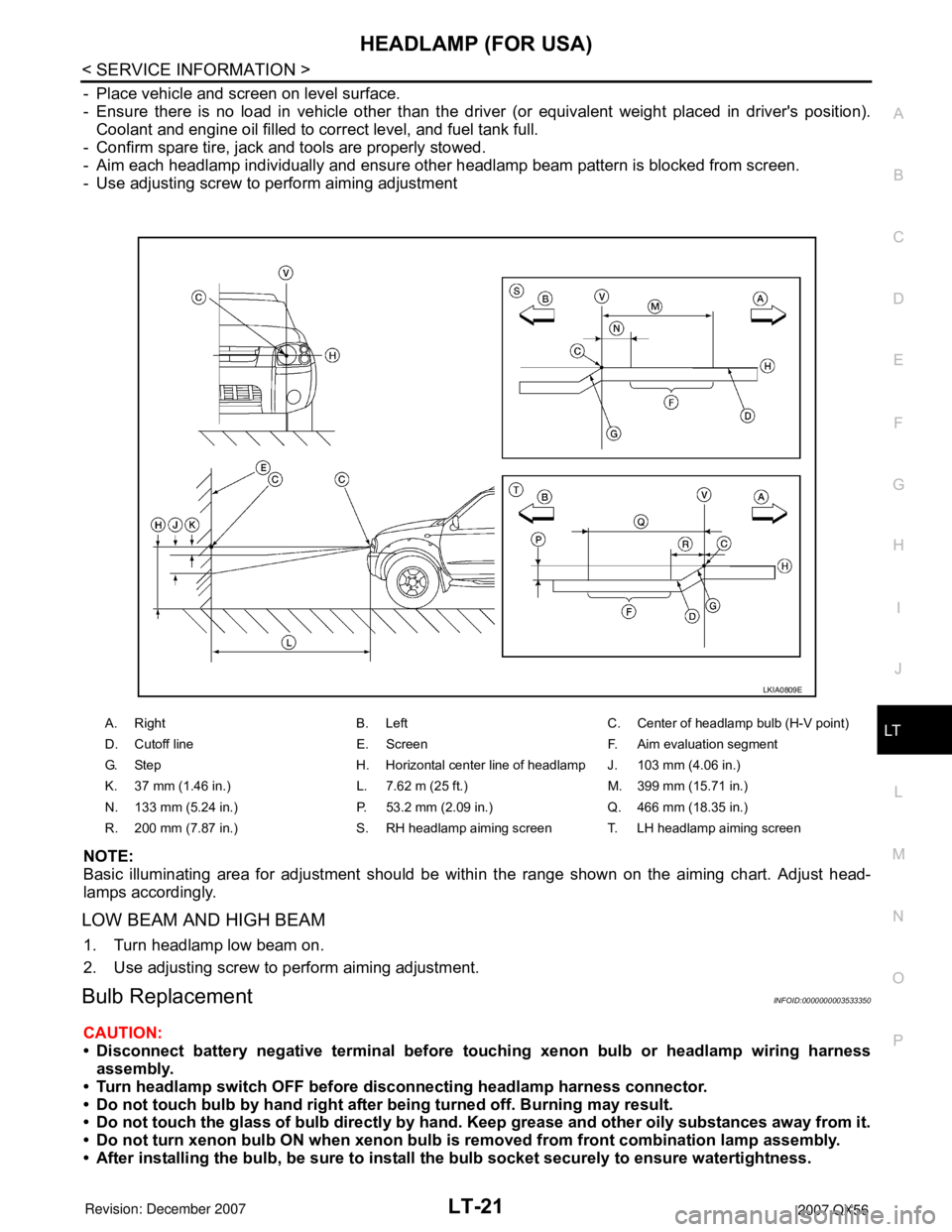
- Place vehicle and screen on level surface.
- Ensure there is no load in vehicle other than the driver (or equivalent weight placed in driver's position).
Coolant and engine oil filled to correct level, and fuel tank full.
- Confirm spare tire, jack and tools are properly stowed.
- Aim each headlamp individually and ensure other headlamp beam pattern is blocked from screen.
- Use adjusting screw to perform aiming adjustment
NOTE:
Basic illuminating area for adjustment should be within the range shown on the aiming chart. Adjust head-
lamps accordingly.
LOW BEAM AND HIGH BEAM
1. Turn headlamp low beam on.
2. Use adjusting screw to perform aiming adjustment.
Bulb ReplacementINFOID:0000000003533350
CAUTION:
• Disconnect battery negative terminal before touching xenon bulb or headlamp wiring harness
assembly.
• Turn headlamp switch OFF before disconnecting headlamp harness connector.
• Do not touch bulb by hand right after being turned off. Burning may result.
• Do not touch the glass of bulb directly by hand. Keep grease and other oily substances away from it.
• Do not turn xenon bulb ON when xenon bulb is removed from front combination lamp assembly.
• After installing the bulb, be sure to install the bulb socket securely to ensure watertightness.
A. Right B. Left C. Center of headlamp bulb (H-V point)
D. Cutoff line E. Screen F. Aim evaluation segment
G. Step H. Horizontal center line of headlamp J. 103 mm (4.06 in.)
K. 37 mm (1.46 in.) L. 7.62 m (25 ft.) M. 399 mm (15.71 in.)
N. 133 mm (5.24 in.) P. 53.2 mm (2.09 in.) Q. 466 mm (18.35 in.)
R. 200 mm (7.87 in.) S. RH headlamp aiming screen T. LH headlamp aiming screen
LKIA0809E
Page 2262 of 3061

FRONT FOG LAMP
LT-55
< SERVICE INFORMATION >
C
D
E
F
G
H
I
J
L
MA
B
LT
N
O
P
Aiming AdjustmentINFOID:0000000003533400
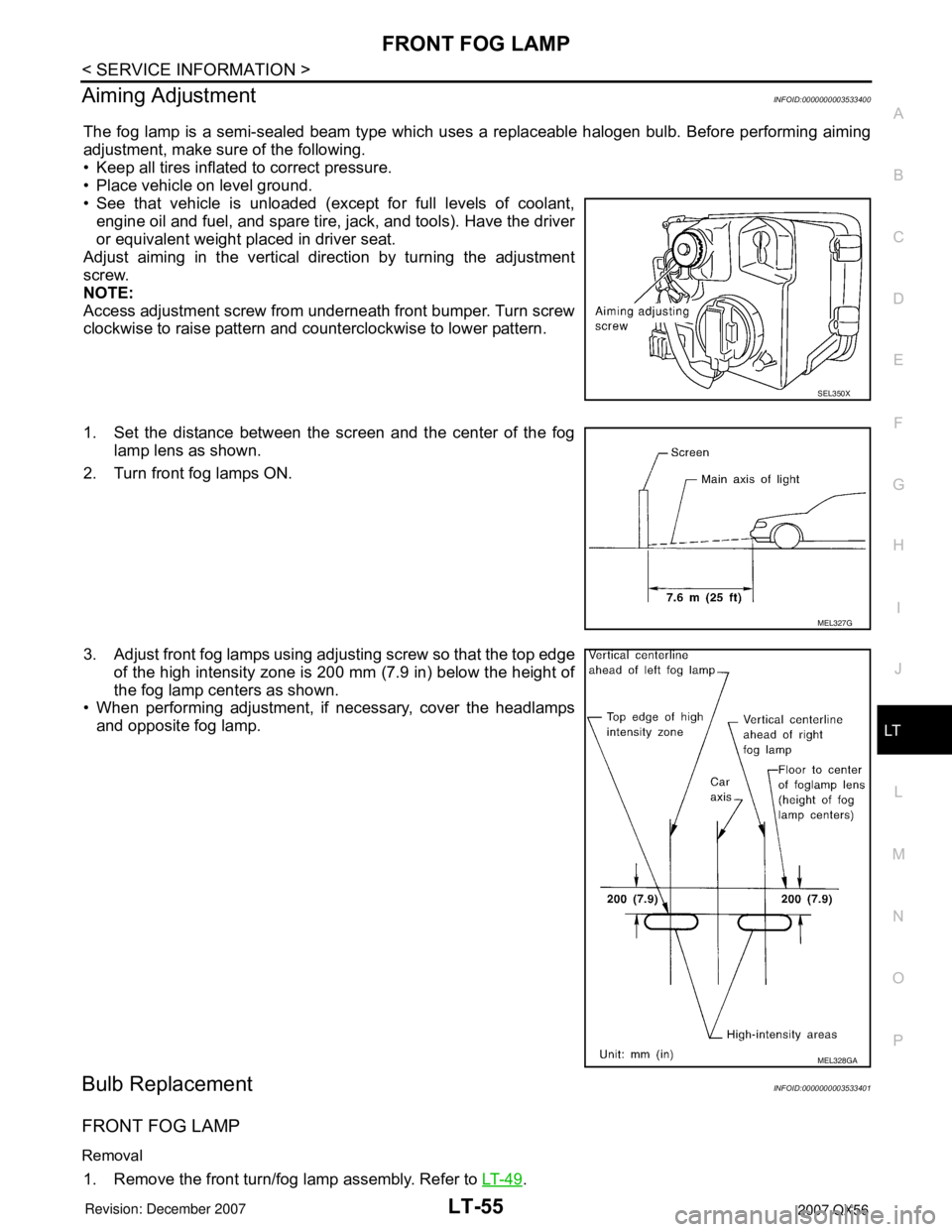
The fog lamp is a semi-sealed beam type which uses a replaceable halogen bulb. Before performing aiming
adjustment, make sure of the following.
• Keep all tires inflated to correct pressure.
• Place vehicle on level ground.
• See that vehicle is unloaded (except for full levels of coolant,
engine oil and fuel, and spare tire, jack, and tools). Have the driver
or equivalent weight placed in driver seat.
Adjust aiming in the vertical direction by turning the adjustment
screw.
NOTE:
Access adjustment screw from underneath front bumper. Turn screw
clockwise to raise pattern and counterclockwise to lower pattern.
1. Set the distance between the screen and the center of the fog
lamp lens as shown.
2. Turn front fog lamps ON.
3. Adjust front fog lamps using adjusting screw so that the top edge
of the high intensity zone is 200 mm (7.9 in) below the height of
the fog lamp centers as shown.
• When performing adjustment, if necessary, cover the headlamps
and opposite fog lamp.
Bulb ReplacementINFOID:0000000003533401
FRONT FOG LAMP
Removal
1. Remove the front turn/fog lamp assembly. Refer to LT- 4 9.
SEL350X
MEL327G
MEL328GA
Page 2363 of 3061

MA-1
MAINTENANCE
C
D
E
F
G
H
I
J
K
M
SECTION MA
A
B
MA
N
O
P
CONTENTS
MAINTENANCE
SERVICE INFORMATION ............................2
PRECAUTIONS ...................................................2
Precaution for Supplemental Restraint System
(SRS) "AIR BAG" and "SEAT BELT PRE-TEN-
SIONER" ...................................................................
2
PREPARATION ...................................................3
Special Service Tool .................................................3
Commercial Service Tool ..........................................3
GENERAL MAINTENANCE ................................4
General Maintenance ................................................4
PERIODIC MAINTENANCE ................................6
Introduction of Periodic Maintenance ........................6
Maintenance for Off-road Driving (4WD only) ...........6
Schedule 1 ................................................................6
Schedule 2 ................................................................8
RECOMMENDED FLUIDS AND LUBRI-
CANTS ................................................................
10
Fluids and Lubricants ..............................................10
SAE Viscosity Number ............................................10
ENGINE MAINTENANCE ...................................12
Checking Drive Belts ...............................................12
Changing Engine Coolant .......................................12
Checking Fuel Line .................................................15
Changing Fuel Filter ................................................15
Changing Engine Air Cleaner Filter .........................15
Changing Engine Oil ................................................16
Changing Oil Filter ...................................................16
Changing Spark Plugs .............................................18
Checking EVAP Vapor Line .....................................19
CHASSIS AND BODY MAINTENANCE ...........20
Changing In-cabin Microfilter ...................................20
Checking Exhaust System .......................................21
Checking Automatic Transmission Fluid (ATF) .......21
Changing Automatic Transmission Fluid (ATF) .......23
Changing Transfer Fluid ..........................................23
Checking Transfer Fluid ..........................................24
Checking Propeller Shaft .........................................24
Checking Final Drive Oil ..........................................24
Changing Final Drive Oil ..........................................25
Balancing Wheels ....................................................25
Tire Rotation ............................................................27
Checking Brake Fluid Level and Leaks ...................27
CheckingBrake Line and Cables .............................27
Checking Disc Brake ...............................................27
Checking Steering Gear and Linkage ......................28
Checking Power Steering Fluid and Line ................28
Checking Axle and Suspension Parts .....................29
Lubricating Locks, Hinges and Hood Latches .........30
Checking Seat Belts, Buckles, Retractors, An-
chors and Adjusters .................................................
30