2007 INFINITI QX56 reset
[x] Cancel search: resetPage 2081 of 3061
GW-62
< SERVICE INFORMATION >
REAR DOOR GLASS AND REGULATOR
REAR DOOR GLASS AND REGULATOR
Removal and InstallationINFOID:0000000003533062
REAR DOOR GLASS
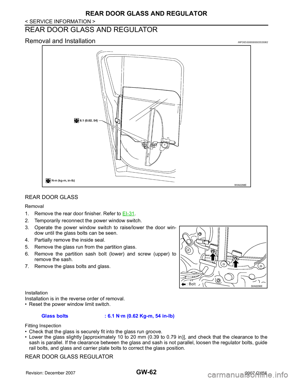
Removal
1. Remove the rear door finisher. Refer to EI-31.
2. Temporarily reconnect the power window switch.
3. Operate the power window switch to raise/lower the door win-
dow until the glass bolts can be seen.
4. Partially remove the inside seal.
5. Remove the glass run from the partition glass.
6. Remove the partition sash bolt (lower) and screw (upper) to
remove the sash.
7. Remove the glass bolts and glass.
Installation
Installation is in the reverse order of removal.
• Reset the power window limit switch.
Fitting Inspection
• Check that the glass is securely fit into the glass run groove.
• Lower the glass slightly [approximately 10 to 20 mm (0.39 to 0.79 in)], and check that the clearance to the
sash is parallel. If the clearance between the glass and sash is not parallel, loosen the regulator bolts, guide
rail bolts, and glass and carrier plate bolts to correct the glass position.
REAR DOOR GLASS REGULATOR
WIIA0298E
SIIA0290E
Glass bolts : 6.1 N·m (0.62 Kg-m, 54 in-lb)
Page 2082 of 3061
REAR DOOR GLASS AND REGULATOR
GW-63
< SERVICE INFORMATION >
C
D
E
F
G
H
J
K
L
MA
B
GW
N
O
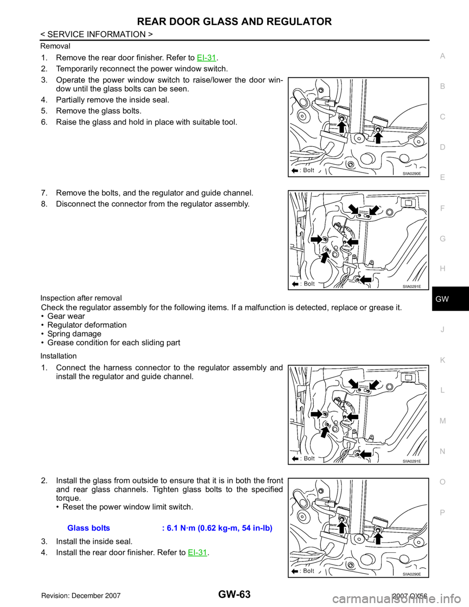
P Removal
1. Remove the rear door finisher. Refer to EI-31.
2. Temporarily reconnect the power window switch.
3. Operate the power window switch to raise/lower the door win-
dow until the glass bolts can be seen.
4. Partially remove the inside seal.
5. Remove the glass bolts.
6. Raise the glass and hold in place with suitable tool.
7. Remove the bolts, and the regulator and guide channel.
8. Disconnect the connector from the regulator assembly.
Inspection after removal
Check the regulator assembly for the following items. If a malfunction is detected, replace or grease it.
• Gear wear
• Regulator deformation
• Spring damage
• Grease condition for each sliding part
Installation
1. Connect the harness connector to the regulator assembly and
install the regulator and guide channel.
2. Install the glass from outside to ensure that it is in both the front
and rear glass channels. Tighten glass bolts to the specified
torque.
• Reset the power window limit switch.
3. Install the inside seal.
4. Install the rear door finisher. Refer to EI-31
.
SIIA0290E
SIIA0291E
SIIA0291E
Glass bolts : 6.1 N·m (0.62 kg-m, 54 in-lb)
SIIA0290E
Page 2083 of 3061
GW-64
< SERVICE INFORMATION >
REAR DOOR GLASS AND REGULATOR
SETTING AFTER INSTALLATION
Setting of Limit Switch
If any of the following work has been done, set the limit switch (integrated in the motor).
• Removal and installation of the regulator.
• Removal and installation of the motor from the regulator.
• Removal and installation of the glass.
• Removal and installation of the glass run.
Resetting
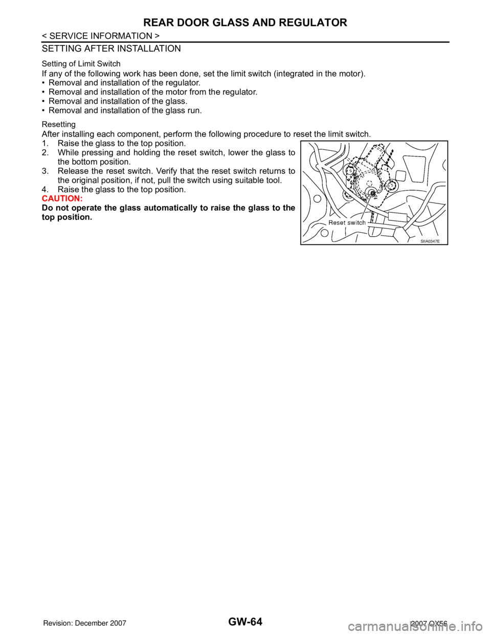
After installing each component, perform the following procedure to reset the limit switch.
1. Raise the glass to the top position.
2. While pressing and holding the reset switch, lower the glass to
the bottom position.
3. Release the reset switch. Verify that the reset switch returns to
the original position, if not, pull the switch using suitable tool.
4. Raise the glass to the top position.
CAUTION:
Do not operate the glass automatically to raise the glass to the
top position.
SIIA0347E
Page 2543 of 3061
SUNROOF
RF-11
< SERVICE INFORMATION >
C
D
E
F
G
H
J
K
L
MA
B
RF
N
O
P
• through sunroof switch terminal 4
• through sunroof switch terminal 2
• through sunroof motor assembly terminal 8
• through grounds M57, M61 and M79.
Then, the sunroof will tilt up.
TILT DOWN OPERATION
When the tilt switch is operated for tilt down, ground is supplied
• to sunroof motor assembly terminal 10
• through sunroof switch terminal 6
• through sunroof switch terminal 2
• through sunroof motor assembly terminal 8
• through grounds M57, M61 and M79.
Then, the sunroof will tilt down.
SLIDE OPEN OPERATION
When the switch is operated for slide open, ground is supplied
• to sunroof motor assembly terminal 9
• through sunroof switch terminal 3
• through sunroof switch terminal 2
• through sunroof motor assembly terminal 8
• through grounds M57, M61 and M79.
Then, the sunroof will slide open.
SLIDE CLOSE OPERATION
When the switch is operated for slide close, ground is supplied
• to sunroof motor assembly terminal 3
• through sunroof switch terminal 1
• through sunroof switch terminal 2
• through sunroof motor assembly terminal 8
• through grounds M57, M61 and M79.
Then, the sunroof will slide closed.
RETAINED POWER OPERATION
When the ignition switch is turned to OFF position from ON or START position, power is supplied for 45 sec-
onds.
The retained power operation is canceled when the driver or passenger side door is opened.
RAP signal period can be changed by CONSULT-II. Refer to RF-14, "
CONSULT-II Function (BCM)".
MEMORY RESET PROCEDURE
To reset the sunroof motor memory from any sunroof position (full open, partially open, closed, partially
vented, and vented), push and hold the sunroof tilt switch in the forward (DOWN) position until the sunroof is
fully closed. After it has closed all the way, push and hold the tilt switch forward (DOWN) for more than 2 sec-
onds to re-establish the motor preset position. The sunroof should now operate normally.
INTERRUPTION DETECTION FUNCTION
The CPU (central processing unit) monitors the sunroof motor operation and the sunroof position (fully-closed
or other) by the signals from the sunroof motor.
When sunroof motor detects an interruption during the following sliding close operations, sunroof switch con-
trols the motor for open and the sunroof will operate until it reaches full open position.
• automatic close operation when ignition switch is in the ON position.
• automatic close operation during retained power operation.
CAN Communication System DescriptionINFOID:0000000003533097
Refer to LAN-4.
Page 2556 of 3061
RF-24
< SERVICE INFORMATION >
SUNROOF
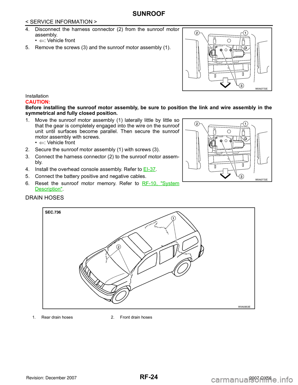
4. Disconnect the harness connector (2) from the sunroof motor
assembly.
•⇐: Vehicle front
5. Remove the screws (3) and the sunroof motor assembly (1).
Installation
CAUTION:
Before installing the sunroof motor assembly, be sure to position the link and wire assembly in the
symmetrical and fully closed position.
1. Move the sunroof motor assembly (1) laterally little by little so
that the gear is completely engaged into the wire on the sunroof
unit until surfaces become parallel. Then secure the sunroof
motor assembly with screws.
•⇐: Vehicle front
2. Secure the sunroof motor assembly (1) with screws (3).
3. Connect the harness connector (2) to the sunroof motor assem-
bly.
4. Install the overhead console assembly. Refer to EI-37
.
5. Connect the battery positive and negative cables.
6. Reset the sunroof motor memory. Refer to RF-10, "
System
Description".
DRAIN HOSES
WIIA0772E
WIIA0772E
1. Rear drain hoses 2. Front drain hoses
WIIA0853E
Page 2602 of 3061
RSU-12
< SERVICE INFORMATION >
TROUBLE DIAGNOSIS
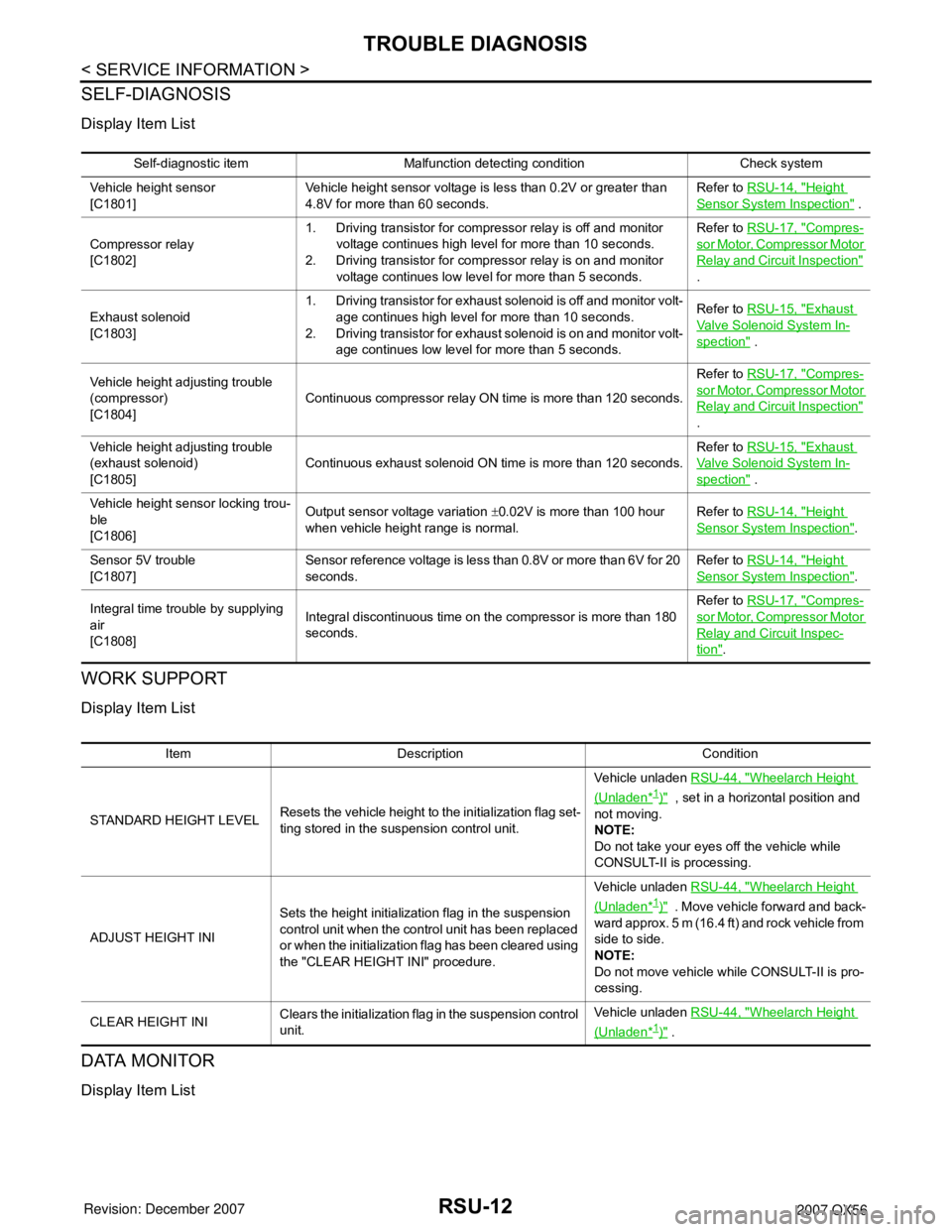
SELF-DIAGNOSIS
Display Item List
WORK SUPPORT
Display Item List
DATA MONITOR
Display Item List
Self-diagnostic item Malfunction detecting condition Check system
Vehicle height sensor
[C1801]Vehicle height sensor voltage is less than 0.2V or greater than
4.8V for more than 60 seconds.Refer to RSU-14, "
Height
Sensor System Inspection" .
Compressor relay
[C1802]1. Driving transistor for compressor relay is off and monitor
voltage continues high level for more than 10 seconds.
2. Driving transistor for compressor relay is on and monitor
voltage continues low level for more than 5 seconds.Refer to RSU-17, "
Compres-
sor Motor, Compressor Motor
Relay and Circuit Inspection"
.
Exhaust solenoid
[C1803]1. Driving transistor for exhaust solenoid is off and monitor volt-
age continues high level for more than 10 seconds.
2. Driving transistor for exhaust solenoid is on and monitor volt-
age continues low level for more than 5 seconds.Refer to RSU-15, "
Exhaust
Valve Solenoid System In-
spection" .
Vehicle height adjusting trouble
(compressor)
[C1804]Continuous compressor relay ON time is more than 120 seconds.Refer to RSU-17, "
Compres-
sor Motor, Compressor Motor
Relay and Circuit Inspection"
.
Vehicle height adjusting trouble
(exhaust solenoid)
[C1805]Continuous exhaust solenoid ON time is more than 120 seconds.Refer to RSU-15, "
Exhaust
Valve Solenoid System In-
spection" .
Vehicle height sensor locking trou-
ble
[C1806]Output sensor voltage variation ±0.02V is more than 100 hour
when vehicle height range is normal.Refer to RSU-14, "
Height
Sensor System Inspection".
Sensor 5V trouble
[C1807]Sensor reference voltage is less than 0.8V or more than 6V for 20
seconds.Refer to RSU-14, "
Height
Sensor System Inspection".
Integral time trouble by supplying
air
[C1808]Integral discontinuous time on the compressor is more than 180
seconds.Refer to RSU-17, "
Compres-
sor Motor, Compressor Motor
Relay and Circuit Inspec-
tion".
Item Description Condition
STANDARD HEIGHT LEVELResets the vehicle height to the initialization flag set-
ting stored in the suspension control unit.Vehicle unladen RSU-44, "
Wheelarch Height
(Unladen*1)" , set in a horizontal position and
not moving.
NOTE:
Do not take your eyes off the vehicle while
CONSULT-II is processing.
ADJUST HEIGHT INISets the height initialization flag in the suspension
control unit when the control unit has been replaced
or when the initialization flag has been cleared using
the "CLEAR HEIGHT INI" procedure.Vehicle unladen RSU-44, "
Wheelarch Height
(Unladen*1)" . Move vehicle forward and back-
ward approx. 5 m (16.4 ft) and rock vehicle from
side to side.
NOTE:
Do not move vehicle while CONSULT-II is pro-
cessing.
CLEAR HEIGHT INIClears the initialization flag in the suspension control
unit.Vehicle unladen RSU-44, "
Wheelarch Height
(Unladen*1)" .
Page 2702 of 3061
SE-30
< SERVICE INFORMATION >
AUTOMATIC DRIVE POSITIONER
Work Flow
INFOID:0000000003533166
1. Check the symptom and customer's requests.
2. Understand the system description. Refer to SE-11, "
System Description".
3. Perform the preliminary check. Refer to SE-30, "
Preliminary Check" .
4. Check the self-diagnosis, results using CONSULT-II. Refer to SE-32, "
CONSULT-II Function (AUTO
DRIVE POS.)".
5. Repair or replace depending on the self-diagnostic results.
6. Based on the trouble diagnosis chart, repair or replace the cause of the malfunction. Refer to SE-35,
"Symptom Chart" .
7. Does the automatic drive positioner system operate normally?
If it is normal, GO TO 8.
If it is not normal, GO TO 3.
8. Inspection End.
Preliminary CheckINFOID:0000000003533167
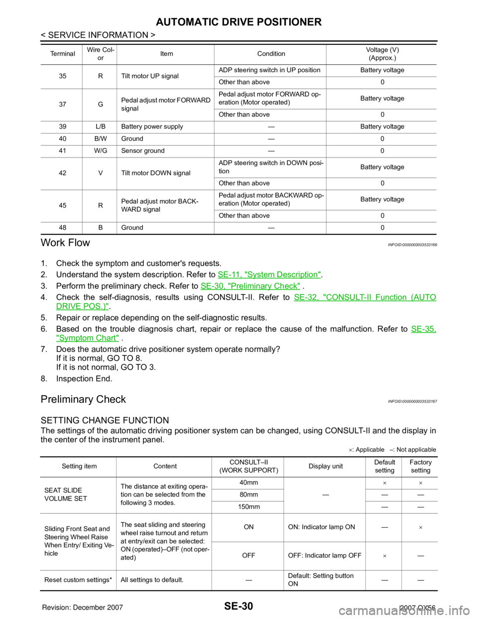
SETTING CHANGE FUNCTION
The settings of the automatic driving positioner system can be changed, using CONSULT-II and the display in
the center of the instrument panel.
×: Applicable –: Not applicable
35 R Tilt motor UP signalADP steering switch in UP position Battery voltage
Other than above 0
37 GPedal adjust motor FORWARD
signalPedal adjust motor FORWARD op-
eration (Motor operated)Battery voltage
Other than above 0
39 L/B Battery power supply — Battery voltage
40 B/W Ground — 0
41 W/G Sensor ground — 0
42 V Tilt motor DOWN signalADP steering switch in DOWN posi-
tionBattery voltage
Other than above 0
45 RPedal adjust motor BACK-
WARD signalPedal adjust motor BACKWARD op-
eration (Motor operated)Battery voltage
Other than above 0
48 B Ground — 0 Te r m i n a l Wire Col-
orItem ConditionVoltage (V)
(Approx.)
Setting item ContentCONSULT–II
(WORK SUPPORT)Display unitDefault
settingFactory
setting
SEAT SLIDE
VOLUME SETThe distance at exiting opera-
tion can be selected from the
following 3 modes.40mm
—××
80mm — —
150mm — —
Sliding Front Seat and
Steering Wheel Raise
When Entry/ Exiting Ve-
hicleThe seat sliding and steering
wheel raise turnout and return
at entry/exit can be selected:
ON (operated)–OFF (not oper-
ated)ON ON: Indicator lamp ON —×
OFF OFF: Indicator lamp OFF×—
Reset custom settings* All settings to default. —Default: Setting button
ON——
Page 2703 of 3061
AUTOMATIC DRIVE POSITIONER
SE-31
< SERVICE INFORMATION >
C
D
E
F
G
H
J
K
L
MA
B
SE
N
O
P
It is possible to set sliding front seat for entry/exit of vehicle by pressing set switch.
*: Setting of sliding front seat for entry/exit of vehicle is ON at factory-shipment. But if custom settings are reset, setting turns OFF.
NOTE:
After the setting is registered, the new setting is effective, even if the battery is disconnected.
BCM Power Supply and Ground Circuit InspectionINFOID:0000000003533168
Refer to BCS-15, "BCM Power Supply and Ground Circuit Inspection".
Power Supply and Ground Circuit InspectionINFOID:0000000003533169
1.CHECK DRIVER SEAT CONTROL UNIT FUSES AND FUSIBLE LINK
Make sure any of the following fuses in the driver seat control unit and automatic drive positioner control unit
are not blown.
OK or NG
OK >> GO TO 2.
NG >> If fuse is blown, be sure to eliminate cause of malfunction before installing new fuse.
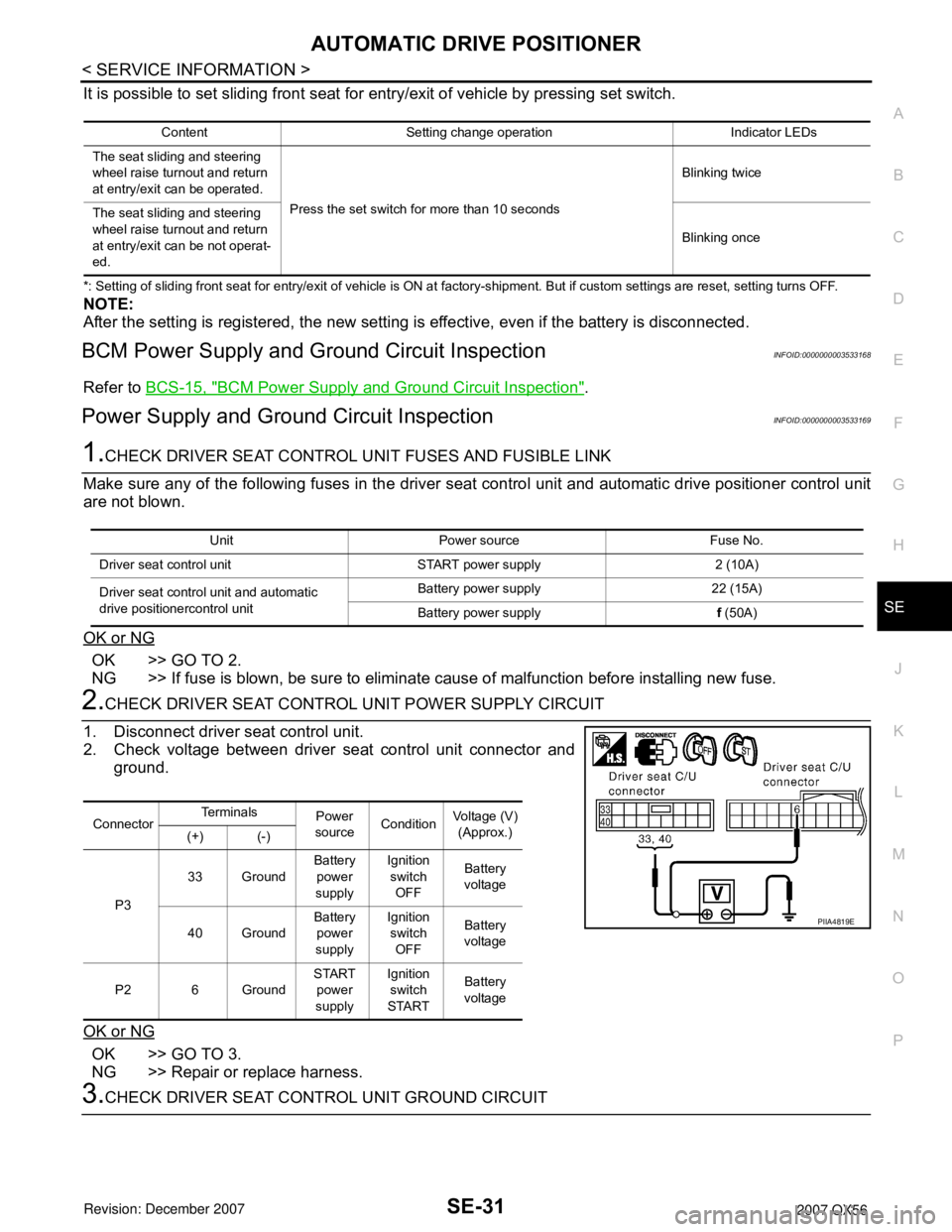
2.CHECK DRIVER SEAT CONTROL UNIT POWER SUPPLY CIRCUIT
1. Disconnect driver seat control unit.
2. Check voltage between driver seat control unit connector and
ground.
OK or NG
OK >> GO TO 3.
NG >> Repair or replace harness.
3.CHECK DRIVER SEAT CONTROL UNIT GROUND CIRCUIT
Content Setting change operation Indicator LEDs
The seat sliding and steering
wheel raise turnout and return
at entry/exit can be operated.
Press the set switch for more than 10 secondsBlinking twice
The seat sliding and steering
wheel raise turnout and return
at entry/exit can be not operat-
ed.Blinking once
Unit Power source Fuse No.
Driver seat control unit START power supply 2 (10A)
Driver seat control unit and automatic
drive positionercontrol unitBattery power supply 22 (15A)
Battery power supplyf (50A)
ConnectorTe r m i n a l s
Power
sourceConditionVoltage (V)
(Approx.)
(+) (-)
P333 GroundBattery
power
supplyIgnition
switch
OFFBattery
voltage
40 GroundBattery
power
supplyIgnition
switch
OFFBattery
voltage
P2 6 GroundSTART
power
supplyIgnition
switch
STARTBattery
voltage
PIIA4819E