2007 INFINITI QX56 recommended oil
[x] Cancel search: recommended oilPage 1825 of 3061
CAMSHAFTEM-55
< SERVICE INFORMATION >
C
DE
F
G H
I
J
K L
M A
EM
NP
O
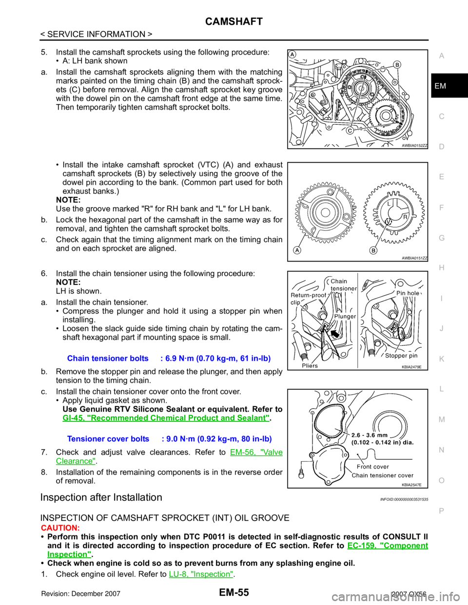
5. Install the camshaft sprockets using the following procedure:
• A: LH bank shown
a. Install the camshaft sprockets aligning them with the matching marks painted on the timing chain (B) and the camshaft sprock-
ets (C) before removal. Align the camshaft sprocket key groove
with the dowel pin on the camshaft front edge at the same time.
Then temporarily tighten camshaft sprocket bolts.
• Install the intake camshaft sprocket (VTC) (A) and exhaust
camshaft sprockets (B) by select ively using the groove of the
dowel pin according to the bank. (Common part used for both
exhaust banks.)
NOTE:
Use the groove marked "R" for RH bank and "L" for LH bank.
b. Lock the hexagonal part of the camshaft in the same way as for removal, and tighten the camshaft sprocket bolts.
c. Check again that the timing alignment mark on the timing chain and on each sprocket are aligned.
6. Install the chain tensioner using the following procedure: NOTE:
LH is shown.
a. Install the chain tensioner. • Compress the plunger and hold it using a stopper pin wheninstalling.
• Loosen the slack guide side timing chain by rotating the cam- shaft hexagonal part if mounting space is small.
b. Remove the stopper pin and release the plunger, and then apply tension to the timing chain.
c. Install the chain tensioner cover onto the front cover. • Apply liquid gasket as shown.
Use Genuine RTV Silicone Seal ant or equivalent. Refer to
GI-45, "
Recommended Chemical Product and Sealant".
7. Check and adjust valve clearances. Refer to EM-56, "
Va l v e
Clearance".
8. Installation of the remaining components is in the reverse order of removal.
Inspection after InstallationINFOID:0000000003531535
INSPECTION OF CAMSHAFT SPROCKET (INT) OIL GROOVE
CAUTION:
• Perform this inspection only when DTC P0011 is de tected in self-diagnostic results of CONSULT II
and it is directed according to inspect ion procedure of EC section. Refer to EC-159, "
Component
Inspection".
• Check when engine is cold so as to pr event burns from any splashing engine oil.
1. Check engine oil level. Refer to LU-8, "
Inspection".
AWBIA0152ZZ
AWBIA0151ZZ
Chain tensioner bolts : 6.9 N·m (0.70 kg-m, 61 in-lb)
Tensioner cover bolts : 9.0 N·m (0.92 kg-m, 80 in-lb)KBIA2479E
KBIA2547E
Page 1839 of 3061
CYLINDER HEAD
EM-69
< SERVICE INFORMATION >
C
D
E
F
G
H
I
J
K
L
MA
EM
N
P O
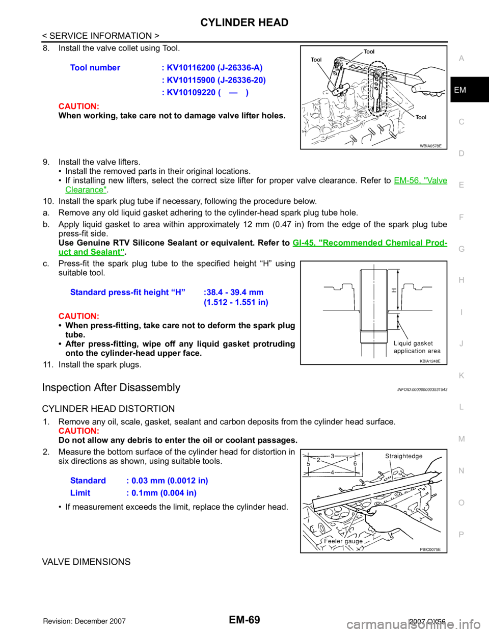
8. Install the valve collet using Tool.
CAUTION:
When working, take care not to damage valve lifter holes.
9. Install the valve lifters.
• Install the removed parts in their original locations.
• If installing new lifters, select the correct size lifter for proper valve clearance. Refer to EM-56, "
Va l v e
Clearance".
10. Install the spark plug tube if necessary, following the procedure below.
a. Remove any old liquid gasket adhering to the cylinder-head spark plug tube hole.
b. Apply liquid gasket to area within approximately 12 mm (0.47 in) from the edge of the spark plug tube
press-fit side.
Use Genuine RTV Silicone Sealant or equivalent. Refer to GI-45, "
Recommended Chemical Prod-
uct and Sealant".
c. Press-fit the spark plug tube to the specified height “H” using
suitable tool.
CAUTION:
• When press-fitting, take care not to deform the spark plug
tube.
• After press-fitting, wipe off any liquid gasket protruding
onto the cylinder-head upper face.
11. Install the spark plugs.
Inspection After DisassemblyINFOID:0000000003531543
CYLINDER HEAD DISTORTION
1. Remove any oil, scale, gasket, sealant and carbon deposits from the cylinder head surface.
CAUTION:
Do not allow any debris to enter the oil or coolant passages.
2. Measure the bottom surface of the cylinder head for distortion in
six directions as shown, using suitable tools.
• If measurement exceeds the limit, replace the cylinder head.
VALVE DIMENSIONS
Tool number : KV10116200 (J-26336-A)
: KV10115900 (J-26336-20)
: KV10109220 ( — )
WBIA0578E
Standard press-fit height “H” :38.4 - 39.4 mm
(1.512 - 1.551 in)
KBIA1248E
Standard : 0.03 mm (0.0012 in)
Limit : 0.1mm (0.004 in)
PBIC0075E
Page 1852 of 3061
EM-82
< SERVICE INFORMATION >
CYLINDER BLOCK
ASSEMBLY
1. Fully air-blow the coolant and oil passages in the cylinder block, cylinder bore, and crankcase to remove
any foreign material.
CAUTION:
Use goggles to protect your eyes.
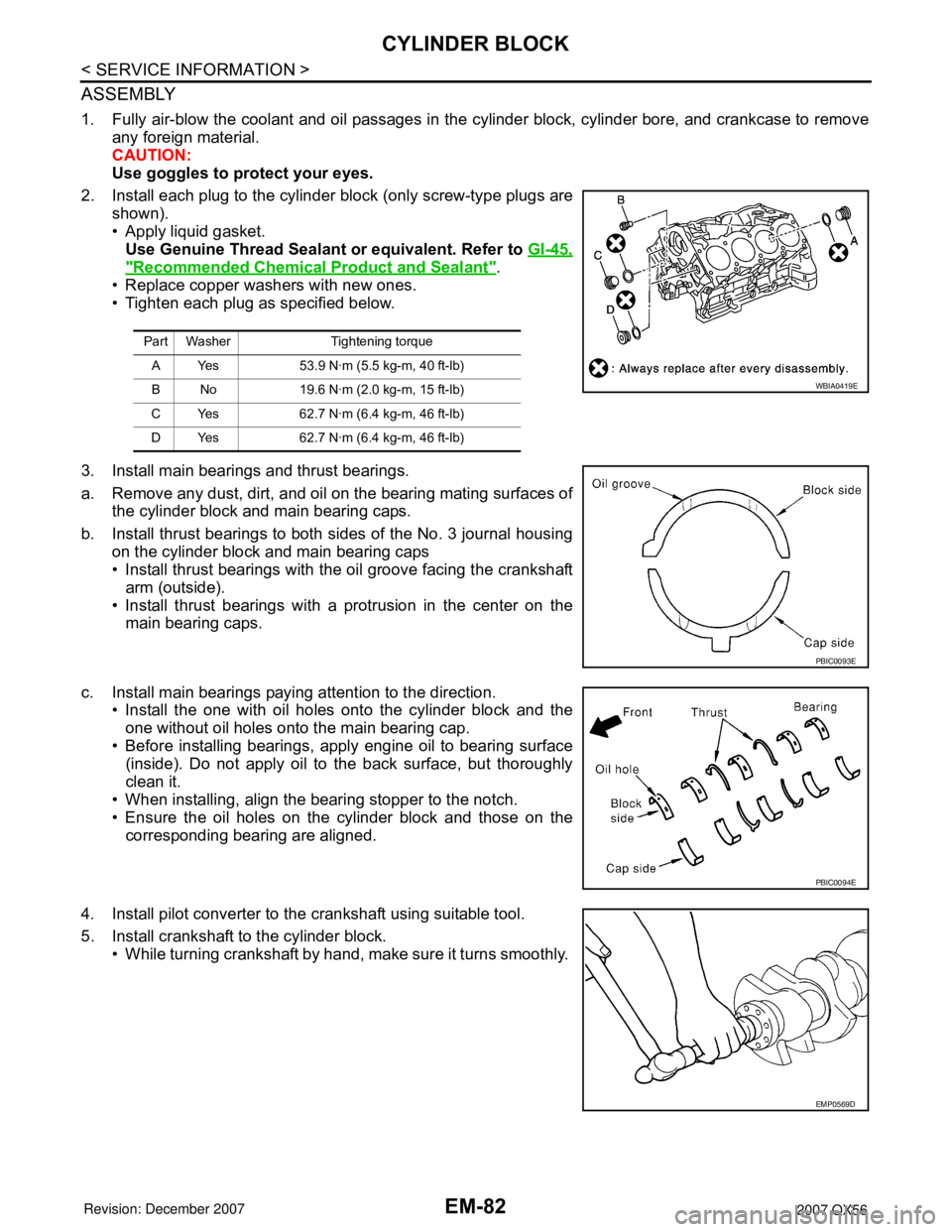
2. Install each plug to the cylinder block (only screw-type plugs are
shown).
• Apply liquid gasket.
Use Genuine Thread Sealant or equivalent. Refer to GI-45,
"Recommended Chemical Product and Sealant".
• Replace copper washers with new ones.
• Tighten each plug as specified below.
3. Install main bearings and thrust bearings.
a. Remove any dust, dirt, and oil on the bearing mating surfaces of
the cylinder block and main bearing caps.
b. Install thrust bearings to both sides of the No. 3 journal housing
on the cylinder block and main bearing caps
• Install thrust bearings with the oil groove facing the crankshaft
arm (outside).
• Install thrust bearings with a protrusion in the center on the
main bearing caps.
c. Install main bearings paying attention to the direction.
• Install the one with oil holes onto the cylinder block and the
one without oil holes onto the main bearing cap.
• Before installing bearings, apply engine oil to bearing surface
(inside). Do not apply oil to the back surface, but thoroughly
clean it.
• When installing, align the bearing stopper to the notch.
• Ensure the oil holes on the cylinder block and those on the
corresponding bearing are aligned.
4. Install pilot converter to the crankshaft using suitable tool.
5. Install crankshaft to the cylinder block.
• While turning crankshaft by hand, make sure it turns smoothly.
Part Washer Tightening torque
A Yes 53.9 N·m (5.5 kg-m, 40 ft-lb)
B No 19.6 N·m (2.0 kg-m, 15 ft-lb)
C Yes 62.7 N·m (6.4 kg-m, 46 ft-lb)
D Yes 62.7 N·m (6.4 kg-m, 46 ft-lb)
WBIA0419E
PBIC0093E
PBIC0094E
EMP0569D
Page 1854 of 3061
EM-84
< SERVICE INFORMATION >
CYLINDER BLOCK
• Tap until flattened with the front edge of the rear oil seal
retainer using suitable tool.
• Fit the rear oil seal until it is level with the rear end surface of
rear oil seal retainer.
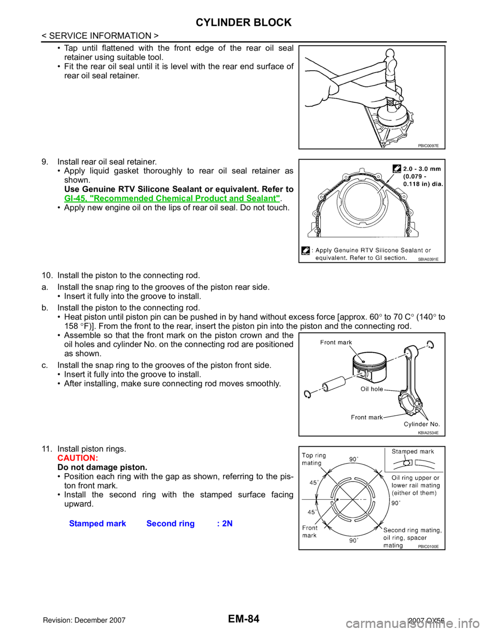
9. Install rear oil seal retainer.
• Apply liquid gasket thoroughly to rear oil seal retainer as
shown.
Use Genuine RTV Silicone Sealant or equivalent. Refer to
GI-45, "
Recommended Chemical Product and Sealant".
• Apply new engine oil on the lips of rear oil seal. Do not touch.
10. Install the piston to the connecting rod.
a. Install the snap ring to the grooves of the piston rear side.
• Insert it fully into the groove to install.
b. Install the piston to the connecting rod.
• Heat piston until piston pin can be pushed in by hand without excess force [approx. 60° to 70 C° (140° to
158 °F)]. From the front to the rear, insert the piston pin into the piston and the connecting rod.
• Assemble so that the front mark on the piston crown and the
oil holes and cylinder No. on the connecting rod are positioned
as shown.
c. Install the snap ring to the grooves of the piston front side.
• Insert it fully into the groove to install.
• After installing, make sure connecting rod moves smoothly.
11. Install piston rings.
CAUTION:
Do not damage piston.
• Position each ring with the gap as shown, referring to the pis-
ton front mark.
• Install the second ring with the stamped surface facing
upward.
PBIC0097E
SBIA0391E
KBIA2534E
Stamped mark Second ring : 2N
PBIC0100E
Page 1901 of 3061
FFD-2
< SERVICE INFORMATION >
PRECAUTIONS
SERVICE INFORMATION
PRECAUTIONS
Precaution for Servicing Front Final DriveINFOID:0000000003532584
• Before starting diagnosis of the vehicle, understand the symptoms well. Perform correct and systematic
operations.
• Check for the correct installation status prior to removal or disassembly. When matching marks are required,
be certain they do not interfere with the function of the parts they are applied to.
• Overhaul should be done in a clean work area, a dust proof area is recommended.
• Before disassembly, completely remove sand and mud from the exterior of the unit, preventing them from
entering into the unit during disassembly or assembly.
• Always use shop paper for cleaning the inside of components.
• Avoid using cotton gloves or a shop cloth to prevent the entering of lint.
• Check appearance of the disassembled parts for damage, deformation, and abnormal wear. Replace them
with new ones if necessary.
• Gaskets, seals and O-rings should be replaced any time the unit is disassembled.
• Clean and flush the parts sufficiently and blow them dry.
• Be careful not to damage sliding surfaces and mating surfaces.
• When applying sealant, remove the old sealant from the mating surface; then remove any moisture, oil, and
foreign materials from the application and mating surfaces.
• In principle, tighten nuts or bolts gradually in several steps working diagonally from inside to outside. If a
tightening sequence is specified, observe it.
• During assembly, observe the specified tightening torque.
• Add new differential gear oil, petroleum jelly, or multi-purpose grease, as specified.
Page 1906 of 3061
DIFFERENTIAL GEAR OIL
FFD-7
< SERVICE INFORMATION >
C
E
F
G
H
I
J
K
L
MA
B
FFD
N
O
P
DIFFERENTIAL GEAR OIL
Changing Differential Gear OilINFOID:0000000003532588
DRAINING
1. Stop the engine.
2. Remove the drain plug from the front final drive assembly to drain the differential gear oil.
3. Install the drain plug with sealant applied on the threads to the front final drive assembly. Tighten to the
specified torque. Refer to FFD-13, "
Disassembly and Assembly".
• Use High Performance Thread Sealant or equivalent. Refer to GI-45, "
Recommended Chemical Product
and Sealant".
FILLING
1. Remove the filler plug from the front final drive assembly.
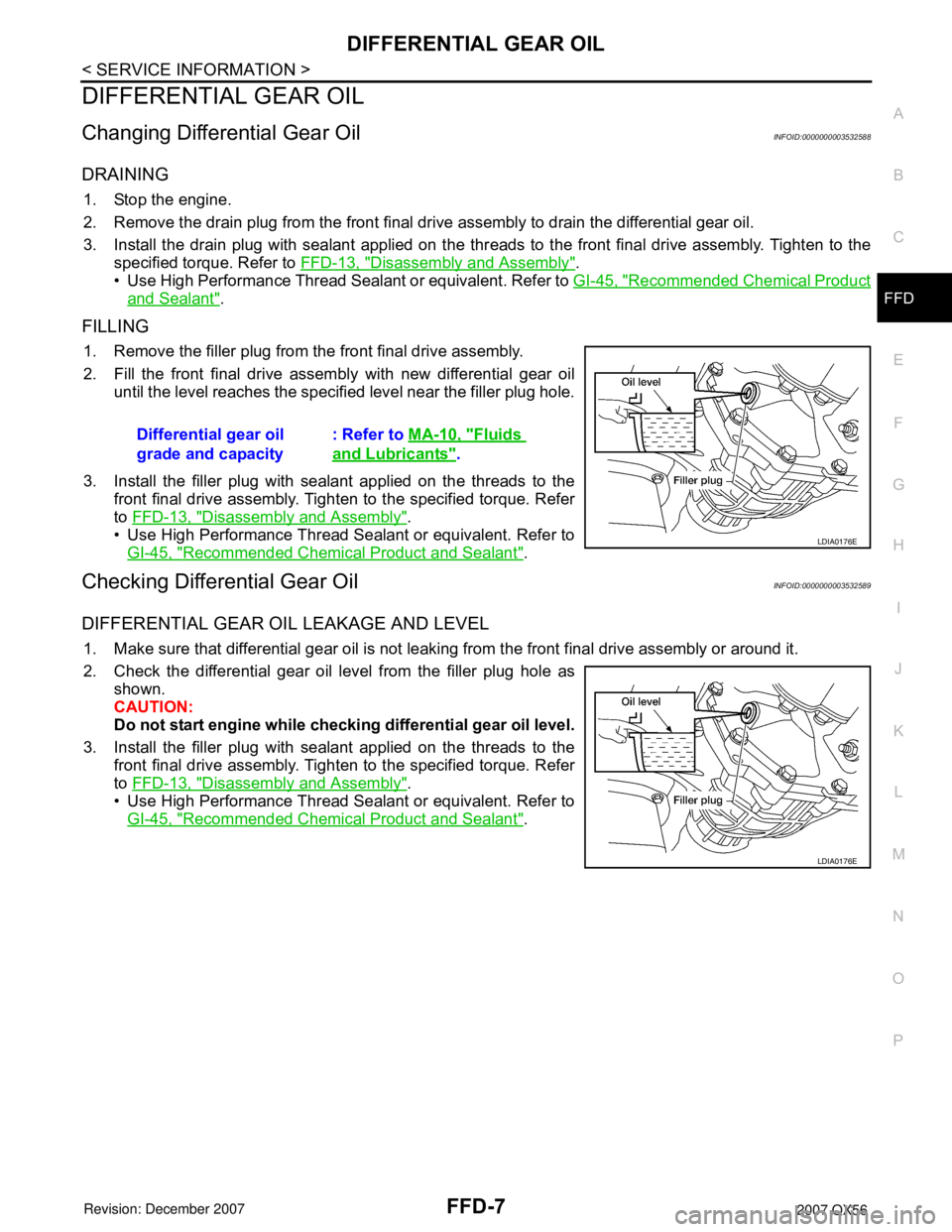
2. Fill the front final drive assembly with new differential gear oil
until the level reaches the specified level near the filler plug hole.
3. Install the filler plug with sealant applied on the threads to the
front final drive assembly. Tighten to the specified torque. Refer
to FFD-13, "
Disassembly and Assembly".
• Use High Performance Thread Sealant or equivalent. Refer to
GI-45, "
Recommended Chemical Product and Sealant".
Checking Differential Gear OilINFOID:0000000003532589
DIFFERENTIAL GEAR OIL LEAKAGE AND LEVEL
1. Make sure that differential gear oil is not leaking from the front final drive assembly or around it.
2. Check the differential gear oil level from the filler plug hole as
shown.
CAUTION:
Do not start engine while checking differential gear oil level.
3. Install the filler plug with sealant applied on the threads to the
front final drive assembly. Tighten to the specified torque. Refer
to FFD-13, "
Disassembly and Assembly".
• Use High Performance Thread Sealant or equivalent. Refer to
GI-45, "
Recommended Chemical Product and Sealant". Differential gear oil
grade and capacity: Refer to MA-10, "
Fluids
and Lubricants".
LDIA0176E
LDIA0176E
Page 1910 of 3061
CARRIER COVER
FFD-11
< SERVICE INFORMATION >
C
E
F
G
H
I
J
K
L
MA
B
FFD
N
O
P
CARRIER COVER
Removal and InstallationINFOID:0000000003532592
REMOVAL
1. Remove the front final drive assembly. Refer to FFD-12, "Removal and Installation".
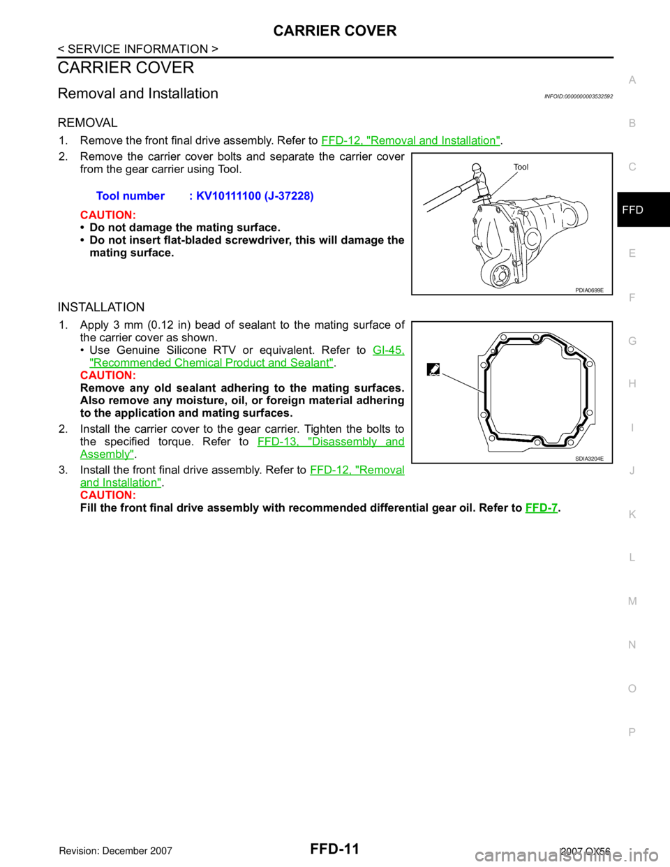
2. Remove the carrier cover bolts and separate the carrier cover
from the gear carrier using Tool.
CAUTION:
• Do not damage the mating surface.
• Do not insert flat-bladed screwdriver, this will damage the
mating surface.
INSTALLATION
1. Apply 3 mm (0.12 in) bead of sealant to the mating surface of
the carrier cover as shown.
• Use Genuine Silicone RTV or equivalent. Refer to GI-45,
"Recommended Chemical Product and Sealant".
CAUTION:
Remove any old sealant adhering to the mating surfaces.
Also remove any moisture, oil, or foreign material adhering
to the application and mating surfaces.
2. Install the carrier cover to the gear carrier. Tighten the bolts to
the specified torque. Refer to FFD-13, "
Disassembly and
Assembly".
3. Install the front final drive assembly. Refer to FFD-12, "
Removal
and Installation".
CAUTION:
Fill the front final drive assembly with recommended differential gear oil. Refer to FFD-7
. Tool number : KV10111100 (J-37228)
PDIA0699E
SDIA3204E
Page 1929 of 3061
FFD-30
< SERVICE INFORMATION >
FRONT FINAL DRIVE ASSEMBLY
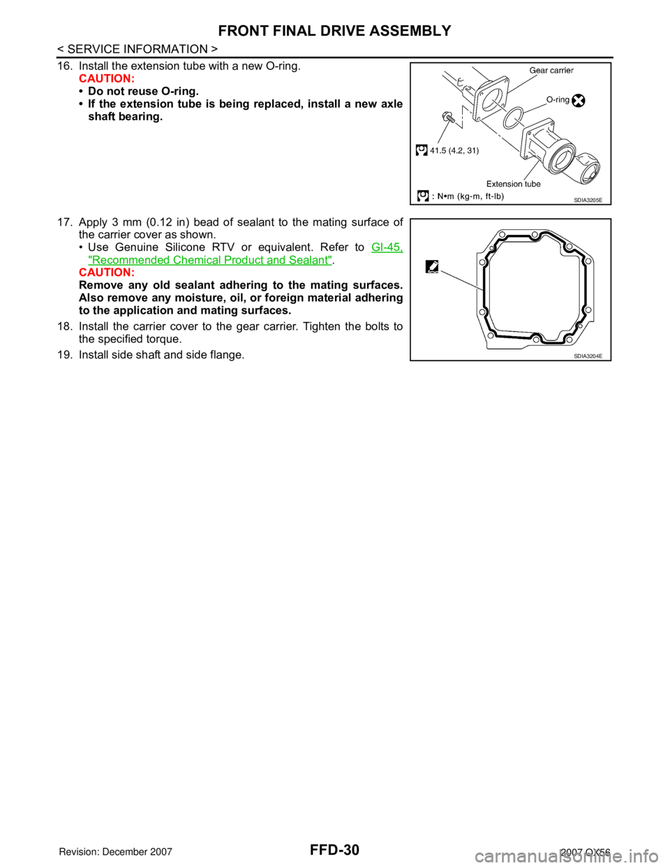
16. Install the extension tube with a new O-ring.
CAUTION:
• Do not reuse O-ring.
• If the extension tube is being replaced, install a new axle
shaft bearing.
17. Apply 3 mm (0.12 in) bead of sealant to the mating surface of
the carrier cover as shown.
• Use Genuine Silicone RTV or equivalent. Refer to GI-45,
"Recommended Chemical Product and Sealant".
CAUTION:
Remove any old sealant adhering to the mating surfaces.
Also remove any moisture, oil, or foreign material adhering
to the application and mating surfaces.
18. Install the carrier cover to the gear carrier. Tighten the bolts to
the specified torque.
19. Install side shaft and side flange.
SDIA3205E
SDIA3204E