2007 INFINITI QX56 oil change
[x] Cancel search: oil changePage 1232 of 3061
DTC P0011, P0021 IVT CONTROL
EC-149
< SERVICE INFORMATION >
C
D
E
F
G
H
I
J
K
L
MA
EC
N
P O
DTC P0011, P0021 IVT CONTROL
DescriptionINFOID:0000000003531648
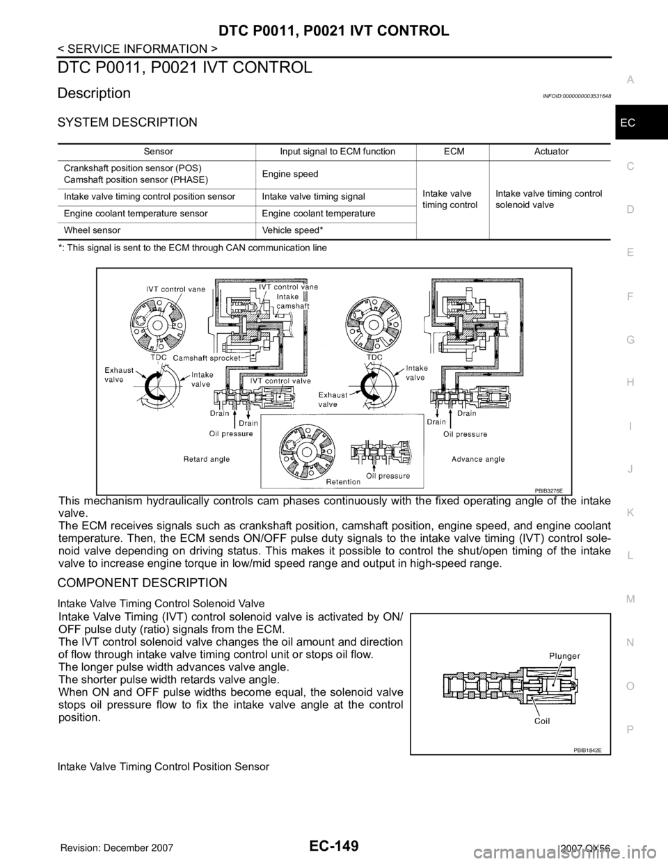
SYSTEM DESCRIPTION
*: This signal is sent to the ECM through CAN communication line
This mechanism hydraulically controls cam phases continuously with the fixed operating angle of the intake
valve.
The ECM receives signals such as crankshaft position, camshaft position, engine speed, and engine coolant
temperature. Then, the ECM sends ON/OFF pulse duty signals to the intake valve timing (IVT) control sole-
noid valve depending on driving status. This makes it possible to control the shut/open timing of the intake
valve to increase engine torque in low/mid speed range and output in high-speed range.
COMPONENT DESCRIPTION
Intake Valve Timing Control Solenoid Valve
Intake Valve Timing (IVT) control solenoid valve is activated by ON/
OFF pulse duty (ratio) signals from the ECM.
The IVT control solenoid valve changes the oil amount and direction
of flow through intake valve timing control unit or stops oil flow.
The longer pulse width advances valve angle.
The shorter pulse width retards valve angle.
When ON and OFF pulse widths become equal, the solenoid valve
stops oil pressure flow to fix the intake valve angle at the control
position.
Intake Valve Timing Control Position Sensor
Sensor Input signal to ECM function ECM Actuator
Crankshaft position sensor (POS)
Camshaft position sensor (PHASE)Engine speed
Intake valve
timing controlIntake valve timing control
solenoid valve Intake valve timing control position sensor Intake valve timing signal
Engine coolant temperature sensor Engine coolant temperature
Wheel sensor Vehicle speed*
PBIB3276E
PBIB1842E
Page 1261 of 3061
EC-178
< SERVICE INFORMATION >
DTC P0075, P0081 IVT CONTROL SOLENOID VALVE
DTC P0075, P0081 IVT CONTROL SOLENOID VALVE
Component DescriptionINFOID:0000000003531672
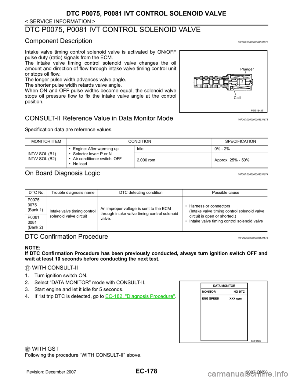
Intake valve timing control solenoid valve is activated by ON/OFF
pulse duty (ratio) signals from the ECM.
The intake valve timing control solenoid valve changes the oil
amount and direction of flow through intake valve timing control unit
or stops oil flow.
The longer pulse width advances valve angle.
The shorter pulse width retards valve angle.
When ON and OFF pulse widths become equal, the solenoid valve
stops oil pressure flow to fix the intake valve angle at the control
position.
CONSULT-II Reference Value in Data Monitor ModeINFOID:0000000003531673
Specification data are reference values.
On Board Diagnosis LogicINFOID:0000000003531674
DTC Confirmation ProcedureINFOID:0000000003531675
NOTE:
If DTC Confirmation Procedure has been previously conducted, always turn ignition switch OFF and
wait at least 10 seconds before conducting the next test.
WITH CONSULT-II
1. Turn ignition switch ON.
2. Select “DATA MONITOR” mode with CONSULT-II.
3. Start engine and let it idle for 5 seconds.
4. If 1st trip DTC is detected, go to EC-182, "
Diagnosis Procedure".
WITH GST
Following the procedure “WITH CONSULT-II” above.
PBIB1842E
MONITOR ITEM CONDITION SPECIFICATION
INT/V SOL (B1)
INT/V SOL (B2)• Engine: After warming up
• Selector lever: P or N
• Air conditioner switch: OFF
•No loadIdle 0% - 2%
2,000 rpm Approx. 25% - 50%
DTC No. Trouble diagnosis name DTC detecting condition Possible cause
P0075
0075
(Bank 1)
Intake valve timing control
solenoid valve circuitAn improper voltage is sent to the ECM
through intake valve timing control solenoid
valve.• Harness or connectors
(Intake valve timing control solenoid valve
circuit is open or shorted.)
• Intake valve timing control solenoid valve P0081
0081
(Bank 2)
SEF058Y
Page 1716 of 3061
IGNITION SIGNAL
EC-633
< SERVICE INFORMATION >
C
D
E
F
G
H
I
J
K
L
MA
EC
N
P O
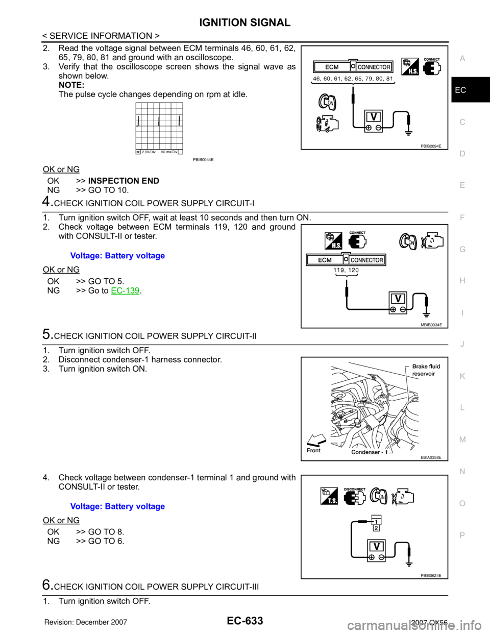
2. Read the voltage signal between ECM terminals 46, 60, 61, 62,
65, 79, 80, 81 and ground with an oscilloscope.
3. Verify that the oscilloscope screen shows the signal wave as
shown below.
NOTE:
The pulse cycle changes depending on rpm at idle.
OK or NG
OK >>INSPECTION END
NG >> GO TO 10.
4.CHECK IGNITION COIL POWER SUPPLY CIRCUIT-I
1. Turn ignition switch OFF, wait at least 10 seconds and then turn ON.
2. Check voltage between ECM terminals 119, 120 and ground
with CONSULT-II or tester.
OK or NG
OK >> GO TO 5.
NG >> Go to EC-139
.
5.CHECK IGNITION COIL POWER SUPPLY CIRCUIT-II
1. Turn ignition switch OFF.
2. Disconnect condenser-1 harness connector.
3. Turn ignition switch ON.
4. Check voltage between condenser-1 terminal 1 and ground with
CONSULT-II or tester.
OK or NG
OK >> GO TO 8.
NG >> GO TO 6.
6.CHECK IGNITION COIL POWER SUPPLY CIRCUIT-III
1. Turn ignition switch OFF.
PBIB2094E
PBIB0044E
Voltage: Battery voltage
MBIB0034E
BBIA0358E
Voltage: Battery voltage
PBIB0624E
Page 1812 of 3061
EM-42
< SERVICE INFORMATION >
TIMING CHAIN
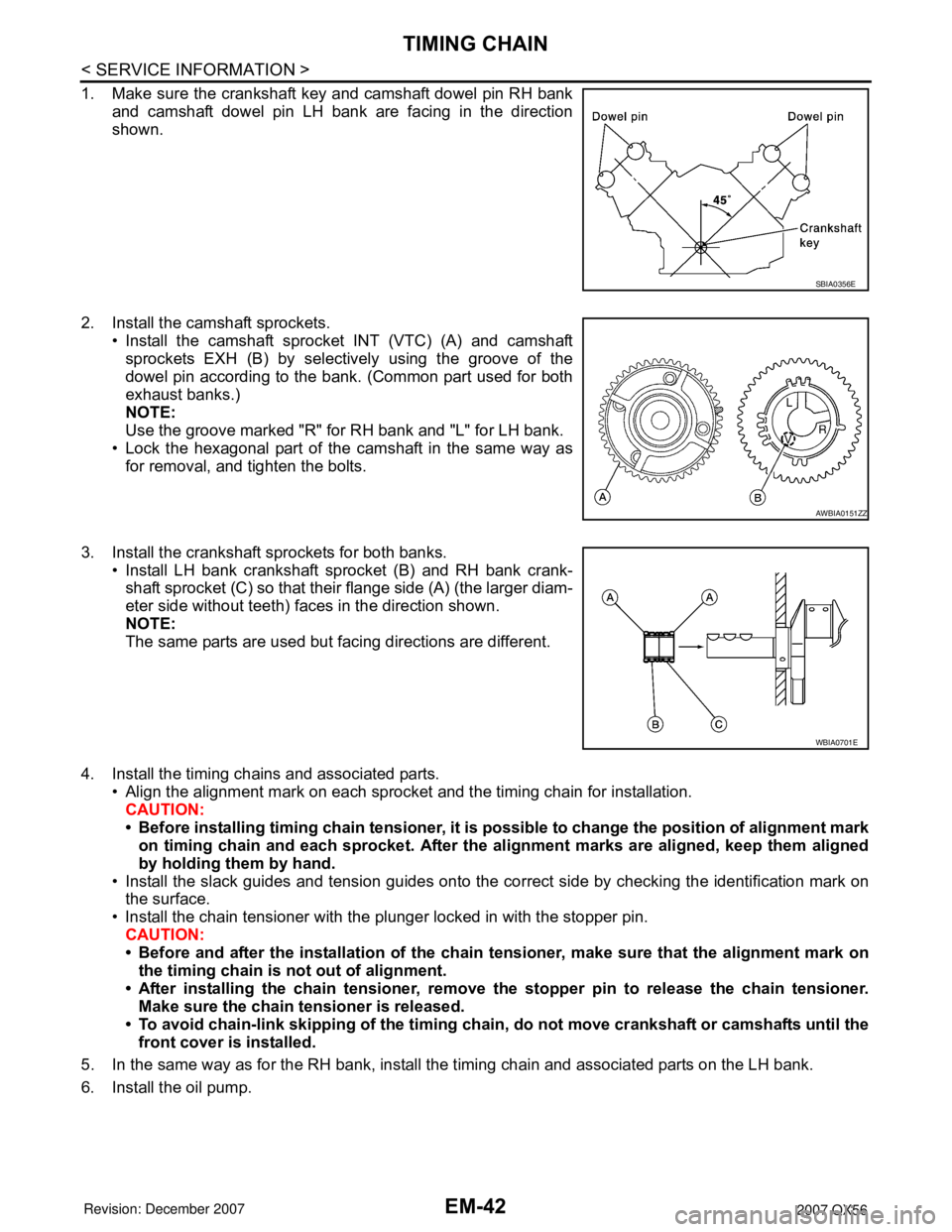
1. Make sure the crankshaft key and camshaft dowel pin RH bankand camshaft dowel pin LH bank are facing in the direction
shown.
2. Install the camshaft sprockets. • Install the camshaft sprocket INT (VTC) (A) and camshaftsprockets EXH (B) by selectively using the groove of the
dowel pin according to the bank . (Common part used for both
exhaust banks.)
NOTE:
Use the groove marked "R" for RH bank and "L" for LH bank.
• Lock the hexagonal part of the camshaft in the same way as for removal, and tighten the bolts.
3. Install the crankshaft sprockets for both banks. • Install LH bank crankshaft sprocket (B) and RH bank crank-shaft sprocket (C) so that their flange side (A) (the larger diam-
eter side without teeth) faces in the direction shown.
NOTE:
The same parts are used but facing directions are different.
4. Install the timing chains and associated parts. • Align the alignment mark on each sprocket and the timing chain for installation.
CAUTION:
• Before installing timing chain tens ioner, it is possible to change the position of alignment mark
on timing chain and each sprocket. After the al ignment marks are aligned, keep them aligned
by holding them by hand.
• Install the slack guides and tension guides onto the co rrect side by checking the identification mark on
the surface.
• Install the chain tensioner with the plunger locked in with the stopper pin.
CAUTION:
• Before and after the installation of the chain tensioner, make sure that the alignment mark on
the timing chain is not out of alignment.
• After installing the chain tensioner, remove the stopper pin to release the chain tensioner.
Make sure the chain tensioner is released.
• To avoid chain-link skipping of the timing chain, do not move crankshaft or camshafts until the
front cover is installed.
5. In the same way as for the RH bank, install the timing chain and associated parts on the LH bank.
6. Install the oil pump.
SBIA0356E
AWBIA0151ZZ
WBIA0701E
Page 1826 of 3061
EM-56
< SERVICE INFORMATION >
CAMSHAFT
2. Perform the following procedure so as to prevent the engine from being unintentionally started while
checking.
a. Release fuel pressure. Refer to EC-80, "
Fuel Pressure Check".
b. Disconnect ignition coil and injector harness connectors if practical.
3. Remove IVT control solenoid valve.
4. Crank engine, and then make sure that engine oil comes out from IVT control cover oil hole. End cranking
after checking.
WARNING:
Be careful not to touch rotating parts (drive be lts, idler pulley, and crankshaft pulley, etc.).
CAUTION:
• Engine oil may squirt from IVT control soleno id valve installation hole during cranking. Use a
shop cloth to prevent engine oil from splashin g on worker, engine components and vehicle.
• Do not allow engine oil to get on rubber compon ents such as drive belts or engine mount insula-
tors. Immediately wipe off any splashed engine oil.
5. Clean oil groove between oil strainer and IVT control solenoid valve if engine oil does not come out from IVT control valve cover oil hole. Refer to LU-7, "
Schematic".
6. Remove components between IVT control solenoid va lve and camshaft sprocket (INT), and then check
each oil groove for clogging.
• Clean oil groove if necessary.
7. After inspection, installation of the remaining components is in the reverse order of removal.
Valve ClearanceINFOID:0000000003531536
INSPECTION
NOTE:
Perform the following inspection after removal, installation or replacement of camshaft or valve-related parts,
or if there are unusual engine conditions due to changes in valve clearance over time (starting, idling, and/or
noise).
1. Warm up the engine. Then stop the engine.
2. Remove the engine cover and. Refer to EM-12, "
Removal and Installation".
3. Remove the battery cover. Refer to SC-8, "
Removal and Installation".
4. Remove the air cleaner and air duct assembly EM-15, "
Removal and Installation".
5. Remove the RH bank and LH bank rocker covers using power tool. Refer to EM-35, "
Removal and Instal-
lation".
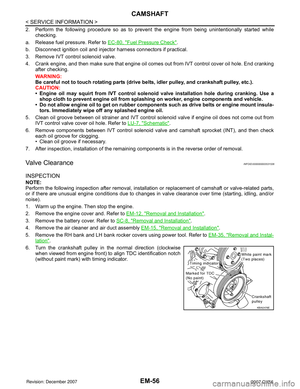
6. Turn the crankshaft pulley in the normal direction (clockwise when viewed from engine front) to align TDC identification notch
(without paint mark) with timing indicator.
KBIA2476E
Page 1916 of 3061
FRONT FINAL DRIVE ASSEMBLY
FFD-17
< SERVICE INFORMATION >
C
E
F
G
H
I
J
K
L
MA
B
FFD
N
O
P Backlash
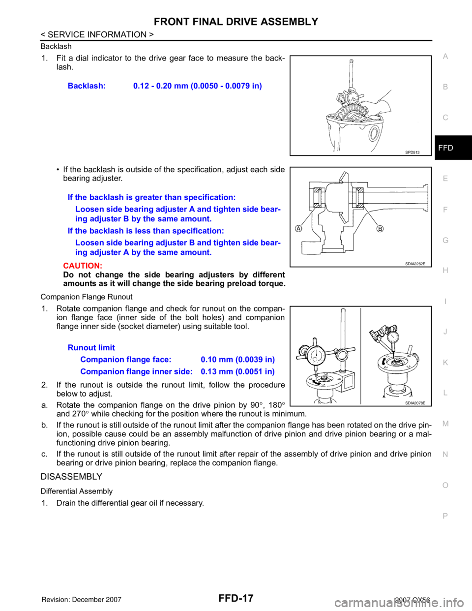
1. Fit a dial indicator to the drive gear face to measure the back-
lash.
• If the backlash is outside of the specification, adjust each side
bearing adjuster.
CAUTION:
Do not change the side bearing adjusters by different
amounts as it will change the side bearing preload torque.
Companion Flange Runout
1. Rotate companion flange and check for runout on the compan-
ion flange face (inner side of the bolt holes) and companion
flange inner side (socket diameter) using suitable tool.
2. If the runout is outside the runout limit, follow the procedure
below to adjust.
a. Rotate the companion flange on the drive pinion by 90°, 180°
and 270° while checking for the position where the runout is minimum.
b. If the runout is still outside of the runout limit after the companion flange has been rotated on the drive pin-
ion, possible cause could be an assembly malfunction of drive pinion and drive pinion bearing or a mal-
functioning drive pinion bearing.
c. If the runout is still outside of the runout limit after repair of the assembly of drive pinion and drive pinion
bearing or drive pinion bearing, replace the companion flange.
DISASSEMBLY
Differential Assembly
1. Drain the differential gear oil if necessary.Backlash: 0.12 - 0.20 mm (0.0050 - 0.0079 in)
SPD513
If the backlash is greater than specification:
Loosen side bearing adjuster A and tighten side bear-
ing adjuster B by the same amount.
If the backlash is less than specification:
Loosen side bearing adjuster B and tighten side bear-
ing adjuster A by the same amount.
SDIA2262E
Runout limit
Companion flange face: 0.10 mm (0.0039 in)
Companion flange inner side: 0.13 mm (0.0051 in)
SDIA2078E
Page 1999 of 3061
SERVICE INFORMATION FOR ELECTRICAL INCIDENT
GI-33
< SERVICE INFORMATION >
C
D
E
F
G
H
I
J
K
L
MB
GI
N
O
P
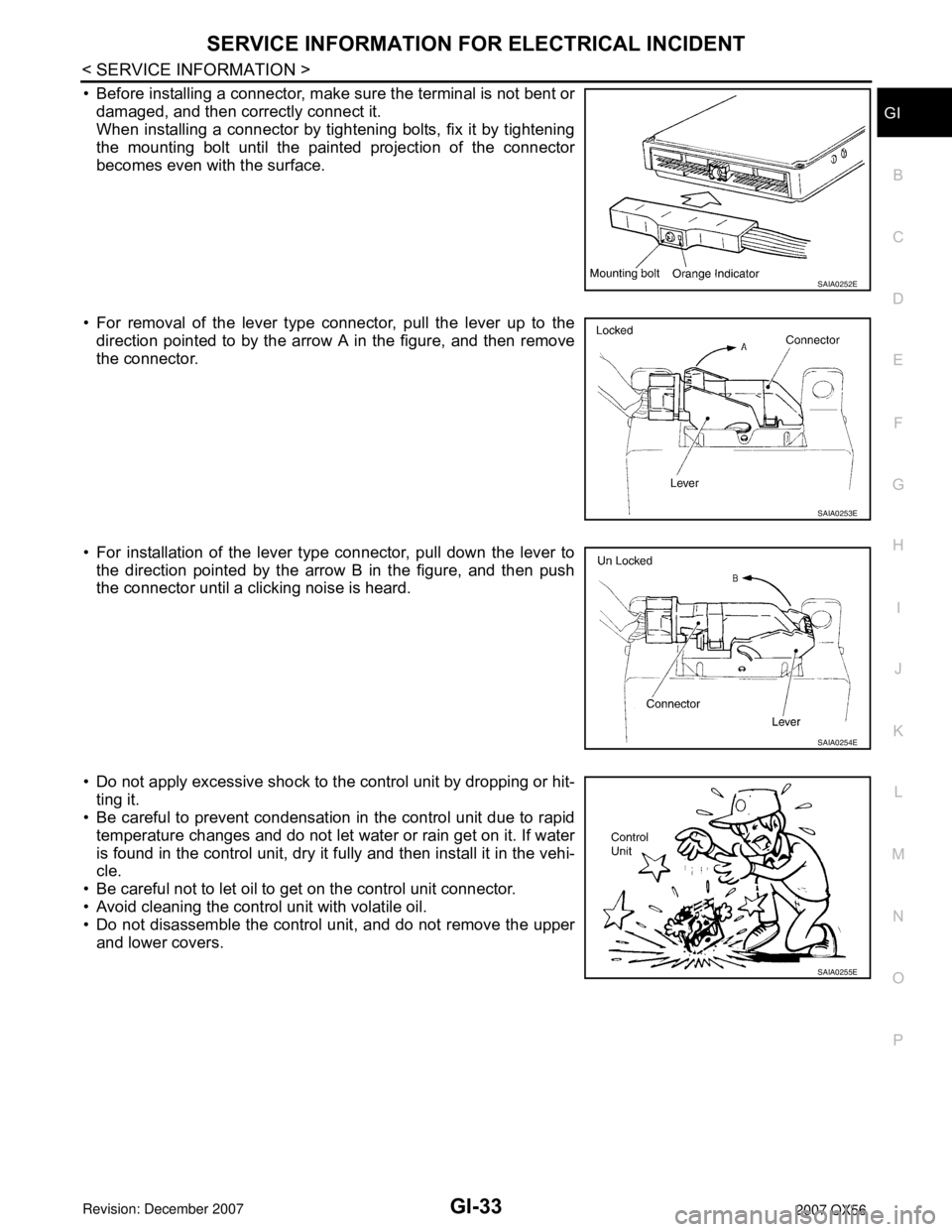
• Before installing a connector, make sure the terminal is not bent or
damaged, and then correctly connect it.
When installing a connector by tightening bolts, fix it by tightening
the mounting bolt until the painted projection of the connector
becomes even with the surface.
• For removal of the lever type connector, pull the lever up to the
direction pointed to by the arrow A in the figure, and then remove
the connector.
• For installation of the lever type connector, pull down the lever to
the direction pointed by the arrow B in the figure, and then push
the connector until a clicking noise is heard.
• Do not apply excessive shock to the control unit by dropping or hit-
ting it.
• Be careful to prevent condensation in the control unit due to rapid
temperature changes and do not let water or rain get on it. If water
is found in the control unit, dry it fully and then install it in the vehi-
cle.
• Be careful not to let oil to get on the control unit connector.
• Avoid cleaning the control unit with volatile oil.
• Do not disassemble the control unit, and do not remove the upper
and lower covers.
SAIA0252E
SAIA0253E
SAIA0254E
SAIA0255E
Page 2213 of 3061

LT-6
< SERVICE INFORMATION >
HEADLAMP (FOR USA)
• to BCM terminal 38.
Ground is supplied
• to BCM terminal 67
• through grounds M57, M61 and M79, and
• to IPDM E/R terminals 38 and 59
• through grounds E9, E15 and E24.
Low Beam Operation
With the lighting switch in 2ND position, the BCM receives input requesting the headlamps to illuminate. This
input is communicated to the IPDM E/R across the CAN communication lines. The CPU of the IPDM E/R con-
trols the headlamp low relay coil. When energized, this relay directs power
• through 15A fuse (No. 41, located in the IPDM E/R)
• through IPDM E/R terminal 54
• to front combination lamp RH terminal 5, and
• through 15A fuse (No. 40, located in the IPDM E/R)
• through IPDM E/R terminal 52
• to front combination lamp LH terminal 5.
Ground is supplied
• to front combination lamp LH and RH terminal 1
• through grounds E9, E15 and E24.
With power and ground supplied, low beam headlamps illuminate.
High Beam Operation/Flash-to-Pass Operation
With the lighting switch in 2ND position and placed in HIGH or PASS position, the BCM receives input request-
ing the headlamp high beams to illuminate. This input is communicated to the IPDM E/R across the CAN com-
munication lines. The CPU of the combination meter controls the ON/OFF status of the HIGH BEAM indicator.
The CPU of the IPDM E/R controls the headlamp high relay coil. When energized, this relay directs power
• through 10A fuse (No. 34, located in the IPDM E/R)
• through IPDM E/R terminal 56
• to front combination lamp RH terminal 6, and
• through 10A fuse (No. 35, located in the IPDM E/R)
• through IPDM E/R terminal 55
• to front combination lamp LH terminal 6.
Ground is supplied
• to front combination lamp LH and RH terminal 2
• through grounds E9, E15 and E24.
With power and ground supplied, the high beam headlamps illuminate.
XENON HEADLAMP
Xenon type headlamp is adopted to the low beam headlamps. Xenon bulbs do not use a filament. Instead,
they produce light when a high voltage current is passed between two tungsten electrodes through a mixture
of xenon (an inert gas) and certain other metal halides. In addition to added lighting power, electronic control
of the power supply gives the headlamps stable quality and tone color.
Following are some of the many advantages of the xenon type headlamp.
• The light produced by the headlamps is a white color comparable to sunlight that is easy on the eyes.
• Light output is nearly double that of halogen headlamps, affording increased area of illumination.
• The light features a high relative spectral distribution at wavelengths to which the human eye is most sensi-
tive. This means that even in the rain, more light is reflected back from the road surface toward the vehicle,
for added visibility.
• Power consumption is approximately 25 percent less than halogen headlamps, reducing battery load.
BATTERY SAVER CONTROL
When the combination switch (lighting switch) is in the 2ND position (ON), and the ignition switch is turned
from ON or ACC to OFF, the battery saver control feature is activated.
Under this condition, the headlamps remain illuminated for 5 minutes, unless the combination switch (lighting
switch) position is changed. If the combination switch (lighting switch) position is changed, then the headlamps
are turned off.
AUTO LIGHT OPERATION
Refer to LT-34, "System Description" for auto light operation.
VEHICLE SECURITY SYSTEM (PANIC ALARM)