2007 INFINITI QX56 drain bolt
[x] Cancel search: drain boltPage 918 of 3061

BR-20
< SERVICE INFORMATION >
FRONT DISC BRAKE
4. Remove disc rotor.
INSTALLATION
CAUTION:
• Refill with new brake fluid. Refer to MA-10
.
• Do not reuse drained brake fluid.
1. Install disc rotor.
2. Install sliding pin bolts and torque member to caliper, if removed. Refer to BR-18, "
Component" .
3. Install caliper assembly to the vehicle, then tighten the torque
member bolts to the specified torque. Refer to BR-18, "
Compo-
nent" .
CAUTION:
• When attaching caliper assembly to the vehicle, wipe any
oil off knuckle spindle, washers and caliper assembly
attachment surfaces.
• Do not reuse caliper torque member bolts.
4. Install brake hose to cylinder body, then tighten union bolt to
specification, as necessary. Refer to BR-18, "
Component" .
CAUTION:
• Do not reuse copper washer.
• Install brake hose to caliper assembly together with union
bolt and washers.
5. Refill with new brake fluid and bleed air. Refer to BR-8, "
Bleeding Brake System" .
6. Install tires to the vehicle. Refer to WT-7, "
Rotation" .
Disassembly and Assembly of Brake CaliperINFOID:0000000003532742
DISASSEMBLY
1. Remove sliding pin bolt, and then remove the pad, shim, shim cover, and pad retainer from the torque
member.
2. Remove sliding pins and sliding pin boots from torque member.
3. Place a wooden block as shown, and blow air from union bolt
mounting hole to remove pistons and piston boots.
CAUTION:
Keep hands away from piston.
LFIA0209E
LFIA0214E
BRB0032D
Page 923 of 3061

REAR DISC BRAKE
BR-25
< SERVICE INFORMATION >
C
D
E
G
H
I
J
K
L
MA
B
BR
N
O
P
WARNING:
Clean dust on caliper and brake pad with a vacuum dust collector to minimize the hazard of airborne
particles or other materials.
CAUTION:
• While removing cylinder body, never depress brake pedal because piston will pop out.
• It is not necessary to remove bolts on torque member and brake hose except for disassembly or
replacement of cylinder body. In this case, hang cylinder body with a wire so as not to stretch brake
hose.
• Do not damage piston boot.
• Burnish brake contact surface after refinishing or replacing rotors, after replacing pads, or it a soft
pedal occurs at very low mileage. Refer to BR-26, "
Brake Caliper" .
Removal and Installation of Brake PadINFOID:0000000003532745
REMOVAL
1. Remove tires from vehicle with power tool.
2. Remove the top bolt from the cylinder body.
3. Swing cylinder body open, and remove pads.
INSTALLATION
1. Push piston in so that pad is firmly attached and install cylinder body to torque member.
NOTE:
Using a disc brake piston tool (commercial service tool), makes it easier to push in the piston.
CAUTION:
By pushing in piston, brake fluid returns to master cylinder reservoir tank. Watch the level of the
surface of reservoir tank.
2. Apply Molykote M-77 grease to knuckle slide where brake pad contacts.
CAUTION:
Do not get grease on the brake rotor friction surface.
3. Install pads to cylinder body.
4. Install cylinder body top bolt and tighten to specification.
5. Check brake for drag.
6. Install tires to the vehicle. Refer to WT-7, "
Rotation" .
Removal and Installation of Brake Caliper and Disc RotorINFOID:0000000003532746
REMOVAL
1. Remove tires from vehicle with power tool.
2. Drain brake fluid as necessary. Refer to BR-8, "
Drain and Refill" .
NOTE:
Do not remove union bolt unless removing cylinder body from vehicle.
3. Remove mounting bolts and cylinder body.
NOTE:
Position cylinder body aside using suitable wire, as necessary.
4. Remove disc rotor.
INSTALLATION
CAUTION:
• Refill with new brake fluid. Refer to MA-10
.
• Do not reuse drained brake fluid.
1. Install disc rotor.
LFIA0211E
Page 986 of 3061
![INFINITI QX56 2007 Factory Service Manual BRC-58
< SERVICE INFORMATION >[VDC/TCS/ABS]
ACTUATOR AND ELECTRIC UNIT (ASSEMBLY)
ACTUATOR AND ELECTRIC UNIT (ASSEMBLY)
Removal and InstallationINFOID:0000000003532813
REMOVAL
1. Disconnect the negati INFINITI QX56 2007 Factory Service Manual BRC-58
< SERVICE INFORMATION >[VDC/TCS/ABS]
ACTUATOR AND ELECTRIC UNIT (ASSEMBLY)
ACTUATOR AND ELECTRIC UNIT (ASSEMBLY)
Removal and InstallationINFOID:0000000003532813
REMOVAL
1. Disconnect the negati](/manual-img/42/57029/w960_57029-985.png)
BRC-58
< SERVICE INFORMATION >[VDC/TCS/ABS]
ACTUATOR AND ELECTRIC UNIT (ASSEMBLY)
ACTUATOR AND ELECTRIC UNIT (ASSEMBLY)
Removal and InstallationINFOID:0000000003532813
REMOVAL
1. Disconnect the negative battery terminal.
2. Remove the cowl top extension. Refer to EI-17, "
Removal and Installation" .
3. Drain the brake fluid. Refer to BR-8, "
Drain and Refill".
4. Disconnect the actuator harness from the ABS actuator and electric unit (control unit).
CAUTION:
• To remove the brake tubes, use a flare nut wrench to prevent the flare nuts and brake tubes from
being damaged.
• Be careful not to splash brake fluid on painted areas; it may cause paint damage. If brake fluid is
splashed on painted areas, wash it away with water immediately.
5. Disconnect the brake tubes.
6. Remove the three bolts and remove the ABS actuator and electric unit (control unit).
INSTALLATION
Installation is in the reverse order of removal.
NOTE:
To install, use a flare nut wrench (commercial service tool). Tighten brake tubes to specification when install-
ing. Refer to BR-10, "
Hydraulic Circuit" .
1. To left front 2. To rear right 3. To rear left
4. To front right 5. From the master cylinder secondary
side6. From the master cylinder primary
side
7. ABS actuator and electric unit (con-
trol unit)8. Harness connector
WFIA0375E
Page 1002 of 3061
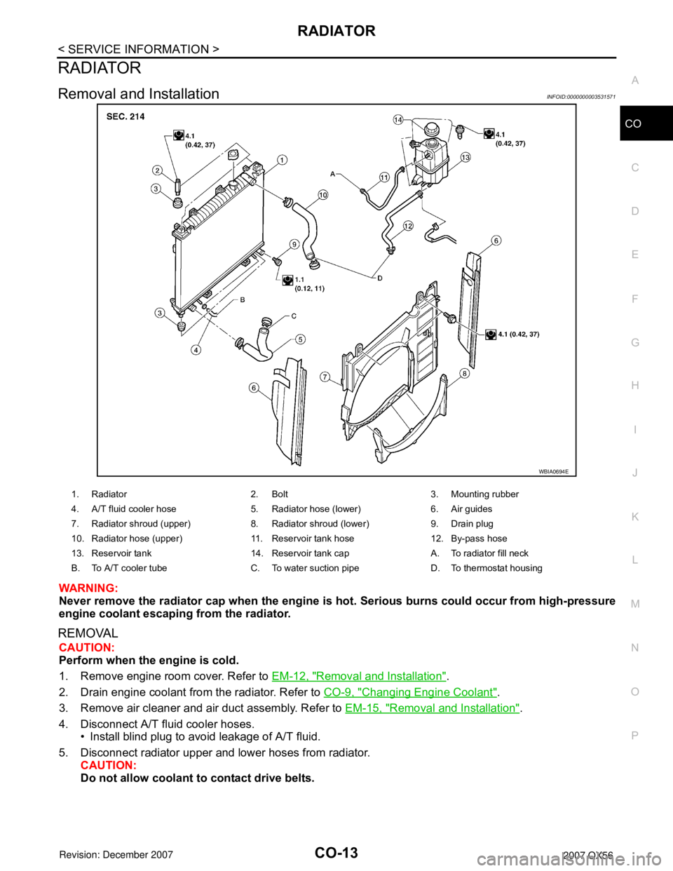
RADIATOR
CO-13
< SERVICE INFORMATION >
C
D
E
F
G
H
I
J
K
L
MA
CO
N
P O
RADIATOR
Removal and InstallationINFOID:0000000003531571
WARNING:
Never remove the radiator cap when the engine is hot. Serious burns could occur from high-pressure
engine coolant escaping from the radiator.
REMOVAL
CAUTION:
Perform when the engine is cold.
1. Remove engine room cover. Refer to EM-12, "
Removal and Installation".
2. Drain engine coolant from the radiator. Refer to CO-9, "
Changing Engine Coolant".
3. Remove air cleaner and air duct assembly. Refer to EM-15, "
Removal and Installation".
4. Disconnect A/T fluid cooler hoses.
• Install blind plug to avoid leakage of A/T fluid.
5. Disconnect radiator upper and lower hoses from radiator.
CAUTION:
Do not allow coolant to contact drive belts.
WBIA0694E
1. Radiator 2. Bolt 3. Mounting rubber
4. A/T fluid cooler hose 5. Radiator hose (lower) 6. Air guides
7. Radiator shroud (upper) 8. Radiator shroud (lower) 9. Drain plug
10. Radiator hose (upper) 11. Reservoir tank hose 12. By-pass hose
13. Reservoir tank 14. Reservoir tank cap A. To radiator fill neck
B. To A/T cooler tube C. To water suction pipe D. To thermostat housing
Page 1773 of 3061
PRECAUTIONSEM-3
< SERVICE INFORMATION >
C
DE
F
G H
I
J
K L
M A
EM
NP
O
SERVICE INFORMATION
PRECAUTIONS
Precaution for Supplemental
Restraint System (SRS) "AIR BAG" and "SEAT BELT
PRE-TENSIONER"
INFOID:0000000003531508
The Supplemental Restraint System such as “A IR BAG” and “SEAT BELT PRE-TENSIONER”, used along
with a front seat belt, helps to reduce the risk or severi ty of injury to the driver and front passenger for certain
types of collision. This system includes seat belt switch inputs and dual stage front air bag modules. The SRS
system uses the seat belt switches to determine the front air bag deployment, and may only deploy one front
air bag, depending on the severity of a collision and w hether the front occupants are belted or unbelted.
Information necessary to service the system safely is included in the SRS and SB section of this Service Man-
ual.
WARNING:
• To avoid rendering the SRS inoper ative, which could increase the risk of personal injury or death in
the event of a collision which would result in air bag inflation, all maintenance must be performed by
an authorized NISSAN/INFINITI dealer.
• Improper maintenance, including in correct removal and installation of the SRS, can lead to personal
injury caused by unintentional act ivation of the system. For removal of Spiral Cable and Air Bag
Module, see the SRS section.
• Do not use electrical test equipm ent on any circuit related to the SRS unless instructed to in this
Service Manual. SRS wiring harnesses can be identi fied by yellow and/or orange harnesses or har-
ness connectors.
Precaution for Drain Engine CoolantINFOID:0000000003531509
Drain engine coolant when engine is cooled.
Precaution for Disco nnecting Fuel PipingINFOID:0000000003531510
• Before starting work, make sure no fire or spark producing items are in the work area.
• Release fuel pressure before disconnecting and disassembly.
• After disconnecting pipes, plug openings to stop fuel leakage.
Precaution for Removal and DisassemblyINFOID:0000000003531511
• When instructed to use special service tools, use the spec ified tools. Always be careful to work safely, avoid
forceful or uninstructed operations.
• Exercise maximum care to avoid damage to mating or sliding surfaces.
• Cover openings of engine system with tape or the equiva lent, if necessary, to seal out foreign materials.
• Mark and arrange disassembly parts in an organized way for easy troubleshooting and assembly.
• When loosening nuts and bolts, as a basic rule, start with the one furthest outside, then the one diagonally
opposite, and so on. If the order of loosening is specif ied, do exactly as specified. Power tools may be used
where noted in the step.
Precaution for Inspection, Repair and ReplacementINFOID:0000000003531512
Before repairing or replacing, thoroughly inspect parts. Inspect new replacement parts in the same way, and
replace if necessary.
Precaution for Assembly and InstallationINFOID:0000000003531513
• Use torque wrench to tighten bolts or nuts to specification.
• When tightening nuts and bolts, as a basic rule, equally tighten in several different steps starting with the ones in center, then ones on inside and outside diagonally in this order. If the order of tightening is specified,
do exactly as specified.
• Replace with new gasket, packing, oil seal or O-ring.
• Thoroughly wash, clean, and air-blow each part. Carefully check engine oil or engine coolant passages for any restriction and blockage.
• Avoid damaging sliding or mating surfaces. Completely remove foreign materials such as cloth lint or dust. Before assembly, oil sliding surfaces well.
Page 1774 of 3061
EM-4
< SERVICE INFORMATION >
PRECAUTIONS
• Release air within route when refilling after draining engine coolant.
• Before starting engine, apply fuel pressure to fuel lines with turning ignition switch ON (with engine stopped).
Then make sure that there are no leaks at fuel line connections.
• After repairing, start engine and increase engine s peed to check engine coolant, fuel, oil, and exhaust sys-
tems for leakage.
Parts Requiring Angular TighteningINFOID:0000000003531514
• For final tightening of the following engine parts use Tool:
- Cylinder head bolts
- Main bearing cap bolts
- Connecting rod cap bolts
- Crankshaft pulley bolt (No angle wrench is required as the bolt flange is provided with notches for angle tightening)
• Do not use a torque value for final tightening.
• The torque value for these parts are for a preliminary step.
• Ensure thread and seat surfaces are clean and lightly coated with engine oil.
Precaution for Liquid GasketINFOID:0000000003531515
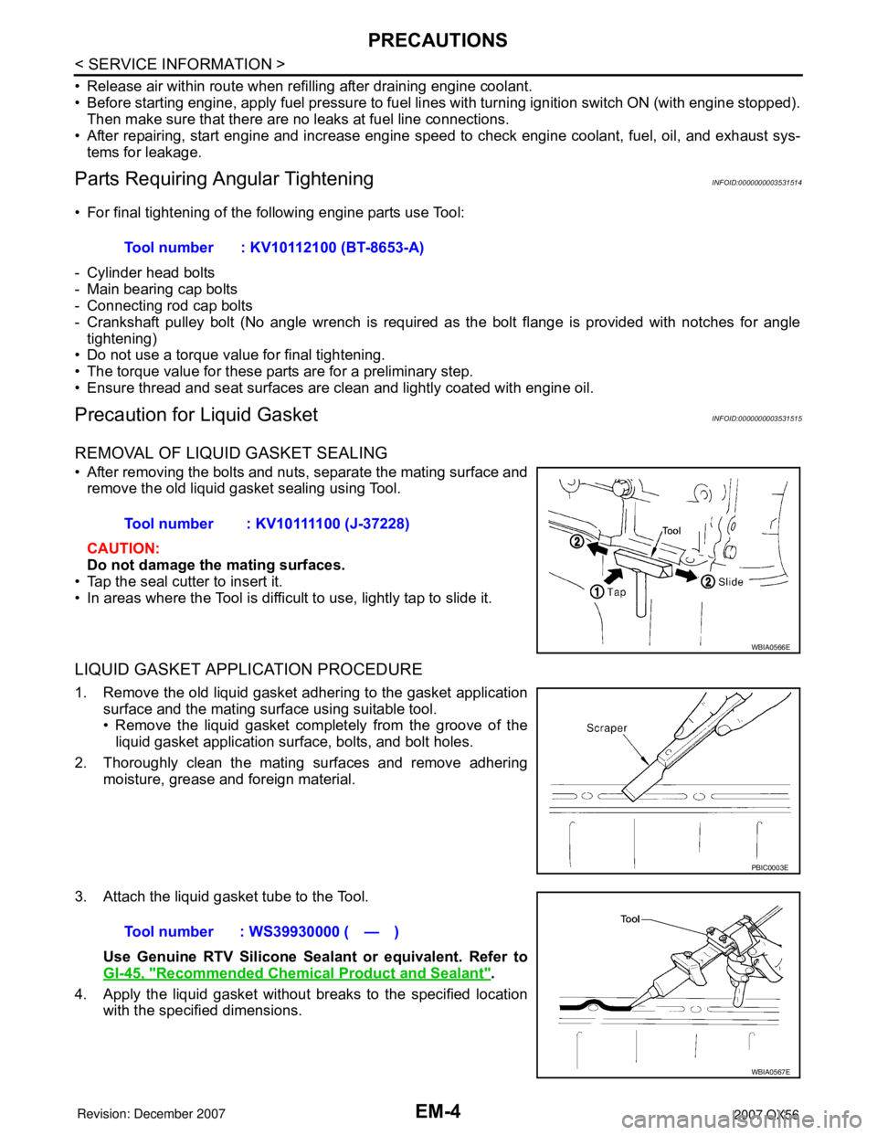
REMOVAL OF LIQUID GASKET SEALING
• After removing the bolts and nuts, separate the mating surface and
remove the old liquid gasket sealing using Tool.
CAUTION:
Do not damage the mating surfaces.
• Tap the seal cutter to insert it.
• In areas where the Tool is difficult to use, lightly tap to slide it.
LIQUID GASKET APPLICATION PROCEDURE
1. Remove the old liquid gasket adhering to the gasket application surface and the mating surface using suitable tool.
• Remove the liquid gasket completely from the groove of theliquid gasket application surface, bolts, and bolt holes.
2. Thoroughly clean the mating surfaces and remove adhering moisture, grease and foreign material.
3. Attach the liquid gasket tube to the Tool. Use Genuine RTV Silicone Seal ant or equivalent. Refer to
GI-45, "
Recommended Chemical Product and Sealant".
4. Apply the liquid gasket without breaks to the specified location with the specified dimensions.Tool number : KV10112100 (BT-8653-A)
Tool number : KV10111100 (J-37228)
WBIA0566E
PBIC0003E
Tool number : WS39930000 ( — )
WBIA0567E
Page 1794 of 3061
EM-24
< SERVICE INFORMATION >
OIL PAN AND OIL STRAINER
OIL PAN AND OIL STRAINER
Removal and InstallationINFOID:0000000003531528
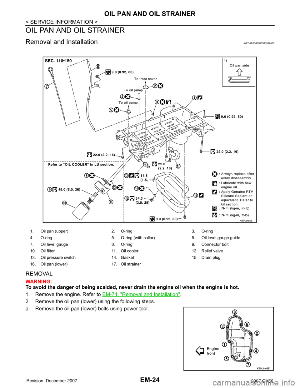
REMOVAL
WARNING:
To avoid the danger of being scalded, never drain the engine oil when the engine is hot.
1. Remove the engine. Refer to EM-74, "
Removal and Installation".
2. Remove the oil pan (lower) using the following steps.
a. Remove the oil pan (lower) bolts using power tool.
1. Oil pan (upper) 2. O-ring 3. O-ring
4. O-ring 5. O-ring (with collar) 6. Oil level gauge guide
7. Oil level gauge 8. O-ring 9. Connector bolt
10. Oil filter 11. Oil cooler 12. Relief valve
13. Oil pressure switch 14. Gasket 15. Drain plug
16. Oil pan (lower) 17. Oil strainer
KBIA2465E
KBIA2466E
Page 1844 of 3061
EM-74
< SERVICE INFORMATION >
ENGINE ASSEMBLY
ENGINE ASSEMBLY
Removal and InstallationINFOID:0000000003531544
WARNING:
• Situate vehicle on a flat and solid surface.
• Place chocks at front and back of rear wheels.
• For engines not equipped with engine slingers, attach proper slingers and bolts described in PARTS
CATALOG.
CAUTION:
• Always be careful to work safely, avoid forceful or uninstructed operations.
• Do not start working until exhaust system and engine coolant are cooled sufficiently.
• If items or work required are not covered by the engine section, refer to the applicable sections.
• Always use the support point specified for lifting.
• Use either 2-point lift type or separate type lift. If board-on type is used for unavoidable reasons,
support at the rear axle jacking point with transmission jack or similar tool before starting work, in
preparation for the backward shift of center of gravity.
• For supporting points for lifting and jacking point at rear axle, refer to GI-40, "
Garage Jack and
Safety Stand".
REMOVAL
Preparation
1. Drain the engine coolant. Refer to CO-9, "Changing Engine Coolant".
2. Partially drain the A/T fluid. Refer to AT-13, "
Changing Automatic Transmission Fluid (ATF)".
3. Release the fuel pressure. Refer to EC-80, "
Fuel Pressure Check".
4. Remove the engine hood. Refer to BL-12, "
Removal and Installation of Hood Assembly".
5. Remove the cowl extension. Refer to EI-17, "
Removal and Installation".
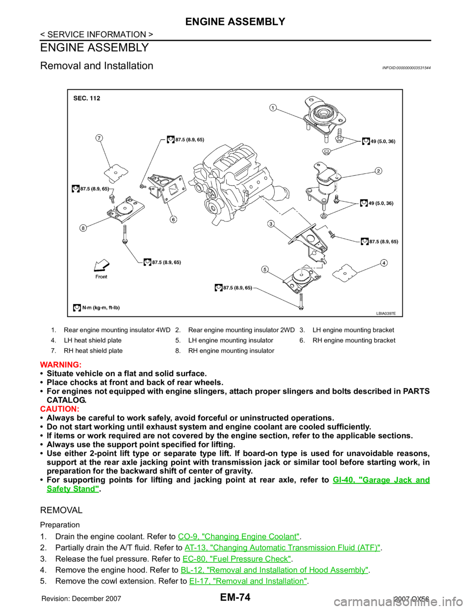
1. Rear engine mounting insulator 4WD 2. Rear engine mounting insulator 2WD 3. LH engine mounting bracket
4. LH heat shield plate 5. LH engine mounting insulator 6. RH engine mounting bracket
7. RH heat shield plate 8. RH engine mounting insulator
LBIA0397E