2007 INFINITI QX56 ECU
[x] Cancel search: ECUPage 2556 of 3061
RF-24
< SERVICE INFORMATION >
SUNROOF
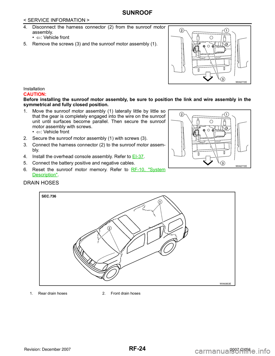
4. Disconnect the harness connector (2) from the sunroof motor
assembly.
•⇐: Vehicle front
5. Remove the screws (3) and the sunroof motor assembly (1).
Installation
CAUTION:
Before installing the sunroof motor assembly, be sure to position the link and wire assembly in the
symmetrical and fully closed position.
1. Move the sunroof motor assembly (1) laterally little by little so
that the gear is completely engaged into the wire on the sunroof
unit until surfaces become parallel. Then secure the sunroof
motor assembly with screws.
•⇐: Vehicle front
2. Secure the sunroof motor assembly (1) with screws (3).
3. Connect the harness connector (2) to the sunroof motor assem-
bly.
4. Install the overhead console assembly. Refer to EI-37
.
5. Connect the battery positive and negative cables.
6. Reset the sunroof motor memory. Refer to RF-10, "
System
Description".
DRAIN HOSES
WIIA0772E
WIIA0772E
1. Rear drain hoses 2. Front drain hoses
WIIA0853E
Page 2561 of 3061
RFD-4
< SERVICE INFORMATION >
PREPARATION
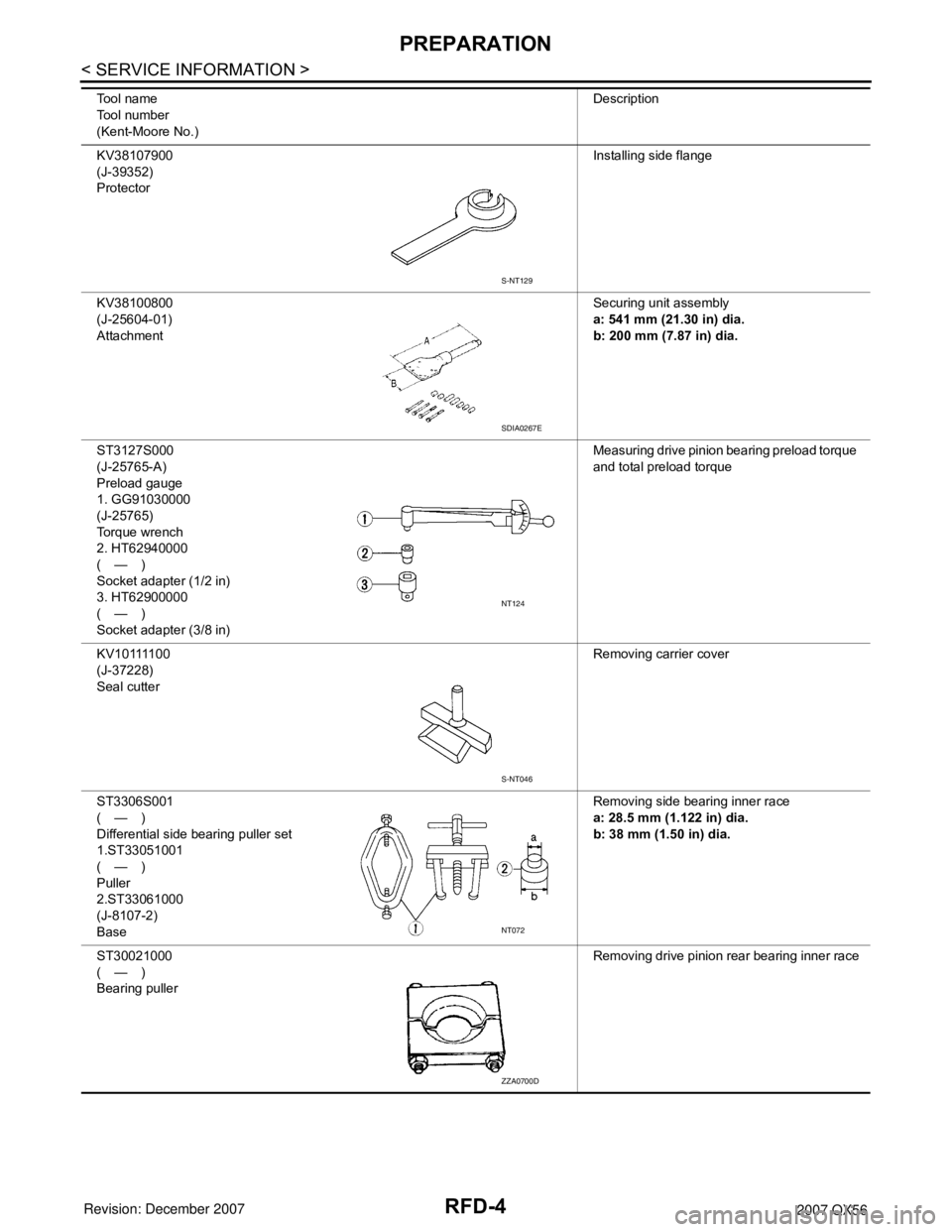
KV38107900
(J-39352)
ProtectorInstalling side flange
KV38100800
(J-25604-01)
AttachmentSecuring unit assembly
a: 541 mm (21.30 in) dia.
b: 200 mm (7.87 in) dia.
ST3127S000
(J-25765-A)
Preload gauge
1. GG91030000
(J-25765)
Torque wrench
2. HT62940000
(—)
Socket adapter (1/2 in)
3. HT62900000
(—)
Socket adapter (3/8 in)Measuring drive pinion bearing preload torque
and total preload torque
K V 1 0 1111 0 0
(J-37228)
Seal cutterRemoving carrier cover
ST3306S001
(—)
Differential side bearing puller set
1.ST33051001
(—)
Puller
2.ST33061000
(J-8107-2)
BaseRemoving side bearing inner race
a: 28.5 mm (1.122 in) dia.
b: 38 mm (1.50 in) dia.
ST30021000
(—)
Bearing pullerRemoving drive pinion rear bearing inner race Tool name
Tool number
(Kent-Moore No.)Description
S-NT129
SDIA0267E
NT124
S-NT046
NT072
ZZA0700D
Page 2572 of 3061
REAR FINAL DRIVE ASSEMBLY
RFD-15
< SERVICE INFORMATION >
C
E
F
G
H
I
J
K
L
MA
B
RFD
N
O
P
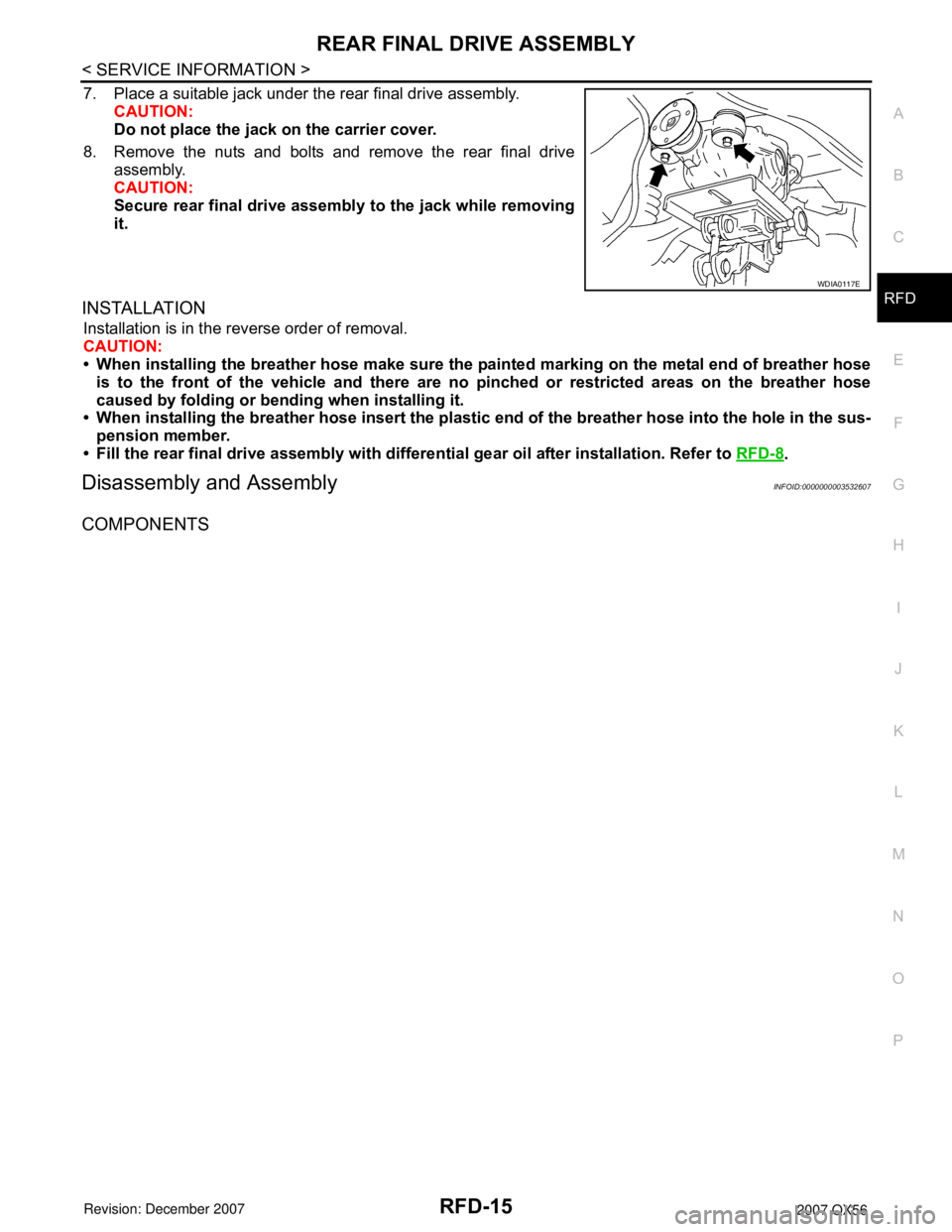
7. Place a suitable jack under the rear final drive assembly.
CAUTION:
Do not place the jack on the carrier cover.
8. Remove the nuts and bolts and remove the rear final drive
assembly.
CAUTION:
Secure rear final drive assembly to the jack while removing
it.
INSTALLATION
Installation is in the reverse order of removal.
CAUTION:
• When installing the breather hose make sure the painted marking on the metal end of breather hose
is to the front of the vehicle and there are no pinched or restricted areas on the breather hose
caused by folding or bending when installing it.
• When installing the breather hose insert the plastic end of the breather hose into the hole in the sus-
pension member.
• Fill the rear final drive assembly with differential gear oil after installation. Refer to RFD-8
.
Disassembly and AssemblyINFOID:0000000003532607
COMPONENTS
WDIA0117E
Page 2601 of 3061
TROUBLE DIAGNOSIS
RSU-11
< SERVICE INFORMATION >
C
D
F
G
H
I
J
K
L
MA
B
RSU
N
O
P
POWER SYSTEM TERMINAL LOOSENESS AND BATTERY INSPECTION
Make sure the battery positive cable, negative cable and ground connection are not loose. In addition, make
sure the battery is sufficiently charged.
CK SUSP INDICATOR LAMP INSPECTION
1. Make sure the CK SUSP indicator lamp turns on for approximately 2 seconds when the ignition switch is
turned ON. If it does not, check the combination meter. Refer to DI-5
.
2. Make sure the lamp turns off approximately 2 seconds after the ignition switch is turned ON. If the lamp
does not turn off, conduct self-diagnosis of the suspension control unit.
3. After conducting the self-diagnosis, be sure to erase the error memory. Refer to RSU-11, "
CONSULT-II
Function (AIR LEVELIZER)" .
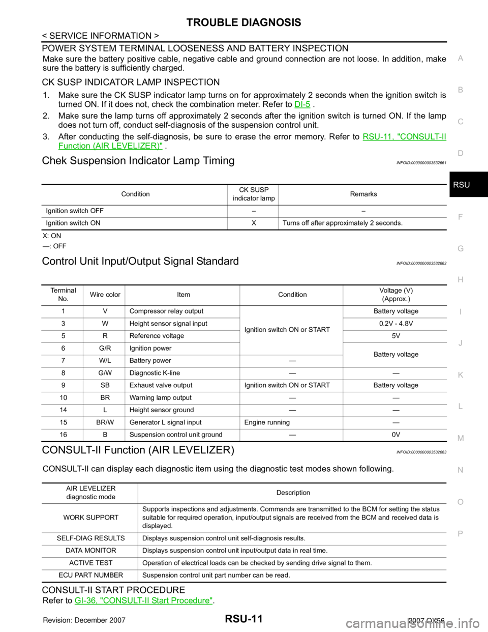
Chek Suspension Indicator Lamp TimingINFOID:0000000003532661
X: ON
—: OFF
Control Unit Input/Output Signal StandardINFOID:0000000003532662
CONSULT-II Function (AIR LEVELIZER)INFOID:0000000003532663
CONSULT-II can display each diagnostic item using the diagnostic test modes shown following.
CONSULT-II START PROCEDURE
Refer to GI-36, "CONSULT-II Start Procedure".
ConditionCK SUSP
indicator lampRemarks
Ignition switch OFF – –
Ignition switch ON X Turns off after approximately 2 seconds.
Te r m i n a l
No.Wire color Item ConditionVoltage (V)
(Approx.)
1 V Compressor relay output
Ignition switch ON or STARTBattery voltage
3 W Height sensor signal input 0.2V - 4.8V
5 R Reference voltage 5V
6 G/R Ignition power
Battery voltage
7W/LBattery power —
8 G/W Diagnostic K-line — —
9 SB Exhaust valve output Ignition switch ON or START Battery voltage
10 BR Warning lamp output — —
14 L Height sensor ground — —
15 BR/W Generator L signal input Engine running —
16 B Suspension control unit ground — 0V
AIR LEVELIZER
diagnostic modeDescription
WORK SUPPORTSupports inspections and adjustments. Commands are transmitted to the BCM for setting the status
suitable for required operation, input/output signals are received from the BCM and received data is
displayed.
SELF-DIAG RESULTS Displays suspension control unit self-diagnosis results.
DATA MONITOR Displays suspension control unit input/output data in real time.
ACTIVE TEST Operation of electrical loads can be checked by sending drive signal to them.
ECU PART NUMBER Suspension control unit part number can be read.
Page 2619 of 3061
REAR SUSPENSION MEMBER
RSU-29
< SERVICE INFORMATION >
C
D
F
G
H
I
J
K
L
MA
B
RSU
N
O
P
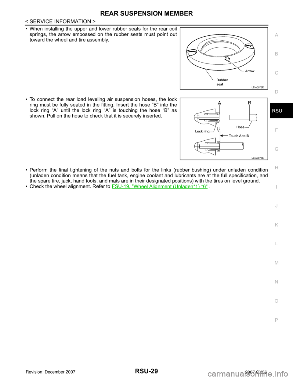
• When installing the upper and lower rubber seats for the rear coil
springs, the arrow embossed on the rubber seats must point out
toward the wheel and tire assembly.
• To connect the rear load leveling air suspension hoses, the lock
ring must be fully seated in the fitting. Insert the hose “B” into the
lock ring “A” until the lock ring “A” is touching the hose “B” as
shown. Pull on the hose to check that it is securely inserted.
• Perform the final tightening of the nuts and bolts for the links (rubber bushing) under unladen condition
(unladen condition means that the fuel tank, engine coolant and lubricants are at the full specification, and
the spare tire, jack, hand tools, and mats are in their designated positions) with the tires on level ground.
• Check the wheel alignment. Refer to FSU-19, "
Wheel Alignment (Unladen*1) *6" .
LEIA0076E
LEIA0078E
Page 2629 of 3061
REAR LOAD LEVELING AIR SUSPENSION COMPRESSOR ASSEMBLY
RSU-39
< SERVICE INFORMATION >
C
D
F
G
H
I
J
K
L
MA
B
RSU
N
O
P
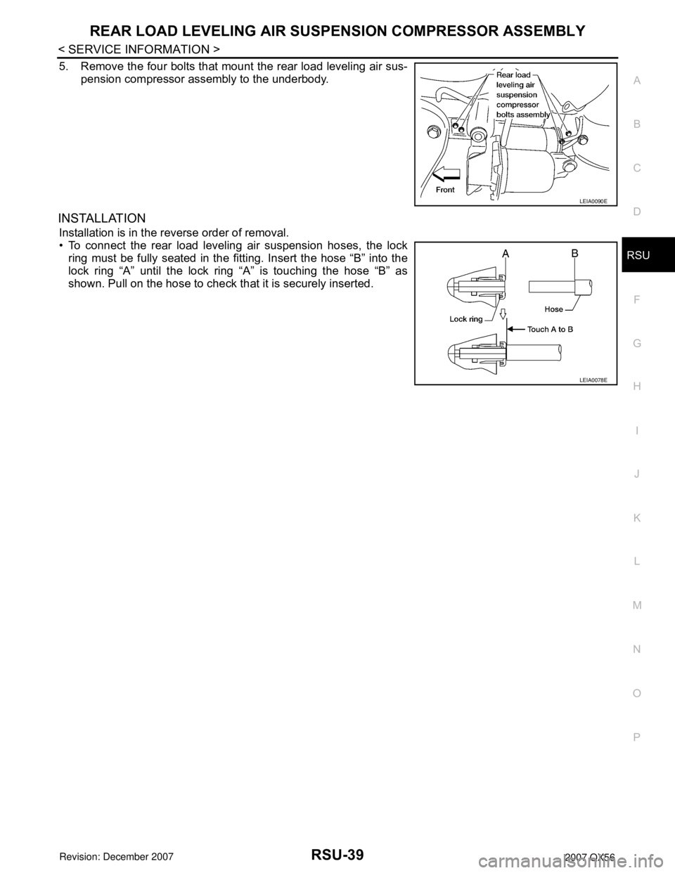
5. Remove the four bolts that mount the rear load leveling air sus-
pension compressor assembly to the underbody.
INSTALLATION
Installation is in the reverse order of removal.
• To connect the rear load leveling air suspension hoses, the lock
ring must be fully seated in the fitting. Insert the hose “B” into the
lock ring “A” until the lock ring “A” is touching the hose “B” as
shown. Pull on the hose to check that it is securely inserted.
LEIA0090E
LEIA0078E
Page 2644 of 3061
SB-10
< SERVICE INFORMATION >
SEAT BELTS
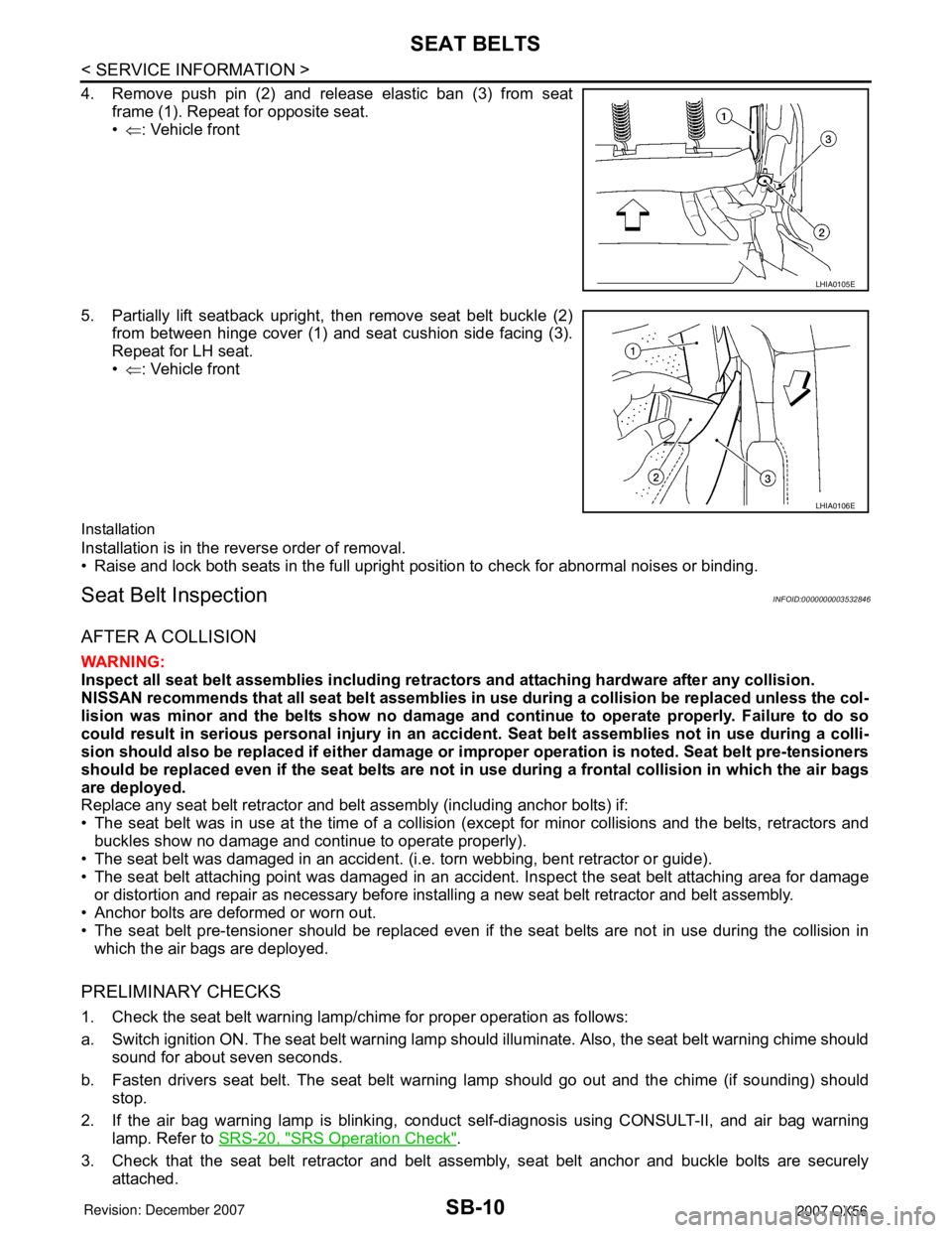
4. Remove push pin (2) and release elastic ban (3) from seat
frame (1). Repeat for opposite seat.
•⇐: Vehicle front
5. Partially lift seatback upright, then remove seat belt buckle (2)
from between hinge cover (1) and seat cushion side facing (3).
Repeat for LH seat.
•⇐: Vehicle front
Installation
Installation is in the reverse order of removal.
• Raise and lock both seats in the full upright position to check for abnormal noises or binding.
Seat Belt InspectionINFOID:0000000003532846
AFTER A COLLISION
WARNING:
Inspect all seat belt assemblies including retractors and attaching hardware after any collision.
NISSAN recommends that all seat belt assemblies in use during a collision be replaced unless the col-
lision was minor and the belts show no damage and continue to operate properly. Failure to do so
could result in serious personal injury in an accident. Seat belt assemblies not in use during a colli-
sion should also be replaced if either damage or improper operation is noted. Seat belt pre-tensioners
should be replaced even if the seat belts are not in use during a frontal collision in which the air bags
are deployed.
Replace any seat belt retractor and belt assembly (including anchor bolts) if:
• The seat belt was in use at the time of a collision (except for minor collisions and the belts, retractors and
buckles show no damage and continue to operate properly).
• The seat belt was damaged in an accident. (i.e. torn webbing, bent retractor or guide).
• The seat belt attaching point was damaged in an accident. Inspect the seat belt attaching area for damage
or distortion and repair as necessary before installing a new seat belt retractor and belt assembly.
• Anchor bolts are deformed or worn out.
• The seat belt pre-tensioner should be replaced even if the seat belts are not in use during the collision in
which the air bags are deployed.
PRELIMINARY CHECKS
1. Check the seat belt warning lamp/chime for proper operation as follows:
a. Switch ignition ON. The seat belt warning lamp should illuminate. Also, the seat belt warning chime should
sound for about seven seconds.
b. Fasten drivers seat belt. The seat belt warning lamp should go out and the chime (if sounding) should
stop.
2. If the air bag warning lamp is blinking, conduct self-diagnosis using CONSULT-II, and air bag warning
lamp. Refer to SRS-20, "
SRS Operation Check".
3. Check that the seat belt retractor and belt assembly, seat belt anchor and buckle bolts are securely
attached.
LHIA0105E
LHIA0106E
Page 2645 of 3061
SEAT BELTS
SB-11
< SERVICE INFORMATION >
C
D
E
F
G
I
J
K
L
MA
B
SB
N
O
P
4. Check the shoulder seat belt guide and shoulder belt height adjuster for front seats. Ensure guide swivels
freely and that belt lays flat and does not bind in guide. Ensure height adjuster operates properly and
holds securely.
5. Check retractor operation:
a. Fully extend the seat belt webbing and check for twists, tears or other damage.
b. Allow the seat belt to retract. Ensure that belt returns smoothly and completely into the retractor. If the
seat belt does not return smoothly, wipe the inside of the loops with a clean paper cloth, because dirt built
up in the loops of the upper anchors can cause the seat belts to retract slowly.
c. Fasten the seat belt. Check the seat belt returns smoothly and completely to the retractor. If the belt does
not return smoothly, the cause may be an accumulation of dust or dirt. Use the “SEAT BELT TAPE SET”
and perform the following steps.
Inspect the front seat belt through-anchor:1. Pull the seat belt out to a length of 500 mm (19.69 in) or more.
2. Use a clip or other device to hold the seat belt at the center pillar belt opening.
3. Pass a thin wire through the through-anchor belt opening. Hold both ends of the wire and pull taut
while moving it up and down several times along the belt opening surface to remove dirt.
4. Any dirt that cannot be removed with the wire can be removed by cleaning the opening with a clean
cloth.
5. Apply tape at the point where the belt contacts the through-anchor belt opening.
NOTE:
Apply the tape so that there is no looseness or wrinkling.
6. Remove the clip holding the seat belt and check that the belt returns smoothly.
7. Repeat steps above as necessary to check the other seat belts.
SEAT BELT RETRACTOR ON-VEHICLE CHECK
Emergency Locking Retractors (ELR) and Automatic Locking Retractors (ALR)
NOTE:
All seat belt retractors are of the Emergency Locking Retractors (ELR) type. In an emergency (sudden stop)
the retractor will lock and prevent the belt from extending any further. All 3-point type seat belt retractors
except the driver's seat belt also have an Automatic Locking Retractors (ALR) mode. The ALR mode (also
called child restraint mode) is used when installing child seats. The ALR mode is activated when the seat belt
is fully extended. When the belt is then retracted partially, the ALR mode automatically locks the seat belt in a
specific position so the belt cannot be extended any further. To cancel the ALR mode, allow the seat belt to
fully wind back into the retractor.
Check the seat belt retractors using the following test(s) to determine if a seat belt retractor and belt assembly
is operating properly.
ELR Function Stationary Check
Grasp the shoulder belt and pull forward quickly. The retractor should lock and prevent the belt from extending
further.
ALR Function Stationary Check
1. Pull out entire length of seat belt from retractor until a click is heard.
2. Retract the belt partially. A clicking noise should be heard as the belt retracts indicating that the retractor is
in the Automatic Locking Retractor (ALR) mode.
3. Grasp the seat belt and try to pull out the retractor. The belt must lock and not extend any further. If neces-
sary replace the seat belt retractor and belt assembly.
4. Allow the entire length of the belt to retract to cancel the automatic locking mode.
ELR Function Moving Check
WARNING:
Perform the following test in a safe, open area clear of other vehicles and obstructions (for example, a
large, empty parking lot). Road surface must be paved and dry. DO NOT perform the following test on
wet or gravel roads or on public streets and highways. This could result in an accident and serious
personal injury. The driver and passenger must be prepared to brace themselves in the event the
retractor does not lock.
1. Fasten drivers seat belt. Buckle a passenger into the seat for the belt that is to be tested.