2007 INFINITI QX56 air condition
[x] Cancel search: air conditionPage 1031 of 3061
DI-20
< SERVICE INFORMATION >
COMBINATION METERS
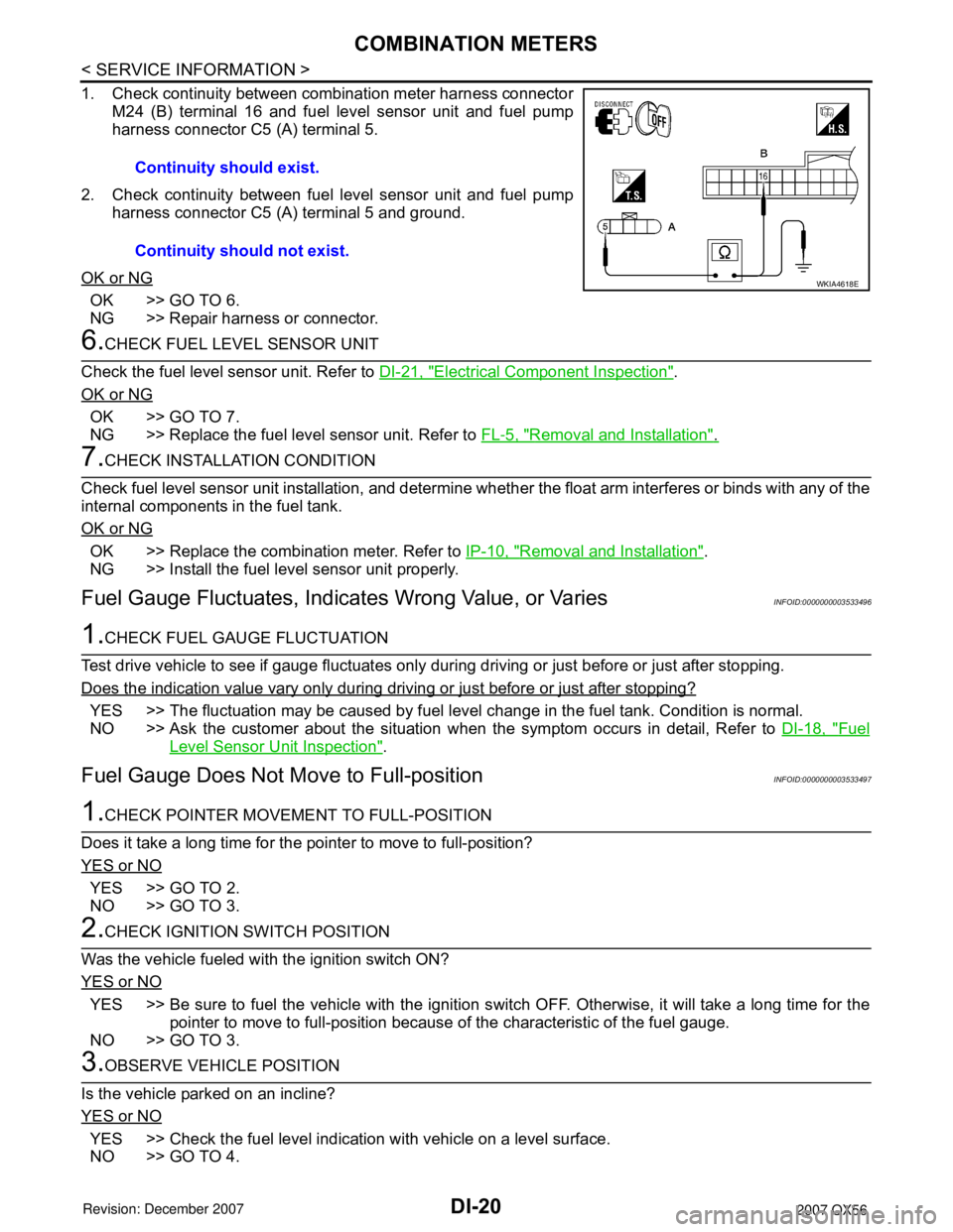
1. Check continuity between combination meter harness connectorM24 (B) terminal 16 and fuel level sensor unit and fuel pump
harness connector C5 (A) terminal 5.
2. Check continuity between fuel level sensor unit and fuel pump harness connector C5 (A) terminal 5 and ground.
OK or NG
OK >> GO TO 6.
NG >> Repair harness or connector.
6.CHECK FUEL LEVEL SENSOR UNIT
Check the fuel level sensor unit. Refer to DI-21, "
Electrical Component Inspection".
OK or NG
OK >> GO TO 7.
NG >> Replace the fuel level sensor unit. Refer to FL-5, "
Removal and Installation".
7.CHECK INSTALLATION CONDITION
Check fuel level sensor unit installation, and determine whet her the float arm interferes or binds with any of the
internal components in the fuel tank.
OK or NG
OK >> Replace the combination meter. Refer to IP-10, "Removal and Installation".
NG >> Install the fuel level sensor unit properly.
Fuel Gauge Fluctuat es, Indicates Wrong Value, or VariesINFOID:0000000003533496
1.CHECK FUEL GAUGE FLUCTUATION
Test drive vehicle to see if gauge fluctuates only during driving or just before or just after stopping.
Does the indication value vary only during driving or just before or just after stopping?
YES >> The fluctuation may be caused by fuel leve l change in the fuel tank. Condition is normal.
NO >> Ask the customer about the situation when the symptom occurs in detail, Refer to DI-18, "
Fuel
Level Sensor Unit Inspection".
Fuel Gauge Does Not Move to Full-positionINFOID:0000000003533497
1.CHECK POINTER MOVEME NT TO FULL-POSITION
Does it take a long time for the pointer to move to full-position?
YES or NO
YES >> GO TO 2.
NO >> GO TO 3.
2.CHECK IGNITION SWITCH POSITION
Was the vehicle fueled with the ignition switch ON?
YES or NO
YES >> Be sure to fuel the vehicle with the ignition s witch OFF. Otherwise, it will take a long time for the
pointer to move to full-position because of the characteristic of the fuel gauge.
NO >> GO TO 3.
3.OBSERVE VEHICLE POSITION
Is the vehicle parked on an incline?
YES or NO
YES >> Check the fuel level indication with vehicle on a level surface.
NO >> GO TO 4. Continuity should exist.
Continuity should not exist.
WKIA4618E
Page 1051 of 3061
DI-40
< SERVICE INFORMATION >
WARNING CHIME
How to Proceed with Trouble Diagnosis
INFOID:0000000003533516
1. Confirm the symptom or customer complaint.
2. Understand operation description and function description. Refer to DI-36, "
System Description".
3. Perform the preliminary check. Refer to DI-40, "
Preliminary Check".
4. Check symptom and repair or replace the cause of malfunction.
5. Does the warning chime operate properly? If so, go to 6. If not, go to 3.
6. Inspection End.
Preliminary CheckINFOID:0000000003533517
INSPECTION FOR POWER SUPPLY AND GROUND CIRCUIT
Refer to BCS-15, "BCM Power Supply and Ground Circuit Inspection".
CONSULT-II Function (BCM)INFOID:0000000003533518
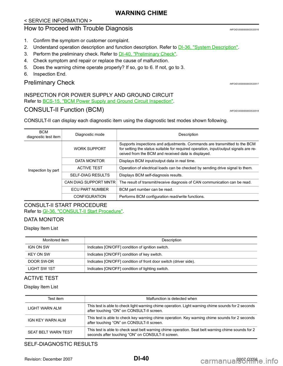
CONSULT-II can display each diagnostic item using the diagnostic test modes shown following.
CONSULT-II START PROCEDURE
Refer to GI-36, "CONSULT-II Start Procedure".
DATA MONITOR
Display Item List
ACTIVE TEST
Display Item List
SELF-DIAGNOSTIC RESULTS
BCM
diagnostic test itemDiagnostic mode Description
Inspection by partWORK SUPPORTSupports inspections and adjustments. Commands are transmitted to the BCM
for setting the status suitable for required operation, input/output signals are re-
ceived from the BCM and received data is displayed.
DATA MONITOR Displays BCM input/output data in real time.
ACTIVE TEST Operation of electrical loads can be checked by sending drive signal to them.
SELF-DIAG RESULTS Displays BCM self-diagnosis results.
CAN DIAG SUPPORT MNTR The result of transmit/receive diagnosis of CAN communication can be read.
ECU PART NUMBER BCM part number can be read.
CONFIGURATION Performs BCM configuration read/write functions.
Monitored item Description
IGN ON SW Indicates [ON/OFF] condition of ignition switch.
KEY ON SW Indicates [ON/OFF] condition of key switch.
DOOR SW-DR Indicates [ON/OFF] condition of front door switch (driver side).
LIGHT SW 1ST Indicates [ON/OFF] condition of lighting switch.
Test item Malfunction is detected when
LIGHT WARN ALMThis test is able to check light warning chime operation. Light warning chime sounds for 2 seconds
after touching “ON” on CONSULT-II screen.
IGN KEY WARN ALMThis test is able to check key warning chime operation. Key warning chime sounds for 2 seconds
after touching “ON” on CONSULT-II screen.
SEAT BELT WARN TESTThis test is able to check seat belt warning chime operation. Seat belt warning chime sounds for 2
seconds after touching “ON” on CONSULT-II screen.
Page 1054 of 3061
WARNING CHIME
DI-43
< SERVICE INFORMATION >
C
D
E
F
G
H
I
J
L
MA
B
DI
N
O
P
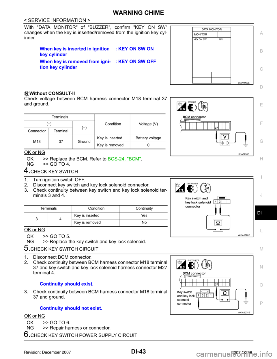
With "DATA MONITOR" of "BUZZER", confirm "KEY ON SW"
changes when the key is inserted/removed from the ignition key cyl-
inder.
Without CONSULT-II
Check voltage between BCM harness connector M18 terminal 37
and ground.
OK or NG
OK >> Replace the BCM. Refer to BCS-24, "BCM".
NG >> GO TO 4.
4.CHECK KEY SWITCH
1. Turn ignition switch OFF.
2. Disconnect key switch and key lock solenoid connector.
3. Check continuity between key switch and key lock solenoid ter-
minals 3 and 4.
OK or NG
OK >> GO TO 5.
NG >> Replace the key switch and key lock solenoid.
5.CHECK KEY SWITCH CIRCUIT
1. Disconnect BCM connector.
2. Check continuity between BCM harness connector M18 terminal
37 and key switch and key lock solenoid harness connector M27
terminal 4.
3. Check continuity between BCM harness connector M18 terminal
37 and ground.
OK or NG
OK >> GO TO 6.
NG >> Repair harness or connector.
6.CHECK KEY SWITCH POWER SUPPLY CIRCUITWhen key is inserted in ignition
key cylinder: KEY ON SW ON
When key is removed from igni-
tion key cylinder: KEY ON SW OFF
SKIA1960E
Te r m i n a l s
Condition Voltage (V) (+)
(–)
Connector Terminal
M18 37 GroundKey is insertedBattery voltage
Key is removed 0
LKIA0255E
Terminals Condition Continuity
34Key is inserted Yes
Key is removed No
WKIA1820E
Continuity should exist.
Continuity should not exist.
WKIA2074E
Page 1056 of 3061
WARNING CHIME
DI-45
< SERVICE INFORMATION >
C
D
E
F
G
H
I
J
L
MA
B
DI
N
O
P
3.CHECK COMBINATION METER INPUT SIGNAL
1. Turn ignition switch ON.
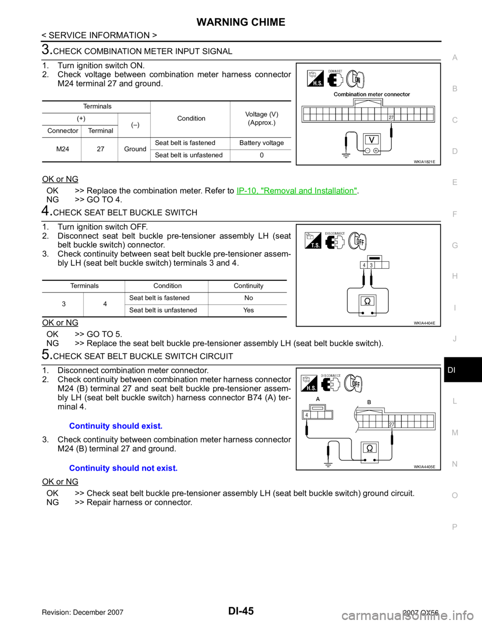
2. Check voltage between combination meter harness connector
M24 terminal 27 and ground.
OK or NG
OK >> Replace the combination meter. Refer to IP-10, "Removal and Installation".
NG >> GO TO 4.
4.CHECK SEAT BELT BUCKLE SWITCH
1. Turn ignition switch OFF.
2. Disconnect seat belt buckle pre-tensioner assembly LH (seat
belt buckle switch) connector.
3. Check continuity between seat belt buckle pre-tensioner assem-
bly LH (seat belt buckle switch) terminals 3 and 4.
OK or NG
OK >> GO TO 5.
NG >> Replace the seat belt buckle pre-tensioner assembly LH (seat belt buckle switch).
5.CHECK SEAT BELT BUCKLE SWITCH CIRCUIT
1. Disconnect combination meter connector.
2. Check continuity between combination meter harness connector
M24 (B) terminal 27 and seat belt buckle pre-tensioner assem-
bly LH (seat belt buckle switch) harness connector B74 (A) ter-
minal 4.
3. Check continuity between combination meter harness connector
M24 (B) terminal 27 and ground.
OK or NG
OK >> Check seat belt buckle pre-tensioner assembly LH (seat belt buckle switch) ground circuit.
NG >> Repair harness or connector.
Te r m i n a l s
ConditionVoltage (V)
(Approx.) (+)
(–)
Connector Terminal
M24 27 GroundSeat belt is fastened Battery voltage
Seat belt is unfastened 0
WKIA1821E
Terminals Condition Continuity
34Seat belt is fastened No
Seat belt is unfastened Yes
WKIA4404E
Continuity should exist.
Continuity should not exist.
WKIA4405E
Page 1065 of 3061
DI-54
< SERVICE INFORMATION >
REAR SONAR SYSTEM
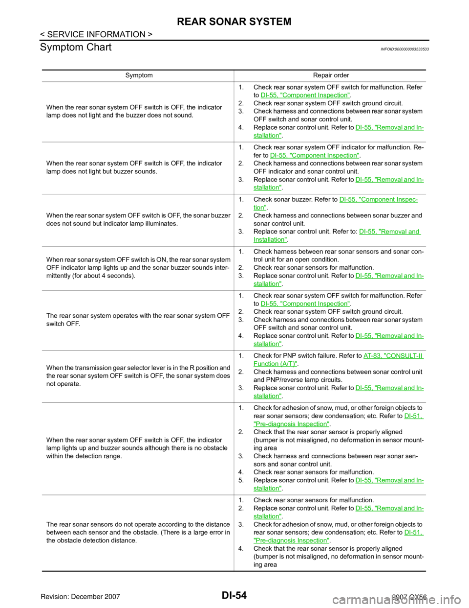
Symptom Chart
INFOID:0000000003533533
Symptom Repair order
When the rear sonar system OFF switch is OFF, the indicator
lamp does not light and the buzzer does not sound.1. Check rear sonar system OFF switch for malfunction. Refer
to DI-55, "
Component Inspection".
2. Check rear sonar system OFF switch ground circuit.
3. Check harness and connections between rear sonar system
OFF switch and sonar control unit.
4. Replace sonar control unit. Refer to DI-55, "
Removal and In-
stallation".
When the rear sonar system OFF switch is OFF, the indicator
lamp does not light but buzzer sounds.1. Check rear sonar system OFF indicator for malfunction. Re-
fer to DI-55, "
Component Inspection".
2. Check harness and connections between rear sonar system
OFF indicator and sonar control unit.
3. Replace sonar control unit. Refer to DI-55, "
Removal and In-
stallation".
When the rear sonar system OFF switch is OFF, the sonar buzzer
does not sound but indicator lamp illuminates.1. Check sonar buzzer. Refer to DI-55, "
Component Inspec-
tion".
2. Check harness and connections between sonar buzzer and
sonar control unit.
3. Replace sonar control unit. Refer to: DI-55, "
Removal and
Installation".
When rear sonar system OFF switch is ON, the rear sonar system
OFF indicator lamp lights up and the sonar buzzer sounds inter-
mittently (for about 4 seconds).1. Check harness between rear sonar sensors and sonar con-
trol unit for an open condition.
2. Check rear sonar sensors for malfunction.
3. Replace sonar control unit. Refer to DI-55, "
Removal and In-
stallation".
The rear sonar system operates with the rear sonar system OFF
switch OFF.1. Check rear sonar system OFF switch for malfunction. Refer
to DI-55, "
Component Inspection".
2. Check rear sonar system OFF switch ground circuit.
3. Check harness and connections between rear sonar system
OFF switch and sonar control unit.
4. Replace sonar control unit. Refer to DI-55, "
Removal and In-
stallation".
When the transmission gear selector lever is in the R position and
the rear sonar system OFF switch is OFF, the sonar system does
not operate.1. Check for PNP switch failure. Refer to AT- 8 3 , "
CONSULT-II
Function (A/T)".
2. Check harness and connections between sonar control unit
and PNP/reverse lamp circuits.
3. Replace sonar control unit. Refer to DI-55, "
Removal and In-
stallation".
When the rear sonar system OFF switch is OFF, the indicator
lamp lights up and buzzer sounds although there is no obstacle
within the detection range.1. Check for adhesion of snow, mud, or other foreign objects to
rear sonar sensors; dew condensation; etc. Refer to DI-51,
"Pre-diagnosis Inspection".
2. Check that the rear sonar sensor is properly aligned
(bumper is not misaligned, no deformation in sensor mount-
ing area
3. Check harness and connections between rear sonar sen-
sors and sonar control unit.
4. Check rear sonar sensors for malfunction.
5. Replace sonar control unit. Refer to DI-55, "
Removal and In-
stallation".
The rear sonar sensors do not operate according to the distance
between each sensor and the obstacle. (There is a large error in
the obstacle detection distance.1. Check rear sonar sensors for malfunction.
2. Replace sonar control unit. Refer to DI-55, "
Removal and In-
stallation".
3. Check for adhesion of snow, mud, or other foreign objects to
rear sonar sensors; dew condensation; etc. Refer to DI-51,
"Pre-diagnosis Inspection".
4. Check that the rear sonar sensor is properly aligned
(bumper is not misaligned, no deformation in sensor mount-
ing area
Page 1084 of 3061

EC-1
ENGINE
C
D
E
F
G
H
I
J
K
L
M
SECTION EC
A
EC
N
O
P
CONTENTS
ENGINE CONTROL SYSTEM
SERVICE INFORMATION ............................9
INDEX FOR DTC .................................................9
DTC No. Index ..........................................................9
Alphabetical Index ...................................................12
PRECAUTIONS ..................................................17
Precaution for Supplemental Restraint System
(SRS) "AIR BAG" and "SEAT BELT PRE-TEN-
SIONER" .................................................................
17
On Board Diagnosis (OBD) System of Engine and
A/T ...........................................................................
17
Precaution ...............................................................17
PREPARATION ..................................................21
Special Service Tool ...............................................21
Commercial Service Tool ........................................22
ENGINE CONTROL SYSTEM ............................24
Schematic ...............................................................24
Multiport Fuel Injection (MFI) System .....................24
Electronic Ignition (EI) System ................................27
Fuel Cut Control (at No Load and High Engine
Speed) .....................................................................
27
AIR CONDITIONING CUT CONTROL ...............29
Input/Output Signal Chart ........................................29
System Description .................................................29
AUTOMATIC SPEED CONTROL DEVICE
(ASCD) ...............................................................
30
System Description .................................................30
Component Description ...........................................31
CAN COMMUNICATION ....................................32
System Description .................................................32
EVAPORATIVE EMISSION SYSTEM ................33
Description ..............................................................33
Component Inspection ............................................35
Removal and Installation .........................................37
How to Detect Fuel Vapor Leakage ........................37
ON BOARD REFUELING VAPOR RECOV-
ERY (ORVR) ......................................................
40
System Description ..................................................40
Diagnosis Procedure ...............................................40
Component Inspection .............................................42
POSITIVE CRANKCASE VENTILATION .........45
Description ...............................................................45
Component Inspection .............................................45
IVIS (INFINITI VEHICLE IMMOBILIZER SYS-
TEM-NATS) .......................................................
47
Description ...............................................................47
ON BOARD DIAGNOSTIC (OBD) SYSTEM ....48
Introduction ..............................................................48
Two Trip Detection Logic .........................................48
Emission-related Diagnostic Information .................49
Malfunction Indicator Lamp (MIL) ............................63
OBD System Operation Chart .................................65
BASIC SERVICE PROCEDURE .......................71
Basic Inspection ......................................................71
Idle Speed and Ignition Timing Check .....................75
Procedure After Replacing ECM .............................77
VIN Registration ......................................................77
Accelerator Pedal Released Position Learning .......77
Throttle Valve Closed Position Learning .................77
Idle Air Volume Learning .........................................78
Fuel Pressure Check ...............................................80
TROUBLE DIAGNOSIS ....................................82
Trouble Diagnosis Introduction ................................82
DTC Inspection Priority Chart ..................................87
Fail-Safe Chart ........................................................88
Symptom Matrix Chart .............................................90
Engine Control Component Parts Location .............94
Vacuum Hose Drawing ..........................................100
Circuit Diagram ......................................................101
ECM Harness Connector Terminal Layout ............103
ECM Terminal and Reference Value .....................103
Page 1108 of 3061
ENGINE CONTROL SYSTEM
EC-25
< SERVICE INFORMATION >
C
D
E
F
G
H
I
J
K
L
MA
EC
N
P O
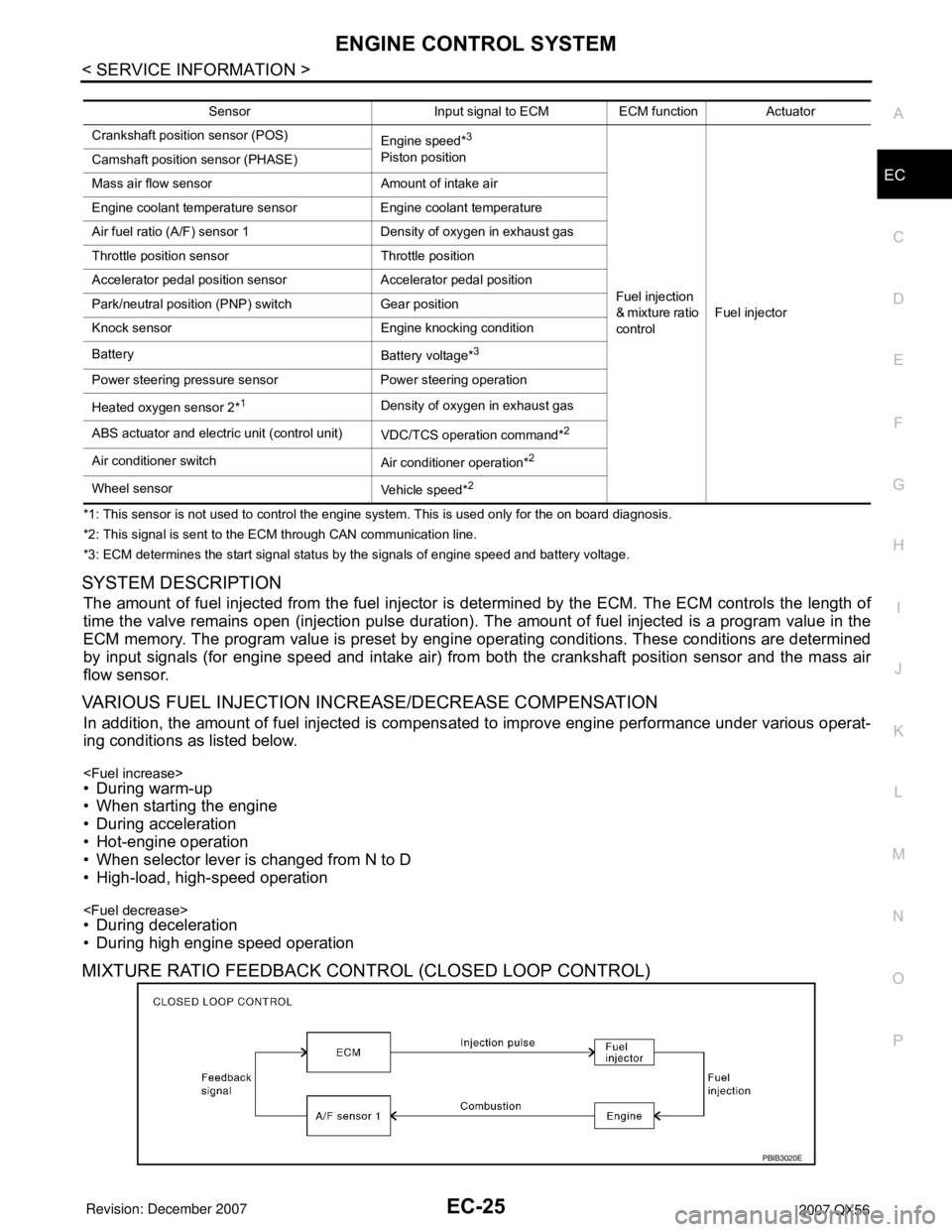
*1: This sensor is not used to control the engine system. This is used only for the on board diagnosis.
*2: This signal is sent to the ECM through CAN communication line.
*3: ECM determines the start signal status by the signals of engine speed and battery voltage.
SYSTEM DESCRIPTION
The amount of fuel injected from the fuel injector is determined by the ECM. The ECM controls the length of
time the valve remains open (injection pulse duration). The amount of fuel injected is a program value in the
ECM memory. The program value is preset by engine operating conditions. These conditions are determined
by input signals (for engine speed and intake air) from both the crankshaft position sensor and the mass air
flow sensor.
VARIOUS FUEL INJECTION INCREASE/DECREASE COMPENSATION
In addition, the amount of fuel injected is compensated to improve engine performance under various operat-
ing conditions as listed below.
• When starting the engine
• During acceleration
• Hot-engine operation
• When selector lever is changed from N to D
• High-load, high-speed operation
• During deceleration
• During high engine speed operation
MIXTURE RATIO FEEDBACK CONTROL (CLOSED LOOP CONTROL)
Sensor Input signal to ECM ECM function Actuator
Crankshaft position sensor (POS)
Engine speed*
3
Piston position
Fuel injection
& mixture ratio
controlFuel injector Camshaft position sensor (PHASE)
Mass air flow sensor Amount of intake air
Engine coolant temperature sensor Engine coolant temperature
Air fuel ratio (A/F) sensor 1 Density of oxygen in exhaust gas
Throttle position sensor Throttle position
Accelerator pedal position sensor Accelerator pedal position
Park/neutral position (PNP) switch Gear position
Knock sensor Engine knocking condition
Battery
Battery voltage*
3
Power steering pressure sensor Power steering operation
Heated oxygen sensor 2*
1Density of oxygen in exhaust gas
ABS actuator and electric unit (control unit)
VDC/TCS operation command*
2
Air conditioner switch
Air conditioner operation*2
Wheel sensor
Vehicle speed*2
PBIB3020E
Page 1109 of 3061
EC-26
< SERVICE INFORMATION >
ENGINE CONTROL SYSTEM
The mixture ratio feedback system provides the best air-fuel mixture ratio for driveability and emission control.
The three way catalyst (manifold) can then better reduce CO, HC and NOx emissions. This system uses air
fuel ratio (A/F) sensor 1 in the exhaust manifold to monitor whether the engine operation is rich or lean. The
ECM adjusts the injection pulse width according to the sensor voltage signal. For more information about air
fuel ratio (A/F) sensor 1, refer to EC-225
. This maintains the mixture ratio within the range of stoichiometric
(ideal air-fuel mixture).
This stage is referred to as the closed loop control condition.
Heated oxygen sensor 2 is located downstream of the three way catalyst (manifold). Even if the switching
characteristics of air fuel ratio (A/F) sensor 1 shift, the air-fuel ratio is controlled to stoichiometric by the signal
from heated oxygen sensor 2.
Open Loop Control
The open loop system condition refers to when the ECM detects any of the following conditions. Feedback
control stops in order to maintain stabilized fuel combustion.
• Deceleration and acceleration
• High-load, high-speed operation
• Malfunction of A/F sensor 1 or its circuit
• Insufficient activation of A/F sensor 1 at low engine coolant temperature
• High engine coolant temperature
• During warm-up
• After shifting from N to D
• When starting the engine
MIXTURE RATIO SELF-LEARNING CONTROL
The mixture ratio feedback control system monitors the mixture ratio signal transmitted from A/F sensor 1.
This feedback signal is then sent to the ECM. The ECM controls the basic mixture ratio as close to the theoret-
ical mixture ratio as possible. However, the basic mixture ratio is not necessarily controlled as originally
designed. Both manufacturing differences (i.e., mass air flow sensor hot wire) and characteristic changes dur-
ing operation (i.e., injector clogging) directly affect mixture ratio.
Accordingly, the difference between the basic and theoretical mixture ratios is monitored in this system. This is
then computed in terms of “injection pulse duration” to automatically compensate for the difference between
the two ratios.
“Fuel trim” refers to the feedback compensation value compared against the basic injection duration. Fuel trim
includes short term fuel trim and long term fuel trim.
“Short term fuel trim” is the short-term fuel compensation used to maintain the mixture ratio at its theoretical
value. The signal from A/F sensor 1 indicates whether the mixture ratio is RICH or LEAN compared to the the-
oretical value. The signal then triggers a reduction in fuel volume if the mixture ratio is rich, and an increase in
fuel volume if it is lean.
“Long term fuel trim” is overall fuel compensation carried out long-term to compensate for continual deviation
of the short term fuel trim from the central value. Such deviation will occur due to individual engine differences,
wear over time and changes in the usage environment.
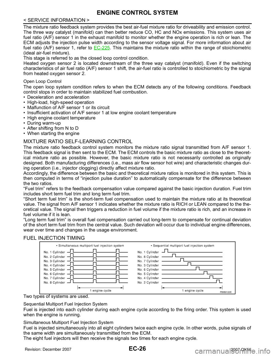
FUEL INJECTION TIMING
Two types of systems are used.
Sequential Multiport Fuel Injection System
Fuel is injected into each cylinder during each engine cycle according to the firing order. This system is used
when the engine is running.
Simultaneous Multiport Fuel Injection System
Fuel is injected simultaneously into all eight cylinders twice each engine cycle. In other words, pulse signals of
the same width are simultaneously transmitted from the ECM.
The eight fuel injectors will then receive the signals two times for each engine cycle.
PBIB0122E