Page 925 of 3061
REAR DISC BRAKE
BR-27
< SERVICE INFORMATION >
C
D
E
G
H
I
J
K
L
MA
B
BR
N
O
P
Make sure there is no wear, damage, or cracks in sliding sleeve and sliding sleeve boots, and if there are,
replace them.
ASSEMBLY
CAUTION:
Do not use NISSAN Rubber Grease (KRE00 00010, KRE00 00010 01) when assembling.
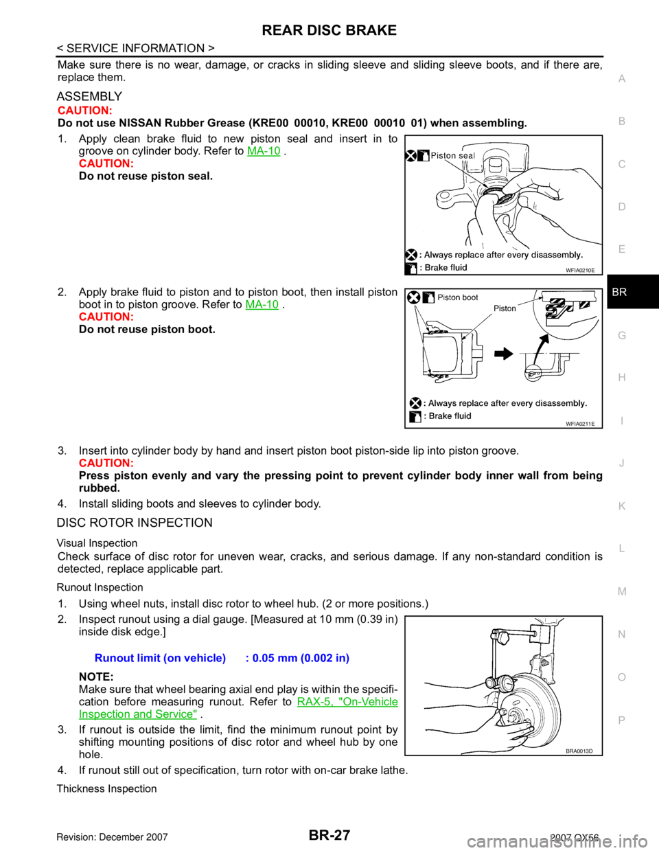
1. Apply clean brake fluid to new piston seal and insert in to
groove on cylinder body. Refer to MA-10
.
CAUTION:
Do not reuse piston seal.
2. Apply brake fluid to piston and to piston boot, then install piston
boot in to piston groove. Refer to MA-10
.
CAUTION:
Do not reuse piston boot.
3. Insert into cylinder body by hand and insert piston boot piston-side lip into piston groove.
CAUTION:
Press piston evenly and vary the pressing point to prevent cylinder body inner wall from being
rubbed.
4. Install sliding boots and sleeves to cylinder body.
DISC ROTOR INSPECTION
Visual Inspection
Check surface of disc rotor for uneven wear, cracks, and serious damage. If any non-standard condition is
detected, replace applicable part.
Runout Inspection
1. Using wheel nuts, install disc rotor to wheel hub. (2 or more positions.)
2. Inspect runout using a dial gauge. [Measured at 10 mm (0.39 in)
inside disk edge.]
NOTE:
Make sure that wheel bearing axial end play is within the specifi-
cation before measuring runout. Refer to RAX-5, "
On-Vehicle
Inspection and Service" .
3. If runout is outside the limit, find the minimum runout point by
shifting mounting positions of disc rotor and wheel hub by one
hole.
4. If runout still out of specification, turn rotor with on-car brake lathe.
Thickness Inspection
WFIA0210E
WFIA0211E
Runout limit (on vehicle) : 0.05 mm (0.002 in)
BRA0013D
Page 984 of 3061
![INFINITI QX56 2007 Factory Service Manual BRC-56
< SERVICE INFORMATION >[VDC/TCS/ABS]
WHEEL SENSOR
WHEEL SENSOR
Removal and InstallationINFOID:0000000003532811
REMOVAL
1. Remove wheel sensor bolt.
• When removing the front wheel sensor, fir INFINITI QX56 2007 Factory Service Manual BRC-56
< SERVICE INFORMATION >[VDC/TCS/ABS]
WHEEL SENSOR
WHEEL SENSOR
Removal and InstallationINFOID:0000000003532811
REMOVAL
1. Remove wheel sensor bolt.
• When removing the front wheel sensor, fir](/manual-img/42/57029/w960_57029-983.png)
BRC-56
< SERVICE INFORMATION >[VDC/TCS/ABS]
WHEEL SENSOR
WHEEL SENSOR
Removal and InstallationINFOID:0000000003532811
REMOVAL
1. Remove wheel sensor bolt.
• When removing the front wheel sensor, first remove the disc rotor to gain access to the front wheel sen-
sor bolt. Refer to BR-19, "
Removal and Installation of Brake Caliper and Disc Rotor" .
• When removing the rear wheel sensor, first remove the rear hub and bearing assembly to gain access to
the rear wheel sensor bolt. Refer to FA X - 5 , "
Removal and Installation" .
2. Pull out the sensor, being careful to turn it as little as possible.
CAUTION:
• Do not pull on the sensor harness.
3. Disconnect wheel sensor harness electrical connector, then remove harness from attaching points.
INSTALLATION
Installation is in the reverse order of removal. Tighten wheel sensor bolt to specification.
CAUTION:
Installation should be performed while paying attention to the following.
• Inspect wheel sensor O-ring, replace sensor assembly if damaged.
• Before installing wheel sensor, make sure no foreign materials (such as iron fragments) are adhered
to the pick-up part of the sensor, to the inside of the sensor hole or on the rotor mating surface.
• Apply a coat of suitable grease to the wheel sensor O-ring and hole. Refer to MA-10
.
WFIA0376E
Page 985 of 3061
SENSOR ROTOR
BRC-57
< SERVICE INFORMATION >[VDC/TCS/ABS]
C
D
E
G
H
I
J
K
L
MA
B
BRC
N
O
P
SENSOR ROTOR
Removal and InstallationINFOID:0000000003532812
NOTE:
The wheel sensor rotors are built into the wheel hubs and are not removable. If damaged, replace wheel hub
and bearing assembly. Refer to FAX-5, "
Removal and Installation" (front), RAX-5, "Removal and Installation"
(rear).
Page 2399 of 3061
PB-6
< SERVICE INFORMATION >
PARKING BRAKE SHOE
PARKING BRAKE SHOE
Removal and InstallationINFOID:0000000003532758
COMPONENTS
REMOVAL
WARNING:
Clean the brakes with a vacuum dust collector to minimize the hazard of airborne particles or other
materials.
NOTE:
Remove the disc rotor only with the parking brake pedal completely disengaged.
1. Remove wheel hub and bearing assembly. Refer to FA X - 5 , "
Removal and Installation" .
• Disconnect the wheel sensor at the harness connector. It is not necessary to remove the wheel sensor
from the wheel hub and bearing assembly.
2. Remove the return springs.
3. Remove the adjuster.
4. Remove the retainers, anti-rattle pins and shoes.
5. Disconnect the rear cable from the toggle lever.
6. Remove the back plate.
INSPECTION AFTER REMOVAL
Lining Thickness Inspection
1. Back plate 2. Shoes 3. Toggle lever
4. Return springs 5. Retainers 6. Adjuster
7. Anti-rattle pins
WFIA0164E
Page 2519 of 3061
RAX-1
DRIVELINE/AXLE
C
E
F
G
H
I
J
K
L
M
SECTION RAX
A
B
RAX
N
O
P
CONTENTS
REAR AXLE
SERVICE INFORMATION ............................2
PRECAUTIONS ...................................................2
Caution ......................................................................2
PREPARATION ...................................................3
Special Service Tool .................................................3
Commercial Service Tool ..........................................3
NOISE, VIBRATION AND HARSHNESS
(NVH) TROUBLESHOOTING .............................
4
NVH Troubleshooting Chart ......................................4
WHEEL HUB ......................................................5
On-Vehicle Inspection and Service ..........................5
Removal and Installation ..........................................5
REAR DRIVE SHAFT .........................................7
Component ...............................................................7
Removal and Installation ..........................................7
Disassembly and Assembly ......................................8
SERVICE DATA AND SPECIFICATIONS
(SDS) .................................................................
14
Wheel Bearing .........................................................14
Drive Shaft ...............................................................14
Page 2523 of 3061
WHEEL HUB
RAX-5
< SERVICE INFORMATION >
C
E
F
G
H
I
J
K
L
MA
B
RAX
N
O
P
WHEEL HUB
On-Vehicle Inspection and ServiceINFOID:0000000003532624
Inspect the components for any looseness or back lash. Inspect each component for any excessive wear or
damage. Replace any components as necessary.
WHEEL BEARING INSPECTION
• Move the wheel hub and bearing assembly in the axial direction by hand to check the axial end play. Check
that the axial end play is with specification. Replace the wheel hub and bearing assembly as necessary.
• Rotate the wheel hub and bearing assembly to check that there are no unusual noises or other abnormal
conditions. Replace the wheel hub and bearing assembly as necessary.
Removal and InstallationINFOID:0000000003532625
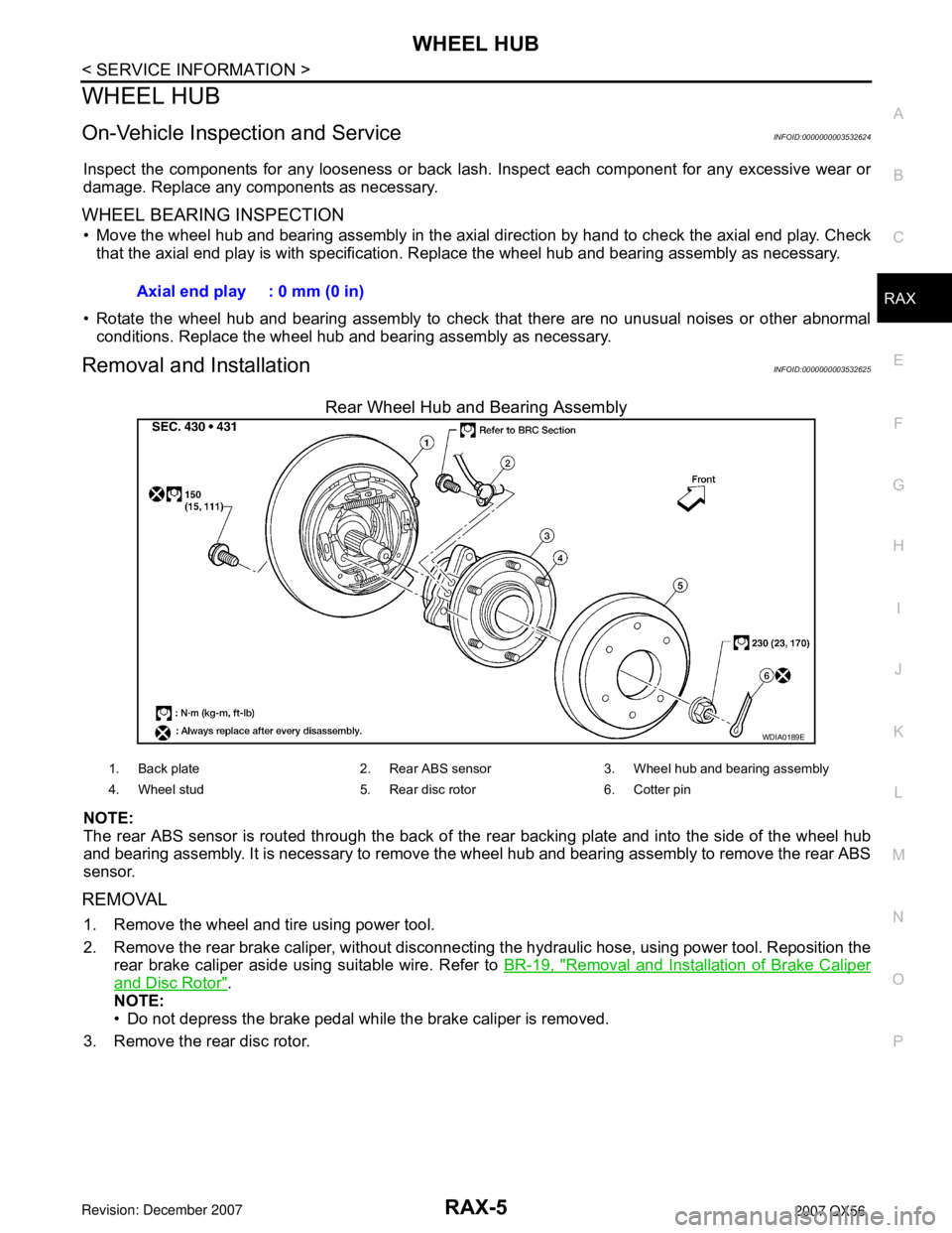
Rear Wheel Hub and Bearing Assembly
NOTE:
The rear ABS sensor is routed through the back of the rear backing plate and into the side of the wheel hub
and bearing assembly. It is necessary to remove the wheel hub and bearing assembly to remove the rear ABS
sensor.
REMOVAL
1. Remove the wheel and tire using power tool.
2. Remove the rear brake caliper, without disconnecting the hydraulic hose, using power tool. Reposition the
rear brake caliper aside using suitable wire. Refer to BR-19, "
Removal and Installation of Brake Caliper
and Disc Rotor".
NOTE:
• Do not depress the brake pedal while the brake caliper is removed.
3. Remove the rear disc rotor.Axial end play : 0 mm (0 in)
WDIA0189E
1. Back plate 2. Rear ABS sensor 3. Wheel hub and bearing assembly
4. Wheel stud 5. Rear disc rotor 6. Cotter pin
Page 2524 of 3061
RAX-6
< SERVICE INFORMATION >
WHEEL HUB
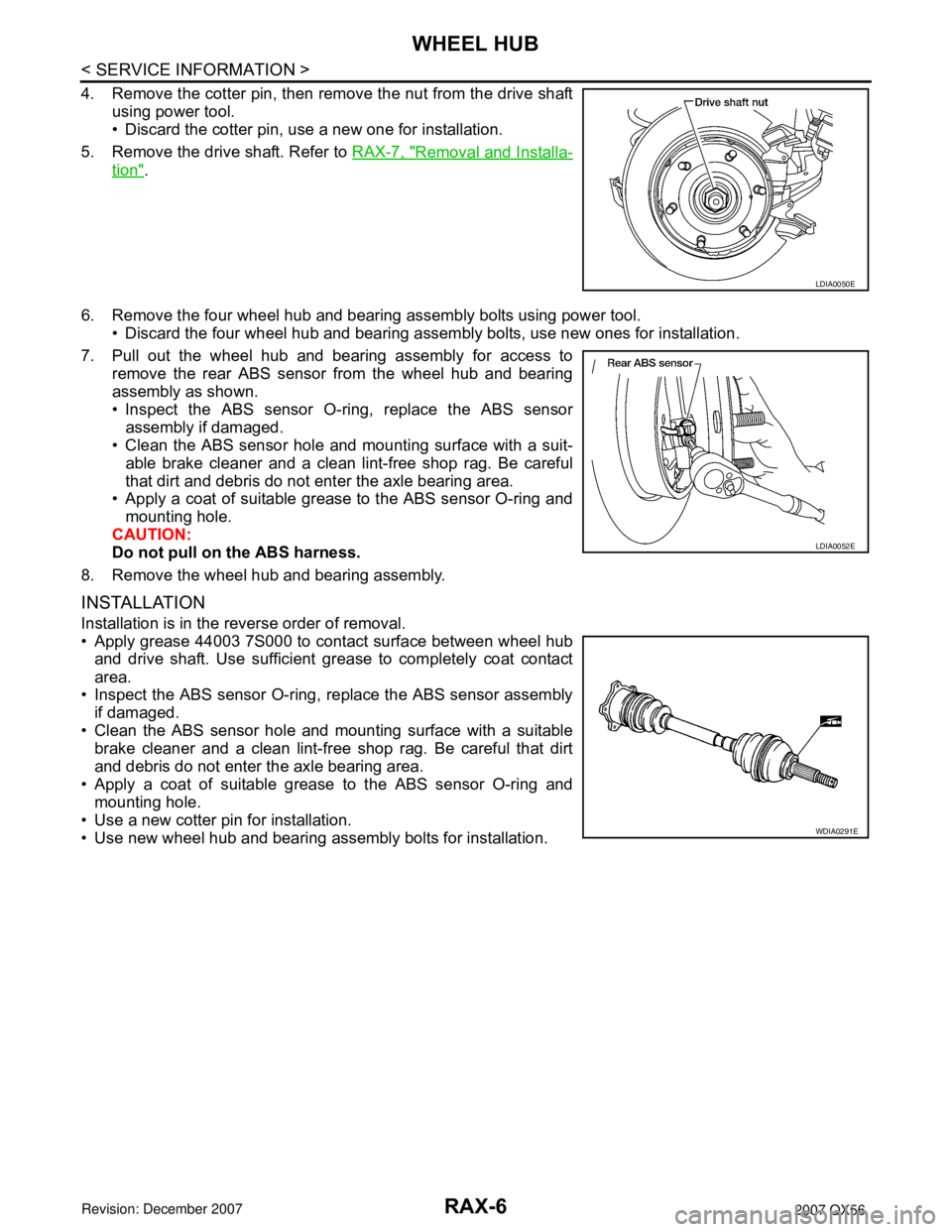
4. Remove the cotter pin, then remove the nut from the drive shaft
using power tool.
• Discard the cotter pin, use a new one for installation.
5. Remove the drive shaft. Refer to RAX-7, "
Removal and Installa-
tion".
6. Remove the four wheel hub and bearing assembly bolts using power tool.
• Discard the four wheel hub and bearing assembly bolts, use new ones for installation.
7. Pull out the wheel hub and bearing assembly for access to
remove the rear ABS sensor from the wheel hub and bearing
assembly as shown.
• Inspect the ABS sensor O-ring, replace the ABS sensor
assembly if damaged.
• Clean the ABS sensor hole and mounting surface with a suit-
able brake cleaner and a clean lint-free shop rag. Be careful
that dirt and debris do not enter the axle bearing area.
• Apply a coat of suitable grease to the ABS sensor O-ring and
mounting hole.
CAUTION:
Do not pull on the ABS harness.
8. Remove the wheel hub and bearing assembly.
INSTALLATION
Installation is in the reverse order of removal.
• Apply grease 44003 7S000 to contact surface between wheel hub
and drive shaft. Use sufficient grease to completely coat contact
area.
• Inspect the ABS sensor O-ring, replace the ABS sensor assembly
if damaged.
• Clean the ABS sensor hole and mounting surface with a suitable
brake cleaner and a clean lint-free shop rag. Be careful that dirt
and debris do not enter the axle bearing area.
• Apply a coat of suitable grease to the ABS sensor O-ring and
mounting hole.
• Use a new cotter pin for installation.
• Use new wheel hub and bearing assembly bolts for installation.
LDIA0050E
LDIA0052E
WDIA0291E
Page 2526 of 3061
RAX-8
< SERVICE INFORMATION >
REAR DRIVE SHAFT
5. Separate the drive shaft from the wheel hub and bearing assembly by lightly tapping the end with a suit-
able hammer and wood block. If it is difficult to separate, use a suitable puller.
6. Remove the drive shaft.
CAUTION:
When removing the drive shaft, do not bend at an excessive angle to the drive shaft joint. Do not
excessively extend the slide joint.
INSPECTION AFTER REMOVAL
• Move the joint up and down, left and right, and in the axial direc-
tion. Check for any rough movement or significant looseness.
• Check the boot for cracks or other damage, and for any grease
leakage.
• If necessary, disassemble the drive shaft, and repair as necessary.
INSTALLATION
Installation is in the reverse order of removal.
• Do not reuse the drive shaft inside flange bolts, discard after removal and use new bolts for installation.
• Do not reuse the cotter pin, discard after removal and use a new cotter pin for installation.
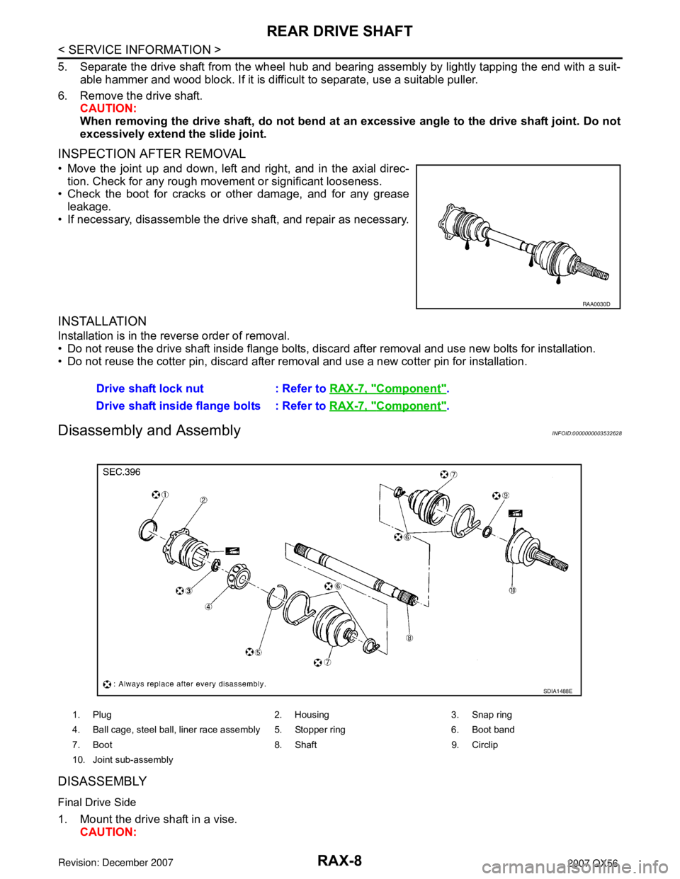
Disassembly and AssemblyINFOID:0000000003532628
DISASSEMBLY
Final Drive Side
1. Mount the drive shaft in a vise.
CAUTION:
RAA0030D
Drive shaft lock nut : Refer to RAX-7, "Component".
Drive shaft inside flange bolts : Refer to RAX-7, "
Component".
1. Plug 2. Housing 3. Snap ring
4. Ball cage, steel ball, liner race assembly 5. Stopper ring 6. Boot band
7. Boot 8. Shaft 9. Circlip
10. Joint sub-assembly
SDIA1488E