2007 INFINITI QX56 battery replacement
[x] Cancel search: battery replacementPage 2228 of 3061
HEADLAMP (FOR USA)
LT-21
< SERVICE INFORMATION >
C
D
E
F
G
H
I
J
L
MA
B
LT
N
O
P
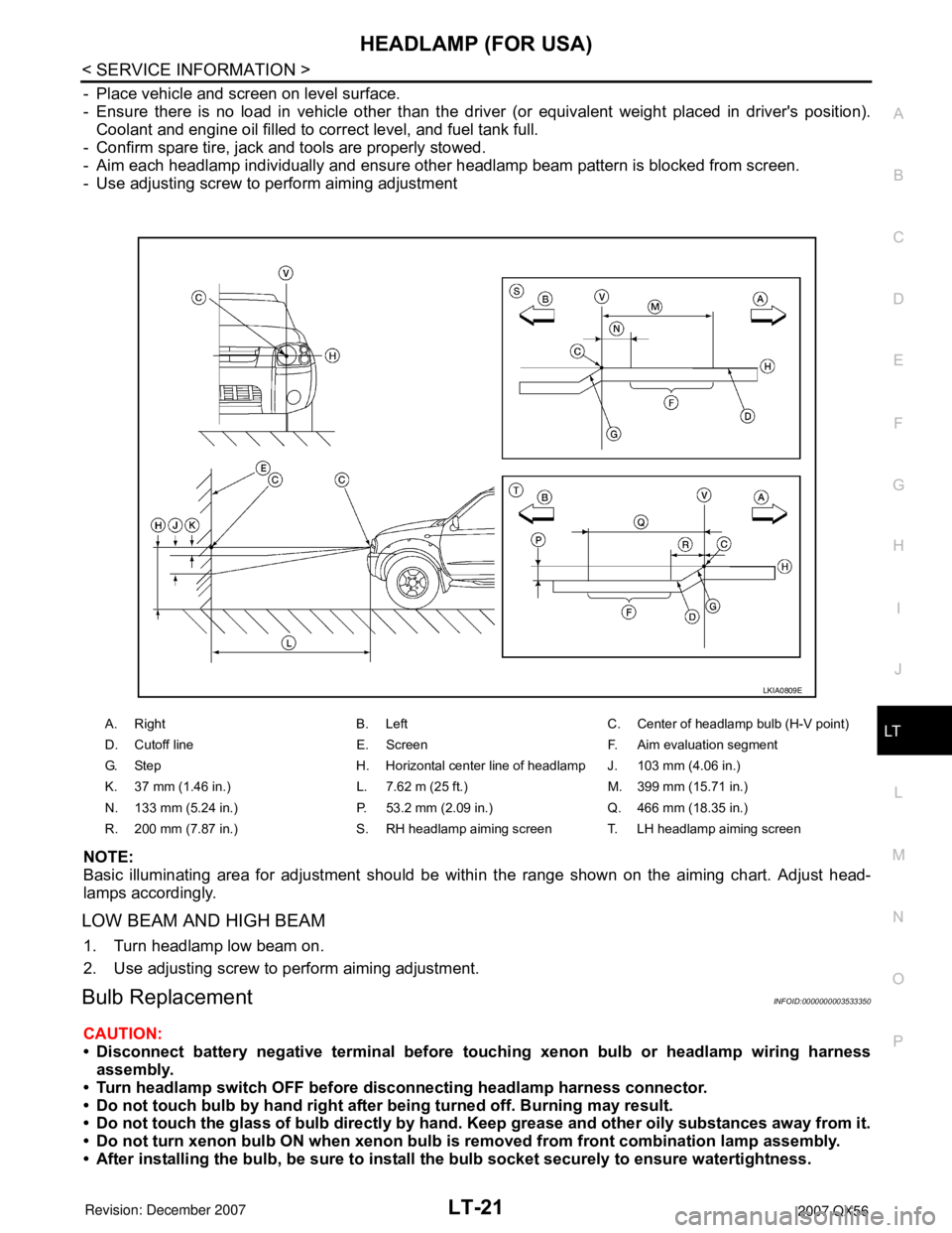
- Place vehicle and screen on level surface.
- Ensure there is no load in vehicle other than the driver (or equivalent weight placed in driver's position).
Coolant and engine oil filled to correct level, and fuel tank full.
- Confirm spare tire, jack and tools are properly stowed.
- Aim each headlamp individually and ensure other headlamp beam pattern is blocked from screen.
- Use adjusting screw to perform aiming adjustment
NOTE:
Basic illuminating area for adjustment should be within the range shown on the aiming chart. Adjust head-
lamps accordingly.
LOW BEAM AND HIGH BEAM
1. Turn headlamp low beam on.
2. Use adjusting screw to perform aiming adjustment.
Bulb ReplacementINFOID:0000000003533350
CAUTION:
• Disconnect battery negative terminal before touching xenon bulb or headlamp wiring harness
assembly.
• Turn headlamp switch OFF before disconnecting headlamp harness connector.
• Do not touch bulb by hand right after being turned off. Burning may result.
• Do not touch the glass of bulb directly by hand. Keep grease and other oily substances away from it.
• Do not turn xenon bulb ON when xenon bulb is removed from front combination lamp assembly.
• After installing the bulb, be sure to install the bulb socket securely to ensure watertightness.
A. Right B. Left C. Center of headlamp bulb (H-V point)
D. Cutoff line E. Screen F. Aim evaluation segment
G. Step H. Horizontal center line of headlamp J. 103 mm (4.06 in.)
K. 37 mm (1.46 in.) L. 7.62 m (25 ft.) M. 399 mm (15.71 in.)
N. 133 mm (5.24 in.) P. 53.2 mm (2.09 in.) Q. 466 mm (18.35 in.)
R. 200 mm (7.87 in.) S. RH headlamp aiming screen T. LH headlamp aiming screen
LKIA0809E
Page 2261 of 3061
LT-54
< SERVICE INFORMATION >
FRONT FOG LAMP
4.CHECK IPDM E/R
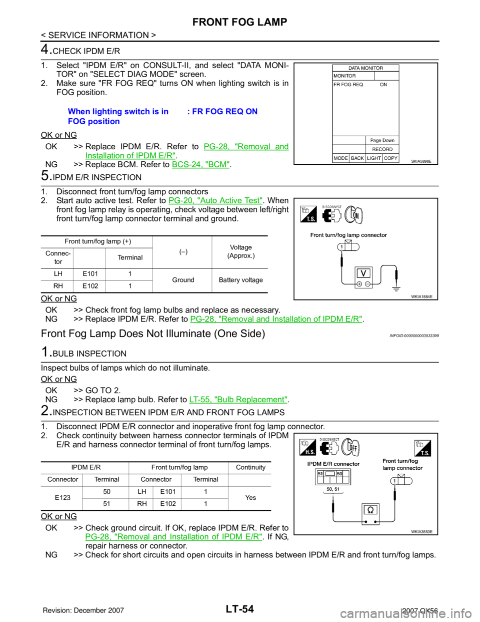
1. Select "IPDM E/R" on CONSULT-II, and select "DATA MONI-
TOR" on "SELECT DIAG MODE" screen.
2. Make sure "FR FOG REQ" turns ON when lighting switch is in
FOG position.
OK or NG
OK >> Replace IPDM E/R. Refer to PG-28, "Removal and
Installation of IPDM E/R".
NG >> Replace BCM. Refer to BCS-24, "
BCM".
5.IPDM E/R INSPECTION
1. Disconnect front turn/fog lamp connectors
2. Start auto active test. Refer to PG-20, "
Auto Active Test". When
front fog lamp relay is operating, check voltage between left/right
front turn/fog lamp connector terminal and ground.
OK or NG
OK >> Check front fog lamp bulbs and replace as necessary.
NG >> Replace IPDM E/R. Refer to PG-28, "
Removal and Installation of IPDM E/R".
Front Fog Lamp Does Not Illuminate (One Side)INFOID:0000000003533399
1.BULB INSPECTION
Inspect bulbs of lamps which do not illuminate.
OK or NG
OK >> GO TO 2.
NG >> Replace lamp bulb. Refer to LT-55, "
Bulb Replacement".
2.INSPECTION BETWEEN IPDM E/R AND FRONT FOG LAMPS
1. Disconnect IPDM E/R connector and inoperative front fog lamp connector.
2. Check continuity between harness connector terminals of IPDM
E/R and harness connector terminal of front turn/fog lamps.
OK or NG
OK >> Check ground circuit. If OK, replace IPDM E/R. Refer to
PG-28, "
Removal and Installation of IPDM E/R". If NG,
repair harness or connector.
NG >> Check for short circuits and open circuits in harness between IPDM E/R and front turn/fog lamps. When lighting switch is in
FOG position: FR FOG REQ ON
SKIA5898E
Front turn/fog lamp (+)
(–)Vo l ta g e
(Approx.) Connec-
torTe r m i n a l
LH E101 1
Ground Battery voltage
RH E102 1
WKIA1884E
IPDM E/R Front turn/fog lamp Continuity
Connector Terminal Connector Terminal
E12350 LH E101 1
Ye s
51 RH E102 1
WKIA3553E
Page 2792 of 3061
![INFINITI QX56 2007 Factory Service Manual SRS-22
< SERVICE INFORMATION >
TROUBLE DIAGNOSIS
Diagnostic code is displayed on "SELF-DIAG [CURRENT]".
If no malfunction is detected on "SELF-DIAG [CURRENT]", but mal-
function is detected in "SRS Op INFINITI QX56 2007 Factory Service Manual SRS-22
< SERVICE INFORMATION >
TROUBLE DIAGNOSIS
Diagnostic code is displayed on "SELF-DIAG [CURRENT]".
If no malfunction is detected on "SELF-DIAG [CURRENT]", but mal-
function is detected in "SRS Op](/manual-img/42/57029/w960_57029-2791.png)
SRS-22
< SERVICE INFORMATION >
TROUBLE DIAGNOSIS
Diagnostic code is displayed on "SELF-DIAG [CURRENT]".
If no malfunction is detected on "SELF-DIAG [CURRENT]", but mal-
function is detected in "SRS Operation Check", the following cases
may exist:
• "SELF-DIAG [PAST]" memory might not be erased.
• The SRS system malfunctions intermittently.
Refer to "DIAGNOSTIC PROCEDURE 4".
CONSULT-II Diagnostic Code Chart
WHIA0151E
SRS701
Diagnostic item ExplanationRepair order
Recheck SRS at each replacement
NO DTC IS DETECTEDMalfunction is indicat-
ed by the “AIR BAG”
warning lamp in User
mode.Low battery voltage (Less than 9V) 1. Go to SC-4
.
2. Go to "DIAGNOSTIC PROCE-
DURE 3" .
“SELF-DIAG [PAST]” memory might
not be erased.Go to "DIAGNOSTIC PROCEDURE 4"
.
Intermittent malfunction has been
detected in the past.Go to "DIAGNOSTIC PROCEDURE 5"
.
No malfunction is detected in User mode. —
DRIVER AIRBAG MODULE
[OPEN]
[B1049] or [B1054]Driver air bag module circuit is open (including the spiral ca-
ble).1. Visually check the wiring harness
connection.
2. Replace the harness if it has visi-
ble damage.
3. Replace driver air bag module.
4. Replace the spiral cable.
5. Replace the air bag diagnosis
sensor unit.
6. Replace the related harness. DRIVER AIRBAG MODULE
[VB-SHORT]
[B1050] or [B1055]Driver air bag module circuit is shorted to some power supply
circuit (including the spiral cable).
DRIVER AIRBAG MODULE
[GND-SHORT]
[B1051] or [B1056]Driver air bag module circuit is shorted to ground (including
the spiral cable).
DRIVER AIRBAG MODULE
[SHORT]
[B1052] or [B1057]Driver air bag module circuits are shorted to each other.
Page 2798 of 3061
SRS-28
< SERVICE INFORMATION >
TROUBLE DIAGNOSIS
Check SRS Intermittent Malfunction Using CONSULT-II—Diagnosis Mode
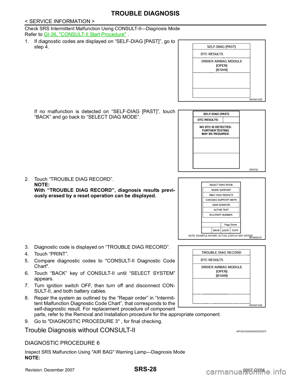
Refer to GI-36, "CONSULT-II Start Procedure" .
1. If diagnostic codes are displayed on “SELF-DIAG [PAST]”, go to
step 4.
If no malfunction is detected on “SELF-DIAG [PAST]”, touch
“BACK” and go back to “SELECT DIAG MODE”.
2. Touch “TROUBLE DIAG RECORD”.
NOTE:
With “TROUBLE DIAG RECORD”, diagnosis results previ-
ously erased by a reset operation can be displayed.
3. Diagnostic code is displayed on “TROUBLE DIAG RECORD”.
4. Touch “PRINT”.
5. Compare diagnostic codes to "CONSULT-II Diagnostic Code
Chart".
6. Touch “BACK” key of CONSULT-II until “SELECT SYSTEM”
appears.
7. Turn ignition switch OFF, then turn off and disconnect CON-
SULT-II, and both battery cables.
8. Repair the system as outlined by the “Repair order” in “Intermit-
tent Malfunction Diagnostic Code Chart”, that corresponds to the
self-diagnostic result. For replacement procedure of component
parts, refer to the Removal and Installation procedure for the appropriate component.
9. Go to "DIAGNOSTIC PROCEDURE 3" , for final checking.
Trouble Diagnosis without CONSULT-IIINFOID:0000000003532870
DIAGNOSTIC PROCEDURE 6
Inspect SRS Malfunction Using "AIR BAG" Warning Lamp—Diagnosis Mode
NOTE:
WHIA0152E
SRS702
BCIA0031E
WHIA0153E
Page 2809 of 3061
FRONT PASSENGER AIR BAG MODULE
SRS-39
< SERVICE INFORMATION >
C
D
E
F
G
I
J
K
L
MA
B
SRS
N
O
P
FRONT PASSENGER AIR BAG MODULE
Removal and InstallationINFOID:0000000003532875
The passenger air bag module originally installed in the vehicle uses direct-connect style harness connectors.
Service replacement passenger air bag modules use tab-locking style harness connectors. If the passenger
air bag module is replaced or if the direct-connect harness connectors are damaged, the vehicle wiring har-
ness must be modified to allow connection of the service replacement passenger air bag module. Refer to
"WIRING HARNESS MODIFICATION" for wiring harness modification procedure.
REMOVAL
CAUTION:
• Do not attempt to repair or replace damaged direct-connect front passenger air bag module connec-
tors. If a direct-connect harness connector is damaged, the front passenger air bag must be
replaced and the wiring harness modified.
• Before servicing SRS, turn the ignition switch off, disconnect both battery cables and wait at least 3
minutes.
• Always work from the side of or under front passenger air bag module.
1. Remove the glove box. Refer to IP-10
.
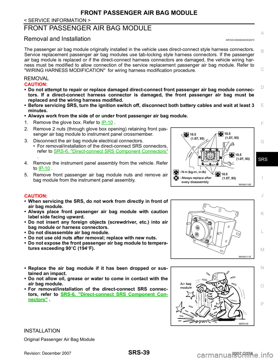
2. Remove 2 nuts (through glove box opening) retaining front pas-
senger air bag module to instrument panel crossmember.
3. Disconnect the air bag module electrical connectors.
• For removal/installation of the direct-connect SRS connectors,
refer to SRS-6, "
Direct-connect SRS Component Connectors"
.
4. Remove the instrument panel assembly from the vehicle. Refer
to IP-10
.
5. Remove front passenger air bag module nuts and remove air
bag module from the instrument panel assembly.
CAUTION:
• When servicing the SRS, do not work from directly in front of
air bag module.
• Always place front passenger air bag module with caution
label side facing upward.
• Do not insert any foreign objects (screwdriver, etc.) into air
bag module or harness connectors.
• Do not disassemble air bag module.
• Do not use old nuts after removal; replace with new nuts.
• Do not expose the front passenger air bag module to tempera-
tures exceeding 90°C (194°F).
• Replace the air bag module if it has been dropped or sus-
tained an impact.
• Do not allow oil, grease or water to come in contact with the
air bag module.
• For removal/installation of the direct-connect SRS connec-
tors, refer to SRS-6, "
Direct-connect SRS Component Con-
nectors" .
INSTALLATION
Original Passenger Air Bag Module
WHIA0110E
WHIA0111E
SBF814E
Page 2810 of 3061
SRS-40
< SERVICE INFORMATION >
FRONT PASSENGER AIR BAG MODULE
Installation is in the reverse order of removal.
• For removal/installation of the direct-connect SRS connectors, refer to SRS-6, "
Direct-connect SRS Compo-
nent Connectors".
CAUTION:
• Always work from the side of or under front passenger air bag module.
• After the work is completed, perform self-diagnosis to check that no malfunction is detected. Refer
to SRS-20, "
SRS Operation Check".
Service Replacement Passenger Air Bag Module
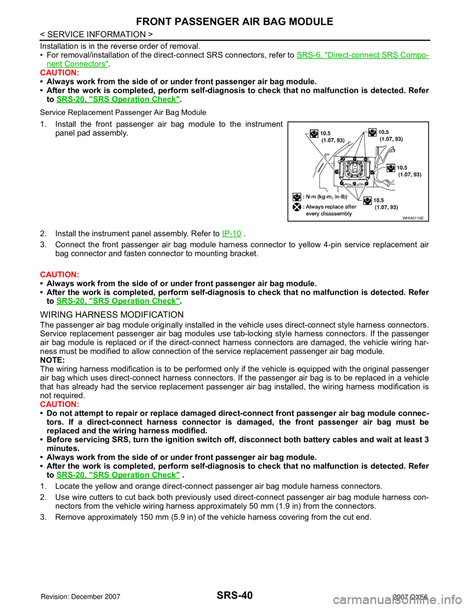
1. Install the front passenger air bag module to the instrument
panel pad assembly.
2. Install the instrument panel assembly. Refer to IP-10
.
3. Connect the front passenger air bag module harness connector to yellow 4-pin service replacement air
bag connector and fasten connector to mounting bracket.
CAUTION:
• Always work from the side of or under front passenger air bag module.
• After the work is completed, perform self-diagnosis to check that no malfunction is detected. Refer
to SRS-20, "
SRS Operation Check".
WIRING HARNESS MODIFICATION
The passenger air bag module originally installed in the vehicle uses direct-connect style harness connectors.
Service replacement passenger air bag modules use tab-locking style harness connectors. If the passenger
air bag module is replaced or if the direct-connect harness connectors are damaged, the vehicle wiring har-
ness must be modified to allow connection of the service replacement passenger air bag module.
NOTE:
The wiring harness modification is to be performed only if the vehicle is equipped with the original passenger
air bag which uses direct-connect harness connectors. If the passenger air bag is to be replaced in a vehicle
that has already had the service replacement passenger air bag installed, the wiring harness modification is
not required.
CAUTION:
• Do not attempt to repair or replace damaged direct-connect front passenger air bag module connec-
tors. If a direct-connect harness connector is damaged, the front passenger air bag must be
replaced and the wiring harness modified.
• Before servicing SRS, turn the ignition switch off, disconnect both battery cables and wait at least 3
minutes.
• Always work from the side of or under front passenger air bag module.
• After the work is completed, perform self-diagnosis to check that no malfunction is detected. Refer
to SRS-20, "
SRS Operation Check" .
1. Locate the yellow and orange direct-connect passenger air bag module harness connectors.
2. Use wire cutters to cut back both previously used direct-connect passenger air bag module harness con-
nectors from the vehicle wiring harness approximately 50 mm (1.9 in) from the connectors.
3. Remove approximately 150 mm (5.9 in) of the vehicle harness covering from the cut end.
WHIA0110E
Page 2937 of 3061
TRANSFER CONTROL UNIT
TF-115
< SERVICE INFORMATION >
C
E
F
G
H
I
J
K
L
MA
B
TF
N
O
P
TRANSFER CONTROL UNIT
Removal and InstallationINFOID:0000000003532562
REMOVAL
1. Set transfer state as 2WD when 4WD shift switch is at 2WD, or as AUTO when 4WD shift switch is at
AUTO.
CAUTION:
When removing transfer control unit, transfer state must be at 2WD or AUTO.
2. Turn the ignition switch OFF and disconnect negative battery terminal.
3. Remove the glove box assembly. Refer to IP-10, "
Removal and Installation".
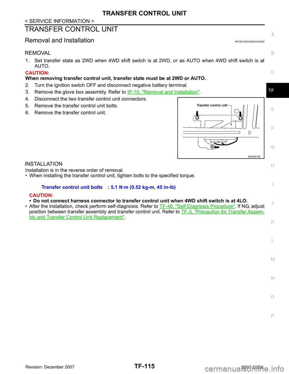
4. Disconnect the two transfer control unit connectors.
5. Remove the transfer control unit bolts.
6. Remove the transfer control unit.
INSTALLATION
Installation is in the reverse order of removal.
• When installing the transfer control unit, tighten bolts to the specified torque.
CAUTION:
• Do not connect harness connector to transfer control unit when 4WD shift switch is at 4LO.
• After the installation, check perform self-diagnosis. Refer to TF-48, "
Self-Diagnosis Procedure". If NG, adjust
position between transfer assembly and transfer control unit. Refer to TF-3, "
Precaution for Transfer Assem-
bly and Transfer Control Unit Replacement".
BDIA0014E
Transfer control unit bolts : 5.1 N·m (0.52 kg-m, 45 in-lb)