2007 INFINITI QX56 ABS
[x] Cancel search: ABSPage 1197 of 3061
EC-114
< SERVICE INFORMATION >
TROUBLE DIAGNOSIS
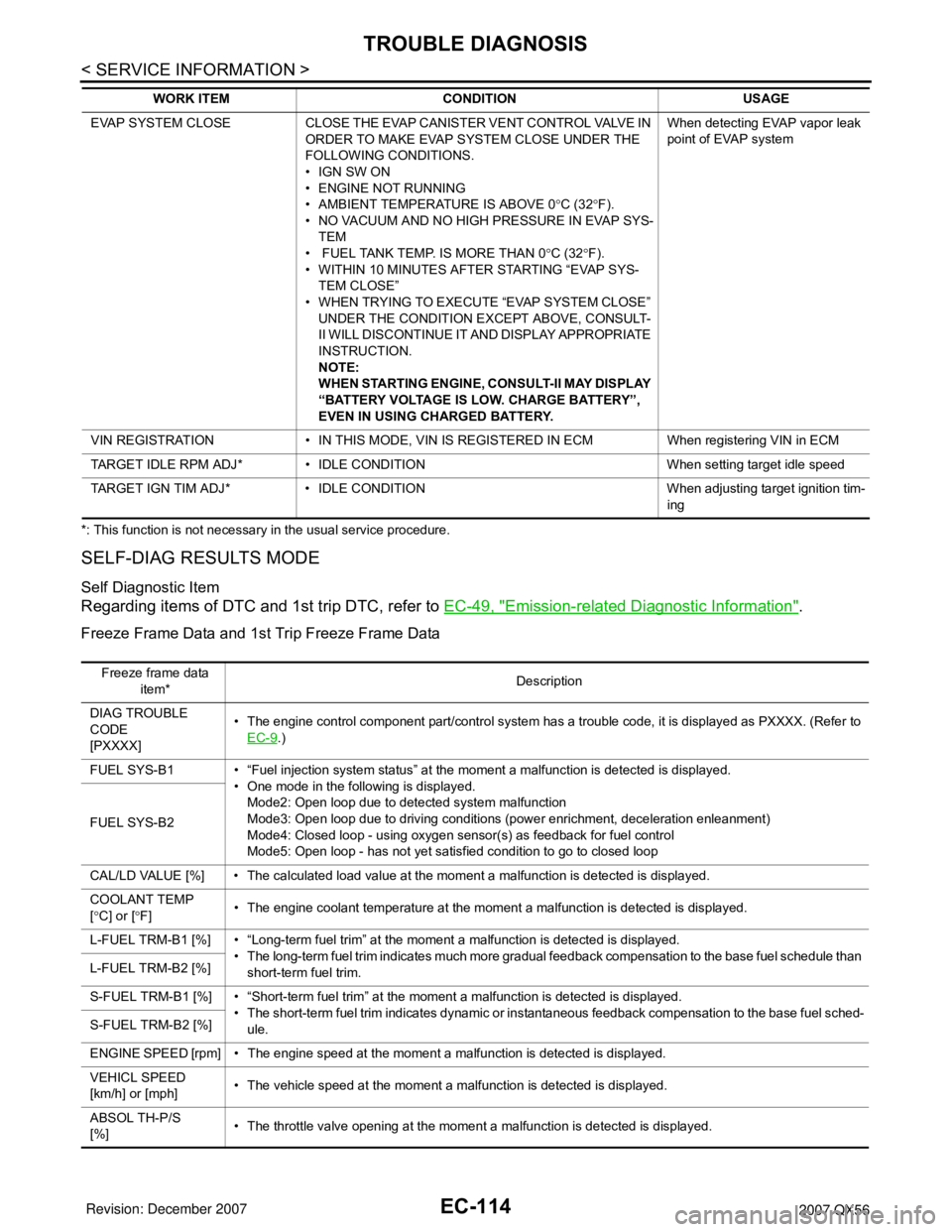
*: This function is not necessary in the usual service procedure.
SELF-DIAG RESULTS MODE
Self Diagnostic Item
Regarding items of DTC and 1st trip DTC, refer to EC-49, "Emission-related Diagnostic Information".
Freeze Frame Data and 1st Trip Freeze Frame Data
EVAP SYSTEM CLOSE CLOSE THE EVAP CANISTER VENT CONTROL VALVE IN
ORDER TO MAKE EVAP SYSTEM CLOSE UNDER THE
FOLLOWING CONDITIONS.
• IGN SW ON
• ENGINE NOT RUNNING
• AMBIENT TEMPERATURE IS ABOVE 0°C (32°F).
• NO VACUUM AND NO HIGH PRESSURE IN EVAP SYS-
TEM
• FUEL TANK TEMP. IS MORE THAN 0°C (32°F).
• WITHIN 10 MINUTES AFTER STARTING “EVAP SYS-
TEM CLOSE”
• WHEN TRYING TO EXECUTE “EVAP SYSTEM CLOSE”
UNDER THE CONDITION EXCEPT ABOVE, CONSULT-
II WILL DISCONTINUE IT AND DISPLAY APPROPRIATE
INSTRUCTION.
NOTE:
WHEN STARTING ENGINE, CONSULT-II MAY DISPLAY
“BATTERY VOLTAGE IS LOW. CHARGE BATTERY”,
EVEN IN USING CHARGED BATTERY.When detecting EVAP vapor leak
point of EVAP system
VIN REGISTRATION • IN THIS MODE, VIN IS REGISTERED IN ECM When registering VIN in ECM
TARGET IDLE RPM ADJ* • IDLE CONDITION When setting target idle speed
TARGET IGN TIM ADJ* • IDLE CONDITION When adjusting target ignition tim-
ing WORK ITEM CONDITION USAGE
Freeze frame data
item*Description
DIAG TROUBLE
CODE
[PXXXX]• The engine control component part/control system has a trouble code, it is displayed as PXXXX. (Refer to
EC-9
.)
FUEL SYS-B1 • “Fuel injection system status” at the moment a malfunction is detected is displayed.
• One mode in the following is displayed.
Mode2: Open loop due to detected system malfunction
Mode3: Open loop due to driving conditions (power enrichment, deceleration enleanment)
Mode4: Closed loop - using oxygen sensor(s) as feedback for fuel control
Mode5: Open loop - has not yet satisfied condition to go to closed loop FUEL SYS-B2
CAL/LD VALUE [%] • The calculated load value at the moment a malfunction is detected is displayed.
COOLANT TEMP
[°C] or [°F]• The engine coolant temperature at the moment a malfunction is detected is displayed.
L-FUEL TRM-B1 [%] • “Long-term fuel trim” at the moment a malfunction is detected is displayed.
• The long-term fuel trim indicates much more gradual feedback compensation to the base fuel schedule than
short-term fuel trim. L-FUEL TRM-B2 [%]
S-FUEL TRM-B1 [%] • “Short-term fuel trim” at the moment a malfunction is detected is displayed.
• The short-term fuel trim indicates dynamic or instantaneous feedback compensation to the base fuel sched-
ule. S-FUEL TRM-B2 [%]
ENGINE SPEED [rpm] • The engine speed at the moment a malfunction is detected is displayed.
VEHICL SPEED
[km/h] or [mph]• The vehicle speed at the moment a malfunction is detected is displayed.
ABSOL TH-P/S
[%]• The throttle valve opening at the moment a malfunction is detected is displayed.
Page 1512 of 3061
DTC P0500 VSS
EC-429
< SERVICE INFORMATION >
C
D
E
F
G
H
I
J
K
L
MA
EC
N
P O
DTC P0500 VSS
DescriptionINFOID:0000000003531931
NOTE:
•If DTC P0500 is displayed with DTC U1000 or U1001, first perform the trouble diagnosis for DTC
U1000, U1001. Refer to EC-145
.
•If DTC P0500 is displayed with DTC U1010, first perform the trouble diagnosis for DTC U1010. Refer
to EC-147
.
The vehicle speed signal is sent to the combination meter from the “ABS actuator and electric unit (control
unit)” by CAN communication line. The c combination meter then sends a signal to the ECM by CAN commu-
nication line.
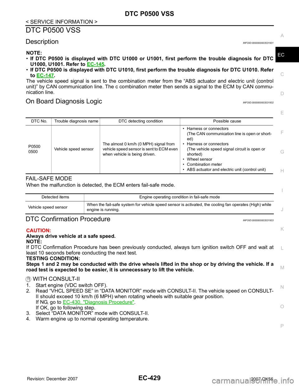
On Board Diagnosis LogicINFOID:0000000003531932
FA I L - S A F E M O D E
When the malfunction is detected, the ECM enters fail-safe mode.
DTC Confirmation ProcedureINFOID:0000000003531933
CAUTION:
Always drive vehicle at a safe speed.
NOTE:
If DTC Confirmation Procedure has been previously conducted, always turn ignition switch OFF and wait at
least 10 seconds before conducting the next test.
TESTING CONDITION:
Steps 1 and 2 may be conducted with the drive wheels lifted in the shop or by driving the vehicle. If a
road test is expected to be easier, it is unnecessary to lift the vehicle.
WITH CONSULT-II
1. Start engine (VDC switch OFF).
2. Read “VHCL SPEED SE” in “DATA MONITOR” mode with CONSULT-II. The vehicle speed on CONSULT-
II should exceed 10 km/h (6 MPH) when rotating wheels with suitable gear position.
If NG, go to EC-430, "
Diagnosis Procedure".
If OK, go to following step.
3. Select “DATA MONITOR” mode with CONSULT-II.
4. Warm engine up to normal operating temperature.
DTC No. Trouble diagnosis name DTC detecting condition Possible cause
P0500
0500Vehicle speed sensorThe almost 0 km/h (0 MPH) signal from
vehicle speed sensor is sent to ECM even
when vehicle is being driven.• Harness or connectors
(The CAN communication line is open or short-
ed)
• Harness or connectors
(The vehicle speed signal circuit is open or
shorted)
• Wheel sensor
• Combination meter
• ABS actuator and electric unit (control unit)
Detected items Engine operating condition in fail-safe mode
Vehicle speed sensorWhen the fail-safe system for vehicle speed sensor is activated, the cooling fan operates (High) while
engine is running.
Page 1513 of 3061
EC-430
< SERVICE INFORMATION >
DTC P0500 VSS
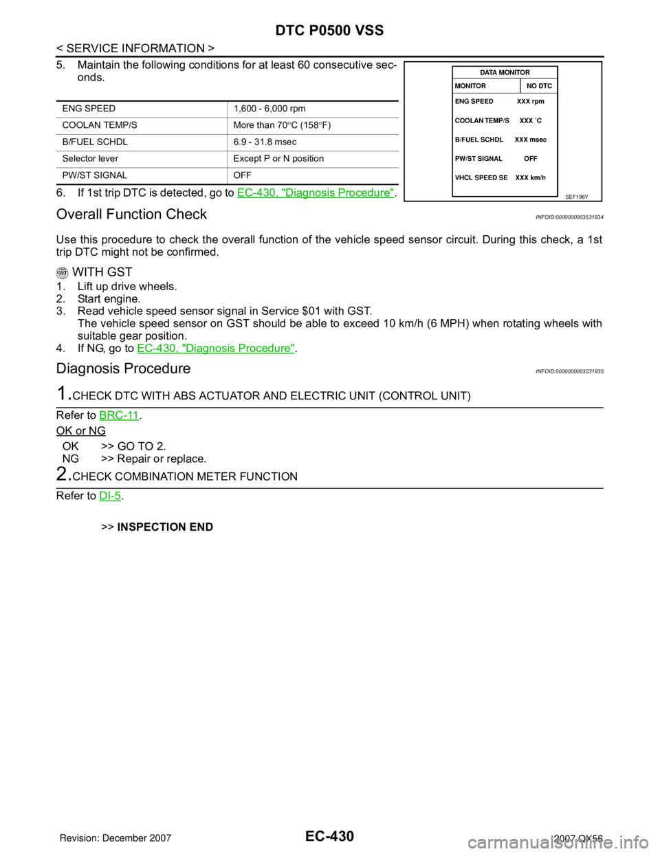
5. Maintain the following conditions for at least 60 consecutive sec-
onds.
6. If 1st trip DTC is detected, go to EC-430, "
Diagnosis Procedure".
Overall Function CheckINFOID:0000000003531934
Use this procedure to check the overall function of the vehicle speed sensor circuit. During this check, a 1st
trip DTC might not be confirmed.
WITH GST
1. Lift up drive wheels.
2. Start engine.
3. Read vehicle speed sensor signal in Service $01 with GST.
The vehicle speed sensor on GST should be able to exceed 10 km/h (6 MPH) when rotating wheels with
suitable gear position.
4. If NG, go to EC-430, "
Diagnosis Procedure".
Diagnosis ProcedureINFOID:0000000003531935
1.CHECK DTC WITH ABS ACTUATOR AND ELECTRIC UNIT (CONTROL UNIT)
Refer to BRC-11
.
OK or NG
OK >> GO TO 2.
NG >> Repair or replace.
2.CHECK COMBINATION METER FUNCTION
Refer to DI-5
.
>>INSPECTION END
ENG SPEED 1,600 - 6,000 rpm
COOLAN TEMP/S More than 70°C (158°F)
B/FUEL SCHDL 6.9 - 31.8 msec
Selector lever Except P or N position
PW/ST SIGNAL OFF
SEF196Y
Page 1550 of 3061
DTC P1211 TCS CONTROL UNIT
EC-467
< SERVICE INFORMATION >
C
D
E
F
G
H
I
J
K
L
MA
EC
N
P O
DTC P1211 TCS CONTROL UNIT
DescriptionINFOID:0000000003531981
The malfunction information related to TCS is transferred through the CAN communication line from “ABS
actuator and electric unit (control unit)” to ECM.
Be sure to erase the malfunction information such as DTC not only for “ABS actuator and electric unit
(control unit)” but also for ECM after TCS related repair.
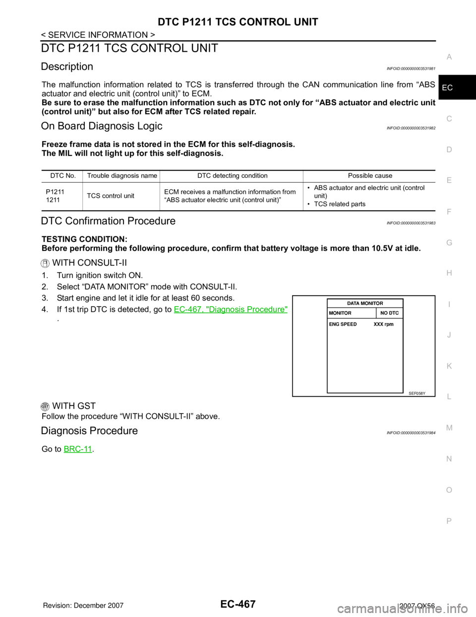
On Board Diagnosis LogicINFOID:0000000003531982
Freeze frame data is not stored in the ECM for this self-diagnosis.
The MIL will not light up for this self-diagnosis.
DTC Confirmation ProcedureINFOID:0000000003531983
TESTING CONDITION:
Before performing the following procedure, confirm that battery voltage is more than 10.5V at idle.
WITH CONSULT-II
1. Turn ignition switch ON.
2. Select “DATA MONITOR” mode with CONSULT-II.
3. Start engine and let it idle for at least 60 seconds.
4. If 1st trip DTC is detected, go to EC-467, "
Diagnosis Procedure"
.
WITH GST
Follow the procedure “WITH CONSULT-II” above.
Diagnosis ProcedureINFOID:0000000003531984
Go to BRC-11.
DTC No. Trouble diagnosis name DTC detecting condition Possible cause
P1211
1211TCS control unitECM receives a malfunction information from
“ABS actuator electric unit (control unit)”• ABS actuator and electric unit (control
unit)
• TCS related parts
SEF058Y
Page 1551 of 3061
EC-468
< SERVICE INFORMATION >
DTC P1212 TCS COMMUNICATION LINE
DTC P1212 TCS COMMUNICATION LINE
DescriptionINFOID:0000000003531985
NOTE:
•If DTC P1212 is displayed with DTC U1000 or U1001, first perform the trouble diagnosis for DTC
U1000, U1001. Refer to EC-145
.
•If DTC P1212 is displayed with DTC U1010, first perform the trouble diagnosis for DTC U1010. Refer
to EC-147
.
This CAN communication line is used to control the smooth engine operation during the TCS operation. Pulse
signals are exchanged between ECM and “ABS actuator and electric unit (control unit)”.
Be sure to erase the malfunction information such as DTC not only for “ABS actuator and electric unit
(control unit)” but also for ECM after TCS related repair.
On Board Diagnosis LogicINFOID:0000000003531986
Freeze frame data is not stored in the ECM for this self-diagnosis.
The MIL will not light up for this self-diagnosis.
DTC Confirmation ProcedureINFOID:0000000003531987
TESTING CONDITION:
Before performing the following procedure, confirm that battery voltage is more than 10.5V at idle.
WITH CONSULT-II
1. Turn ignition switch ON.
2. Select “DATA MONITOR” mode with CONSULT-II.
3. Start engine and let it idle for at least 10 seconds.
4. If 1st trip DTC is detected, go to EC-468, "
Diagnosis Procedure"
.
WITH GST
Follow the procedure “WITH CONSULT-II” above.
Diagnosis ProcedureINFOID:0000000003531988
Go to BRC-11.
DTC No. Trouble diagnosis name DTC detecting condition Possible cause
P1212
1212TCS communication lineECM can not receive the information from
“ABS actuator and electric unit (control
unit)” continuously.• Harness or connectors
(The CAN communication line is open or short-
ed.)
• ABS actuator and electric unit (control unit)
• Dead (Weak) battery
SEF058Y
Page 1618 of 3061
DTC P1574 ICC VEHICLE SPEED SENSOR
EC-535
< SERVICE INFORMATION >
C
D
E
F
G
H
I
J
K
L
MA
EC
N
P O
DTC P1574 ICC VEHICLE SPEED SENSOR
Component DescriptionINFOID:0000000003532070
The ECM receives two vehicle speed signals via CAN communication line. One is sent from “unified meter and
A/C amp.”, and the other is from TCM (Transmission control module). The ECM uses these signals for ICC
control. Refer to ACS-6
for ICC functions.
On Board Diagnosis LogicINFOID:0000000003532071
•This self-diagnosis has the one trip detection logic.
•The MIL will not light up for this self-diagnosis.
NOTE:
•If DTC P1574 is displayed with DTC U1000, U1001, first perform the trouble diagnosis for DTC U1000,
U1001. Refer to EC-145
.
•If DTC P1574 is displayed with DTC U1010, first perform the trouble diagnosis for DTC U1010. Refer
to EC-147
.
•If DTC P1574 is displayed with DTC P0500, first perform the trouble diagnosis for DTC P0500. Refer
to EC-429
.
•If DTC P1574 is displayed with DTC P0605, first perform the trouble diagnosis for DTC P0605. Refer
to EC-444
.
DTC Confirmation ProcedureINFOID:0000000003532072
CAUTION:
Always drive vehicle at a safe speed.
NOTE:
If DTC Confirmation Procedure has been previously conducted, always turn ignition switch OFF and wait at
least 10 seconds before conducting the next test.
TESTING CONDITION:
Step 3 may be conducted with the drive wheels lifted in the shop or by driving the vehicle. If a road test
is expected to be easier, it is unnecessary to lift the vehicle.
WITH CONSULT-II
1. Start engine.
2. Select “DATA MONITOR” mode with CONSULT-II.
3. Drive the vehicle at more than 40 km/h (25MPH).
4. If DTC is detected, go to EC-536, "
Diagnosis Procedure".
WITH GST
Follow the procedure “WITH CONSULT-II” above.
DTC No. Trouble Diagnosis Name DTC Detecting Condition Possible Cause
P1574
1574ICC vehicle speed sensorECM detects a difference between two vehicle
speed signals is out of the specified range.• Harness or connectors
(The CAN communication line is open or
shorted.)
• Combination meter
• ABS actuator and electric unit (control unit)
• Wheel sensor
•TCM
•ECM
SEF058Y
Page 1619 of 3061
EC-536
< SERVICE INFORMATION >
DTC P1574 ICC VEHICLE SPEED SENSOR
Diagnosis Procedure
INFOID:0000000003532073
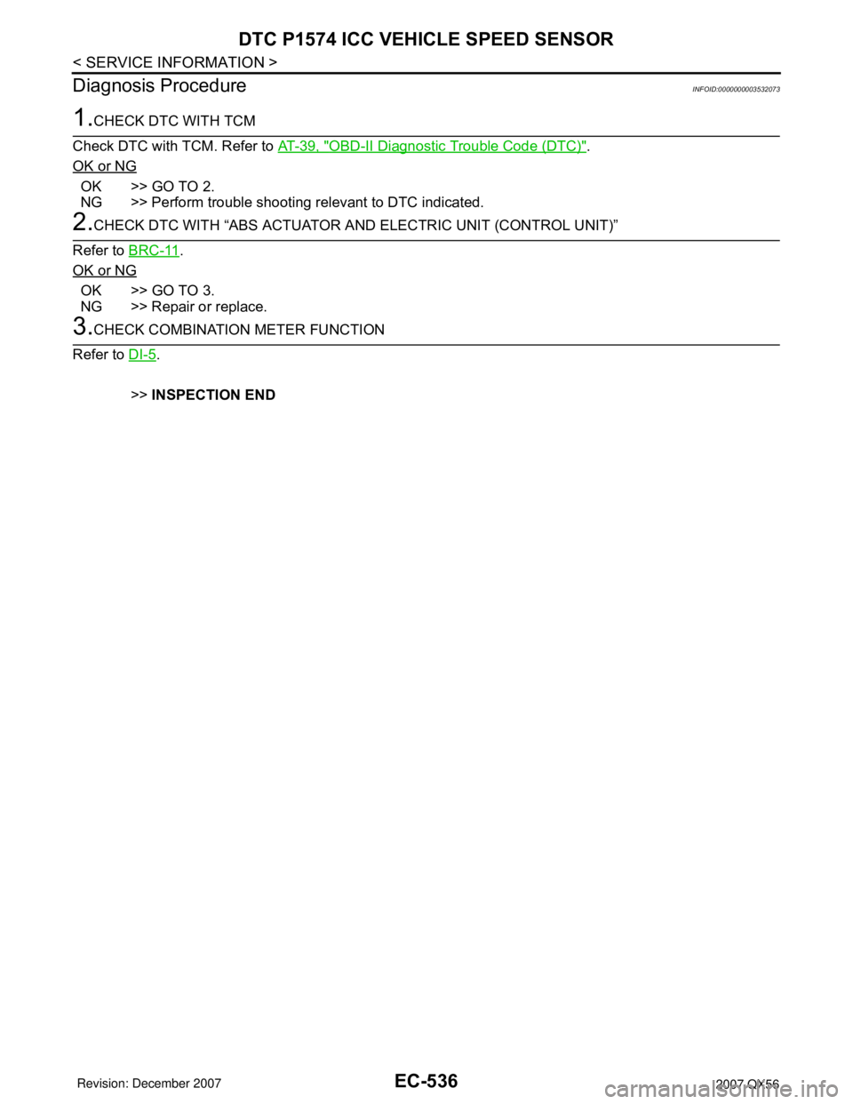
1.CHECK DTC WITH TCM
Check DTC with TCM. Refer to AT-39, "
OBD-II Diagnostic Trouble Code (DTC)".
OK or NG
OK >> GO TO 2.
NG >> Perform trouble shooting relevant to DTC indicated.
2.CHECK DTC WITH “ABS ACTUATOR AND ELECTRIC UNIT (CONTROL UNIT)”
Refer to BRC-11
.
OK or NG
OK >> GO TO 3.
NG >> Repair or replace.
3.CHECK COMBINATION METER FUNCTION
Refer to DI-5
.
>>INSPECTION END
Page 1620 of 3061
DTC P1574 ASCD VEHICLE SPEED SENSOR
EC-537
< SERVICE INFORMATION >
C
D
E
F
G
H
I
J
K
L
MA
EC
N
P O
DTC P1574 ASCD VEHICLE SPEED SENSOR
Component DescriptionINFOID:0000000003532074
The ECM receives two vehicle speed sensor signals via CAN communication line. One is sent from combina-
tion meter and the other is from TCM (Transmission control module). The ECM uses these signals for ASCD
control. Refer to EC-30
for ASCD functions.
On Board Diagnosis LogicINFOID:0000000003532075
•This self-diagnosis has the one trip detection logic.
•The MIL will not light up for this self-diagnosis.
NOTE:
•If DTC P1574 is displayed with DTC U1000, U1001, first perform the trouble diagnosis for DTC U1000,
U1001. Refer to EC-145
.
•If DTC P1574 is displayed with DTC U1010, first perform the trouble diagnosis for DTC U1010. Refer
to EC-147
.
•If DTC P1574 is displayed with DTC P0500, first perform the trouble diagnosis for DTC P0500. Refer
to EC-429
.
•If DTC P1574 is displayed with DTC P0605, first perform the trouble diagnosis for DTC P0605. Refer
to EC-444
.
DTC Confirmation ProcedureINFOID:0000000003532076
CAUTION:
Always drive vehicle at a safe speed.
NOTE:
If DTC Confirmation Procedure has been previously conducted, always turn ignition switch OFF and wait at
least 10 seconds before conducting the next test.
TESTING CONDITION:
Step 3 may be conducted with the drive wheels lifted in the shop or by driving the vehicle. If a road test
is expected to be easier, it is unnecessary to lift the vehicle.
WITH CONSULT-II
1. Start engine (VDC switch OFF).
2. Select “DATA MONITOR” mode with CONSULT-II.
3. Drive the vehicle at more than 40 km/h (25 MPH).
4. If DTC is detected, go to EC-538, "
Diagnosis Procedure" .
WITH GST
Follow the procedure “WITH CONSULT-II” above.
DTC No.Trouble Diagnosis
NameDTC Detecting Condition Possible Cause
P1574
1574ASCD vehicle speed
sensorECM detects a difference between two vehicle
speed signals is out of the specified range.• Harness or connectors
(The CAN communication line is open or
shorted.)
• Combination meter
• ABS actuator and electric unit (control unit)
• Wheel sensor
•TCM
•ECM
SEF058Y