2007 INFINITI QX56 brake fluid
[x] Cancel search: brake fluidPage 1022 of 3061
COMBINATION METERSDI-11
< SERVICE INFORMATION >
C
DE
F
G H
I
J
L
M A
B
DI
N
O P
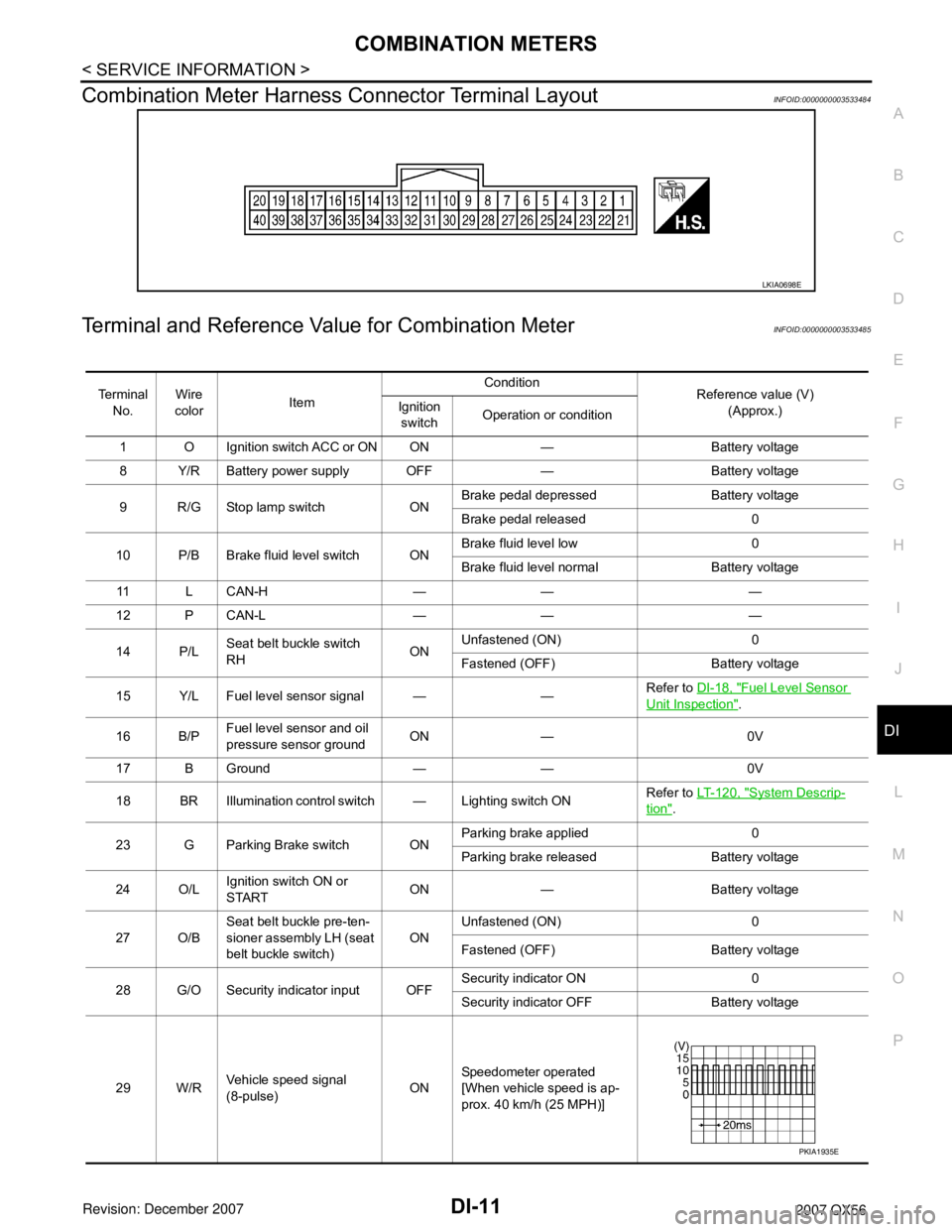
Combination Meter Harness Connector Terminal LayoutINFOID:0000000003533484
Terminal and Reference Va lue for Combination MeterINFOID:0000000003533485
LKIA0698E
Te r m i n a l
No. Wire
color Item Condition
Reference value (V)
(Approx.)
Ignition
switch Operation or condition
1 O Ignition switch ACC or ON ON — Battery voltage
8 Y/R Battery power supply OFF — Battery voltage
9 R/G Stop lamp switch ON Brake pedal depressed Battery voltage
Brake pedal released 0
10 P/B Brake fluid level switch ON Brake fluid level low 0
Brake fluid level normal Battery voltage
11 L C A N - H — — —
12 P CAN-L — — —
14 P/L Seat belt buckle switch
RH ONUnfastened (ON) 0
Fastened (OFF) Battery voltage
15 Y/L Fuel level sensor signal — — Refer to
DI-18, "
Fuel Level Sensor
Unit Inspection".
16 B/P Fuel level sensor and oil
pressure sensor ground ON — 0V
17 B Ground — — 0V
18 BR Illumination control switch — Lighting switch ON Refer to
LT- 1 2 0 , "
System Descrip-
tion".
23 G Parking Brake switch ON Parking brake applied 0
Parking brake released Battery voltage
24 O/L Ignition switch ON or
START ON — Battery voltage
27 O/B Seat belt buckle pre-ten-
sioner assembly LH (seat
belt buckle switch) ON
Unfastened (ON) 0
Fastened (OFF) Battery voltage
28 G/O Security indicator input OFF Security indicator ON 0
Security indicator
OFF Battery voltage
29 W/R Vehicle speed signal
(8-pulse) ONSpeedometer operated
[When vehicle speed is ap-
prox. 40 km/h (25 MPH)]
PKIA1935E
Page 1179 of 3061
EC-96
< SERVICE INFORMATION >
TROUBLE DIAGNOSIS
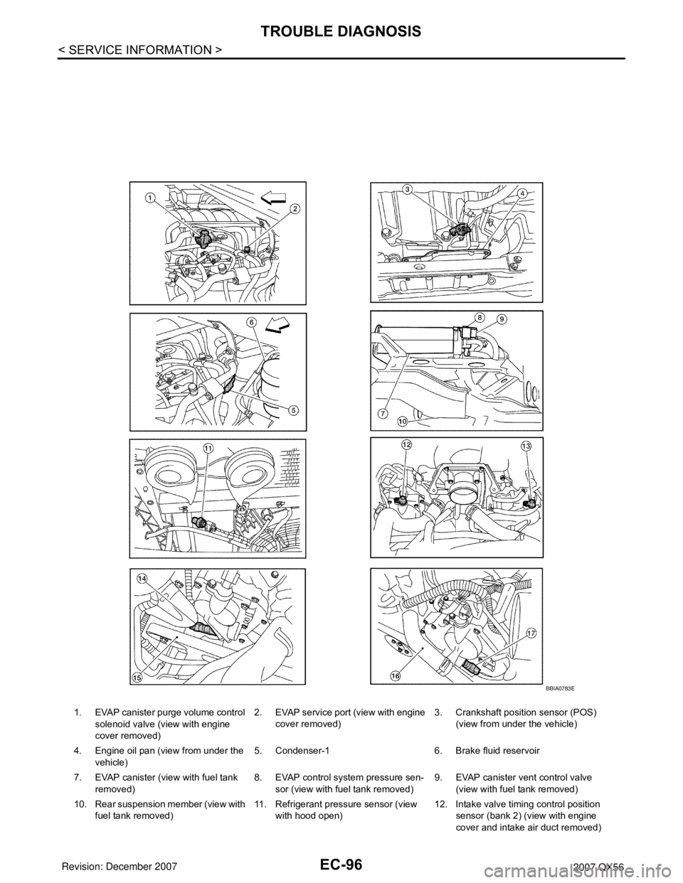
1. EVAP canister purge volume control
solenoid valve (view with engine
cover removed)2. EVAP service port (view with engine
cover removed)3. Crankshaft position sensor (POS)
(view from under the vehicle)
4. Engine oil pan (view from under the
vehicle)5. Condenser-1 6. Brake fluid reservoir
7. EVAP canister (view with fuel tank
removed)8. EVAP control system pressure sen-
sor (view with fuel tank removed)9. EVAP canister vent control valve
(view with fuel tank removed)
10. Rear suspension member (view with
fuel tank removed)11. Refrigerant pressure sensor (view
with hood open)12. Intake valve timing control position
sensor (bank 2) (view with engine
cover and intake air duct removed)
BBIA0783E
Page 1847 of 3061
ENGINE ASSEMBLY
EM-77
< SERVICE INFORMATION >
C
D
E
F
G
H
I
J
K
L
MA
EM
N
P O
• Start engine. With engine speed increased, check again for fuel leakage at connection points.
• Run engine to check for unusual noise and vibration.
• Warm up engine thoroughly to make sure there is no leakage of fuel, exhaust gas, or any oils/fluids including
engine oil and engine coolant.
• Bleed air from passages in lines and hoses, such as in cooling system.
• After cooling down the engine, again check oil/fluid levels including engine oil and engine coolant. Refill to
specified level if necessary.
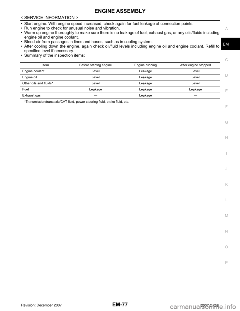
• Summary of the inspection items:
*Transmission/transaxle/CVT fluid, power steering fluid, brake fluid, etc.Item Before starting engine Engine running After engine stopped
Engine coolant Level Leakage Level
Engine oil Level Leakage Level
Other oils and fluids* Level Leakage Level
Fuel Leakage Leakage Leakage
Exhaust gas — Leakage —
Page 1969 of 3061
PRECAUTIONS
GI-3
< SERVICE INFORMATION >
C
D
E
F
G
H
I
J
K
L
MB
GI
N
O
P
General PrecautionINFOID:0000000003531471
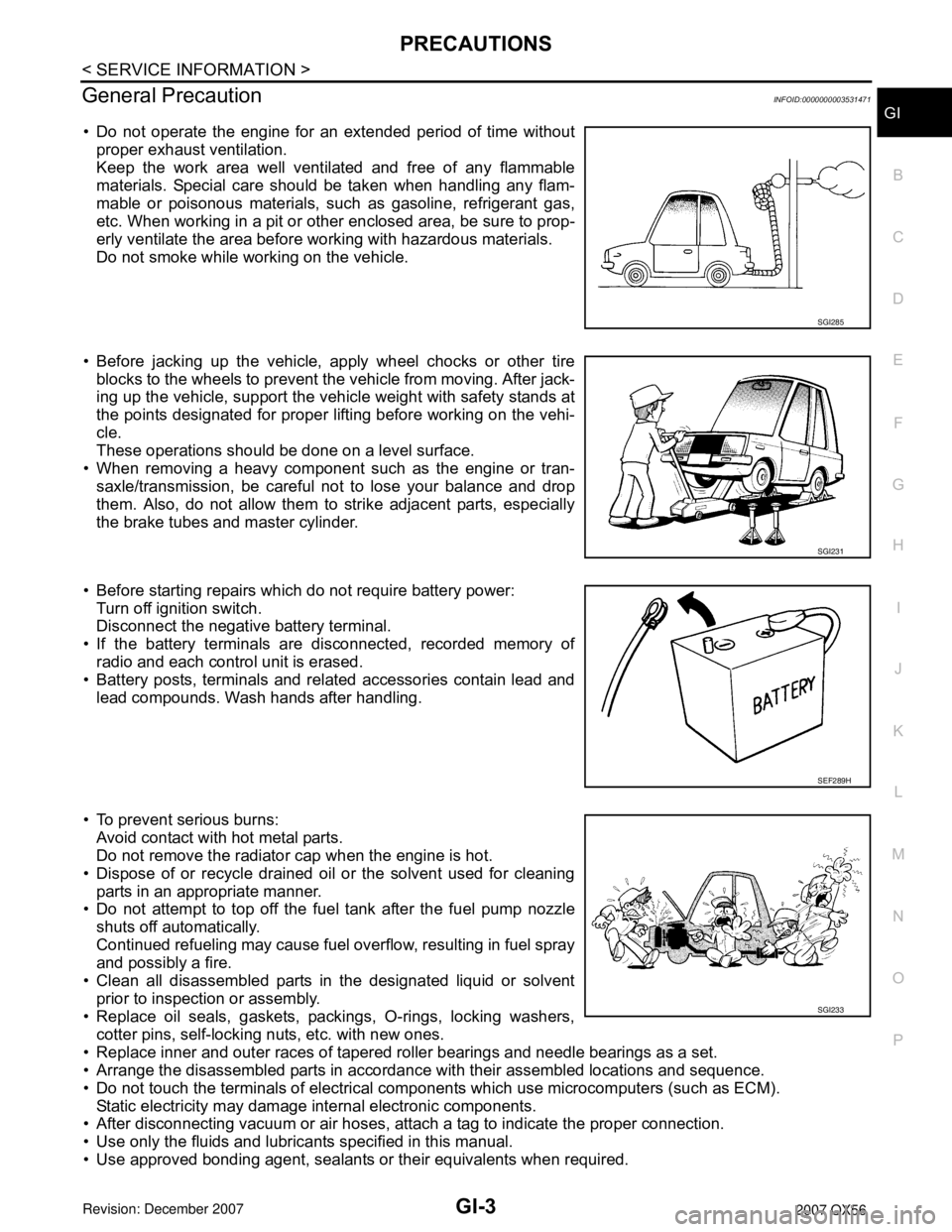
• Do not operate the engine for an extended period of time without
proper exhaust ventilation.
Keep the work area well ventilated and free of any flammable
materials. Special care should be taken when handling any flam-
mable or poisonous materials, such as gasoline, refrigerant gas,
etc. When working in a pit or other enclosed area, be sure to prop-
erly ventilate the area before working with hazardous materials.
Do not smoke while working on the vehicle.
• Before jacking up the vehicle, apply wheel chocks or other tire
blocks to the wheels to prevent the vehicle from moving. After jack-
ing up the vehicle, support the vehicle weight with safety stands at
the points designated for proper lifting before working on the vehi-
cle.
These operations should be done on a level surface.
• When removing a heavy component such as the engine or tran-
saxle/transmission, be careful not to lose your balance and drop
them. Also, do not allow them to strike adjacent parts, especially
the brake tubes and master cylinder.
• Before starting repairs which do not require battery power:
Turn off ignition switch.
Disconnect the negative battery terminal.
• If the battery terminals are disconnected, recorded memory of
radio and each control unit is erased.
• Battery posts, terminals and related accessories contain lead and
lead compounds. Wash hands after handling.
• To prevent serious burns:
Avoid contact with hot metal parts.
Do not remove the radiator cap when the engine is hot.
• Dispose of or recycle drained oil or the solvent used for cleaning
parts in an appropriate manner.
• Do not attempt to top off the fuel tank after the fuel pump nozzle
shuts off automatically.
Continued refueling may cause fuel overflow, resulting in fuel spray
and possibly a fire.
• Clean all disassembled parts in the designated liquid or solvent
prior to inspection or assembly.
• Replace oil seals, gaskets, packings, O-rings, locking washers,
cotter pins, self-locking nuts, etc. with new ones.
• Replace inner and outer races of tapered roller bearings and needle bearings as a set.
• Arrange the disassembled parts in accordance with their assembled locations and sequence.
• Do not touch the terminals of electrical components which use microcomputers (such as ECM).
Static electricity may damage internal electronic components.
• After disconnecting vacuum or air hoses, attach a tag to indicate the proper connection.
• Use only the fluids and lubricants specified in this manual.
• Use approved bonding agent, sealants or their equivalents when required.
SGI285
SGI231
SEF289H
SGI233
Page 1974 of 3061
GI-8
< SERVICE INFORMATION >
HOW TO USE THIS MANUAL
Contents
INFOID:0000000003531482
•ALPHABETICAL INDEX is provided at the end of this manual so that you can rapidly find the item and page
you are searching for.
•A QUICK REFERENCE INDEX, a black tab (e.g. ) is provided on the first page. You can quickly find the
first page of each section by matching it to the section's black tab.
•THE CONTENTS are listed on the first page of each section.
•THE TITLE is indicated on the upper portion of each page and shows the part or system.
•THE PAGE NUMBER of each section consists of two or three letters which designate the particular section
and a number (e.g. “BR-5”).
•THE SMALL ILLUSTRATIONS show the important steps such as inspection, use of special tools, knacks of
work and hidden or tricky steps which are not shown in the previous large illustrations.
Assembly, inspection and adjustment procedures for the complicated units such as the automatic transaxle
or transmission, etc. are presented in a step-by-step format where necessary.
ComponentINFOID:0000000003531483
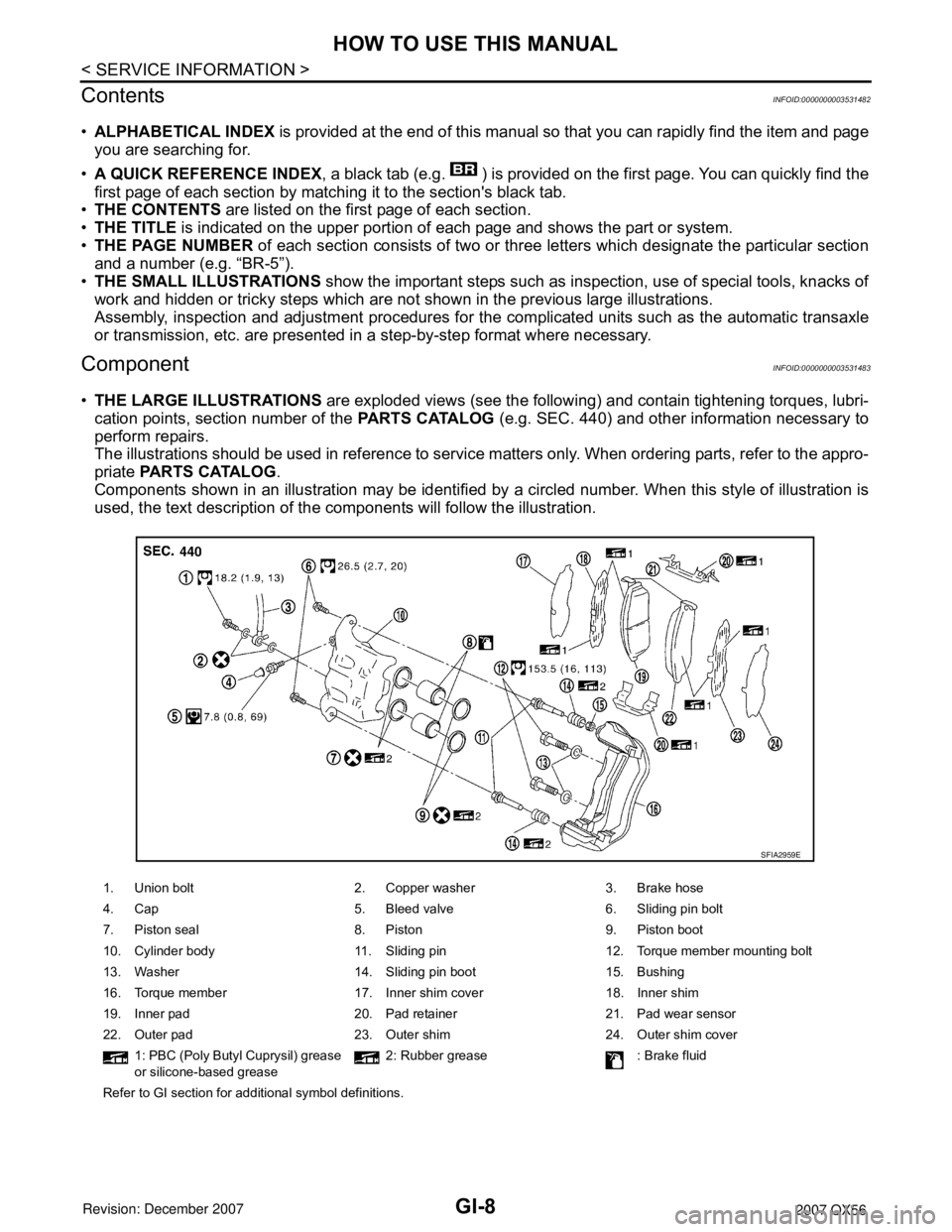
•THE LARGE ILLUSTRATIONS are exploded views (see the following) and contain tightening torques, lubri-
cation points, section number of the PARTS CATALOG (e.g. SEC. 440) and other information necessary to
perform repairs.
The illustrations should be used in reference to service matters only. When ordering parts, refer to the appro-
priate PARTS CATALOG.
Components shown in an illustration may be identified by a circled number. When this style of illustration is
used, the text description of the components will follow the illustration.
1. Union bolt 2. Copper washer 3. Brake hose
4. Cap 5. Bleed valve 6. Sliding pin bolt
7. Piston seal 8. Piston 9. Piston boot
10. Cylinder body 11. Sliding pin 12. Torque member mounting bolt
13. Washer 14. Sliding pin boot 15. Bushing
16. Torque member 17. Inner shim cover 18. Inner shim
19. Inner pad 20. Pad retainer 21. Pad wear sensor
22. Outer pad 23. Outer shim 24. Outer shim cover
1: PBC (Poly Butyl Cuprysil) grease
or silicone-based grease2: Rubber grease : Brake fluid
Refer to GI section for additional symbol definitions.
SFIA2959E
Page 2106 of 3061
IDX-2
ALPHABETICAL INDEX
Numerics
2-4WD shift solenoid valve ..... TF-93
, TF-154, TF-167
4WD - Wiring diagram ....................................... TF-24
4WD shift switch ................................................ TF-65
4WD solenoid valve ................ TF-89, TF-154, TF-167
4WD system description .................................... TF-15
4WD system diagram ........................................ TF-19
A
A/C air flow ...................................................... ATC-30
A/C compressor clutch removal and installation .. ATC-
180
A/C compressor mounting ............................. ATC-179
A/C compressor precaution ............................. ATC-11
A/C compressor special service tool ................ ATC-14
A/C control operation (auto A/C) ...................... ATC-27
A/C diagnostic work flow (auto A/C) .............. ATC-133
A/C evaporator ............................................... ATC-186
A/C HFC134a (R134a) system identification ..... ATC-6
A/C HFC134a (R134a) system precaution ........ ATC-5
A/C HFC134a (R134a) system service procedure ATC-
175
A/C HFC134a (R134a) system service tools ... ATC-14
A/C HFC134a system service equipment precaution ...
ATC-11
A/C lubricant (R134a) ...................................... ATC-22
A/C lubrication oil ............................................. ATC-22
A/C operational check ....................... ATC-56, ATC-58
A/C self-diagnoses (auto A/C) ........ ATC-54, ATC-133
A/C service data specification ........................ ATC-193
A/C trouble diagnoses (auto A/C) .................... ATC-34
A/C, A - Wiring diagram ................................... ATC-42
A/T fluid checking ...................... AT-12, AT-51, MA-22
A/T fluid cooler cleaning .................................... AT-14
A/T fluid replacement ............................. AT-12, MA-24
A/T fluid temperature sensor ........................... AT-123
A/T IND - Wiring diagram .................................... DI-36
A/T indicator ........................................................ DI-36
A/T shift lock system ........................................ AT-216
A/T trouble diagnoses ........................................ AT-42
ABS - Wiring diagram ..................................... BRC-16
ABS (anti-lock brake system) ........................... BRC-7
Accelerator control system ............................... ACC-3
Accelerator pedal position (APP) sensor . EC-608, EC-
614, EC-628
Accelerator pedal released position learning ..... EC-80
AF1B1-Wiring diagram EC-242, EC-250, EC-258, EC-
267, EC-638
AF1B2-Wiring diagram EC-244, EC-252, EC-260, EC-
269, EC-640
AF1HB1-Wiring diagram .................................. EC-175
AF1HB2-Wiring diagram .................................. EC-177
Aiming adjustment .................................. LT-23, LT-61
Air bag .............................................................. SRS-3
Air bag precautions .............................................. AV-4
Air cleaner and air duct ..................................... EM-15
Air cleaner filter replacement ................ EM-16, MA-16
Air conditioner cut control ................................. EC-29
Air flow meter - See Mass air flow sensor EC-197, EC-
206
Air fuel ratio sensor 1 .. EC-239, EC-248, EC-256, EC-
264, EC-636
Air fuel ratio sensor 1 heater ........................... EC-174
Air mix. door motor .......................................... ATC-69
Ambient sensor ............................. ATC-138, ATC-149
Angular tightening application ............................. EM-4
Antenna .............................................................. AV-58
APPS1 - Wiring diagram ................................. EC-610
APPS2 - Wiring diagram ................................. EC-616
APPS3 - Wiring diagram ................................. EC-630
ASC/BS - Wiring diagram ............................... EC-574
ASC/SW - Wiring diagram .............................. EC-557
ASCBOF - Wiring diagram .............................. EC-648
ASCD ................................................................ EC-30
ASCD (automatic speed control device) ........... ACS-3
ASCD brake switch ........................... EC-572, EC-647
ASCD indicator lamp ....................................... EC-654
ASCD steering switch ..................................... EC-555
ASCIND - Wiring diagram ............................... EC-655
ATP switch ............................ TF-106, TF-109, TF-114
Audio .................................................................... AV-6
AUDIO - Wiring diagram .................................... AV-11
AUT/DP - Wiring diagram .................................. SE-16
Auto air conditioner - Wiring diagram .............. ATC-42
Auto anti-dazzling inside mirror ........... GW-69, GW-70
Autolamp ............................................................ LT-38
Automatic amplifier ......................................... ATC-59
Automatic drive positioner .................................. SE-11
Automatic transmission number .......................... GI-50
B
Back door ........................................................... BL-88
Back door trim ..................................................... EI-32
Back sonar .......................................................... DI-50
BACK/L - Wiring diagram ................................... LT-87
Back-up lamp ..................................................... LT-87
Ball joint (front) ................................................ FSU-15
Basic inspection ................................................ EC-73
Battery ................................................................. SC-4
Battery current sensor . EC-520, EC-527, EC-534, EC-
541
Battery/Starting/Charging System Tester SC-6, SC-12,
SC-20
BCM (Body control module) ................ BCS-3, AV-106
Block heater ...................................................... EM-78
Blower motor ................................... ATC-93, ATC-153
Body alignment ................................................ BL-164
Body component parts ..................................... BL-151
Body construction ............................................ BL-163
Body exterior paint color .................................. BL-150
Body mounting ................................................. BL-149
Body repair ....................................................... BL-150
Body sealing .................................................... BL-160
Bose speaker amp. .............................................. AV-8
Brake booster .................................................... BR-17
Page 2107 of 3061
IDX-3
A
C
D
E
F
G
H
I
J
K
L B
IDX
ALPHABETICAL INDEX
Brake fluid level ................................................. MA-28
Brake hydraulic line ........................................... BR-12
Brake inspection ................................................ MA-28
Brake lines and cables inspection ..................... MA-28
Brake master cylinder ....................................... BR-15
Brake switch ...................................... EC-572, EC-584
BRK/SW - Wiring diagram ............................... EC-585
Bulb specifications ........................................... LT-148
Bumper, front ...................................................... EI-13
Bumper, rear ....................................................... EI-15
C
Cabin air filter .................................................... MA-21
Camshaft ........................................................... EM-46
Camshaft inspection .......................................... EM-49
Camshaft position sensor (PHASE) ................ EC-369
CAN - Wiring diagram .............. EC-157, AT-93, AT-94
CAN communication EC-32, EC-156, EC-159, TF-112,
RSU-6
Canister-See EVAP canister ............................. EC-36
Center case (Transfer) ....................... TF-154, TF-167
CHARGE - Wiring diagram ............................... SC-19
Charging system ............................................... SC-17
Chassis and body maintenance ........................ MA-21
Chassis and body maintenanceSchedule 1 ........ MA-8
Chassis and body maintenanceSchedule 2 ...... MA-10
CHIME - Wiring diagram ..................................... DI-41
Circuit breaker ................................................... PG-17
Clock ................................................................... DI-61
CLOCK - Wiring diagram .................................... DI-61
Closed loop control ............................. EC-26, EC-501
Closed loop control (Bank 1) ........................... EC-501
Closed loop control (Bank 2) ........................... EC-501
Clutch drum (Transfer) ....................... TF-154, TF-167
Clutch pressure switch (Transfer) ...... TF-154, TF-167
Coil spring (front) ............................................. FSU-10
Collision diagnosis .......................................... SRS-53
Combination lamp, front, removal and installation . LT-
25
Combination lamp, rear, removal and installation .. LT-
101
Combination meter ................................................ DI-5
Combination switch ............................................ LT-79
COMBSW - Wiring diagram ............................... LT-79
COMM - Wiring diagram ................................... AV-94
COMPAS - Wiring diagram ................................. DI-24
Compass ............................................................. DI-23
Component Location (auto A/C) ...................... ATC-38
Compressor clutch removal and installation . ATC-180
Compressor mounting ................................... ATC-179
Compressor precaution ................................... ATC-11
Compressor special service tool ..................... ATC-14
Condenser ..................................................... ATC-184
Connecting rod .................................................. EM-96
Connecting rod bearing clearance .................... EM-96
Connecting rod bushing clearance .................... EM-96
Console box - See Instrument panel ................... IP-10
CONSULT for VDC ......................................... BRC-27
CONSULT general information ........................... GI-37
CONSULT-II for engine ................................... EC-118
Control units (terminal arrangement) ................. PG-71
Control valve (A/T) ............................................. AT-36
Control valve (Transfer) ...................... TF-154, TF-167
Converter housing installation ............ AT-240, AT-244
COOL/F - Wiring diagram ................................ EC-507
Coolant mixture ratio ......................................... MA-12
Coolant replacement ............................ CO-10, MA-13
Cooling circuit (engine) ........................................ CO-8
Cooling fan ........................................................ CO-17
Cooling fan control ........................................... EC-504
Cooling fan motor ............................................ EC-513
Cooling unit (A/C evaporator) ....... ATC-157, ATC-186
Corrosion protection ......................................... BL-157
Crankcase ventilation system - See Positive crankcase
ventilation .......................................................... EC-46
Crankshaft ......................................................... EM-79
Crankshaft position sensor (POS) ................... EC-362
Crash zone sensor .......................................... SRS-48
CUR/SE - Wiring diagram ... EC-522, EC-529, EC-536,
EC-543
Cylinder block .................................................... EM-78
Cylinder block boring ......................................... EM-99
D
D/LOCK - Wiring diagram ................................... BL-19
Data link connector for Consult ......... EC-120, EC-132
Daytime light system .......................................... LT-27
Daytime running light - See Daytime light system .. LT-
27
DEF - Wiring diagram ....................................... GW-74
Diagnosis sensor unit ...................................... SRS-51
Diagnostic trouble code (DTC) for OBD system . EC-9,
EC-54
Diagnostic trouble code (DTC) inspection priority chart
EC-91
Differential carrier assembly ............................ RFD-15
Differential gear oil replacement ........................ MA-26
Dimensions ......................................................... GI-51
Direct clutch solenoid valve ................ AT-143, AT-145
Display and amp.assembly .............................. ATC-59
Display Control Unit ........................................... AV-83
Display Unit ....................................................... AV-83
Dome light - See Interior lamp .......................... LT-110
Door glass .......................................... GW-62, GW-65
Door lock .......................................................... BL-121
Door mirror lamp ............................................... LT-110
Door trim .............................................................. EI-32
Door, front ........................................... BL-117, GW-62
Door, rear ........................................... BL-117, GW-65
Drive belt ........................................................... EM-13
Drive chain (Transfer) ......................... TF-149, TF-176
Drive pinion diff. inspection .............................. RFD-18
Drive shaft (rear) ................................................ RAX-7
Driver air bag ................................................... SRS-39
DTC work support ............................................ EC-128
DTRL - Wiring diagram ....................................... LT-31
Page 2108 of 3061
IDX-4
ALPHABETICAL INDEX
Duct and grilles .............................................. ATC-170
DVD - Wiring Diagram ....................................... AV-75
DVD Entertainment System ............................... AV-72
DVD Player ........................................................ AV-73
E
ECM input/output signal ..................... EC-109
, EC-133
ECM power supply ............................. EC-150, EC-475
ECM relay ........................................................ EC-150
ECM/PW - Wiring diagram ............................... EC-476
ECTS - Wiring diagram .................................... EC-220
Electric sunroof .................................................. RF-10
Electric throttle control actuator ......... EC-595, EC-606
Electrical load signal circuit .............................. EC-657
Electrical units location ...................................... PG-65
Electronic ignition (EI) system ........................... EC-27
Engine control circuit diagram ......................... EC-107
Engine control component parts location ........... EC-98
Engine control module (ECM) .......................... EC-479
Engine control system diagram ......................... EC-24
Engine coolant .................................................. CO-10
Engine coolant temperature sensor (ECTS) ... EC-218,
EC-231
Engine fail-safe system ...................................... EC-93
Engine oil ............................................................. LU-8
Engine oil filter replacement ............................. MA-17
Engine oil precautions .......................................... GI-7
Engine oil replacement ..................................... MA-17
Engine removal ................................................. EM-74
Engine room cover ............................................ EM-12
Engine serial number .......................................... GI-50
ETC1 - Wiring diagram .................................... EC-596
ETC2 - Wiring diagram .................................... EC-591
ETC3 - Wiring diagram .................................... EC-602
EVAP canister .................................................... EC-36
EVAP canister purge volume control solenoid valve ....
EC-395
, EC-403
EVAP canister vent control valve ....... EC-410, EC-417
EVAP control system (small leak) diagnosis .. EC-387,
EC-441
, EC-449
EVAP control system pressure sensor .... EC-424, EC-
427, EC-433
EVAP control system purge flow monitoring diagnosis
EC-382
EVAP vapor lines inspection ............................. MA-20
Evaporative emission (EVAP) system ............... EC-33
Evaporator ..................................................... ATC-186
Exhaust manifold .............................................. EM-21
Exhaust system ................................................... EX-3
Exhaust system inspection .................................. EX-3
Expansion valve ............................................. ATC-188
F
F/FOG - Wiring diagram ..................................... LT-56
F/PUMP - Wiring diagram ................................ EC-666
Final drive pre-inspection ................................. FFD-15
Final drive removal and installation .. FFD-12, RFD-13
Flow charts .......................................................... GI-27
Fluid temperature sensor (A/T) ........................ AT-123
Fluids ................................................................ MA-11
Fluorescent leak detector .............................. ATC-189
Fog lamp, front ................................................... LT-54
Fog lamp, front, removal and installation ........... LT-62
Foot lamp ......................................................... LT-111
Freeze frame data ............................... EC-55, EC-121
Front brake solenoid valve ................. AT-139, AT-141
Front bumper ...................................................... EI-13
Front case (Transfer) .......................... TF-149, TF-176
Front combination lamp removal and installation LT-25
Front door ............................. BL-117, BL-121, GW-62
Front Door Trim ................................................... EI-32
Front drive shaft (Transfer) ................. TF-149, TF-176
Front fog lamp .................................................... LT-54
Front fog lamp removal and installation ............. LT-62
Front passenger air bag .................................. SRS-43
Front seat ........................................................... SE-89
Front seat belt ...................................................... SB-3
Front seat belt pre-tensioner ............... SRS-3, SRS-50
Front washer ...................................................... WW-4
Front wiper ......................................................... WW-4
FTS - Wiring diagram ....................................... AT-124
FTTS - Wiring diagram ...................... EC-334, EC-339
Fuel cut control (at no load high engine speed) EC-28
Fuel filter replacement ......................................... FL-5
Fuel gauge ............................................................ DI-5
Fuel injection system (Bank 1) .......... EC-311, EC-322
Fuel injection system (Bank 2) .......... EC-311, EC-322
Fuel injector .................................................... EC-659
Fuel injector and fuel tube ................................. EM-31
Fuel level sensor ................. EC-458, EC-460, EC-462
Fuel line inspection .............................................. FL-4
Fuel precautions ................................................... GI-5
Fuel pressure check .......................................... EC-82
Fuel pressure release ....................................... EC-82
Fuel pump ....................................................... EC-665
Fuel pump and gauge .......................................... FL-5
Fuel system .......................................................... FL-4
Fuel tank ............................................................ FL-10
Fuel tank temperature sensor ........... EC-332, EC-338
Fuel tank vacuum relief valve ........................... EC-36
FUELB1 - Wiring diagram ................. EC-313, EC-324
FUELB2 - Wiring diagram ................. EC-315, EC-326
Fuse ...................................................... PG-17, PG-77
Fuse and fusible link box .................................. PG-77
Fuse block ......................................................... PG-76
Fusible link ............................................ PG-17, PG-77
G
Garage jack and safety stand ............................. GI-42
Gauges ................................................................. DI-5
Generator .......................................................... SC-17
Generic scan tool (GST) ................................. EC-131
Glass ...................................... GW-11, GW-62, GW-65
Glove box lamp ................................................ LT-131
GPS antenna ..................................................... AV-82