Page 1175 of 3061

EC-92
< SERVICE INFORMATION >
TROUBLE DIAGNOSIS
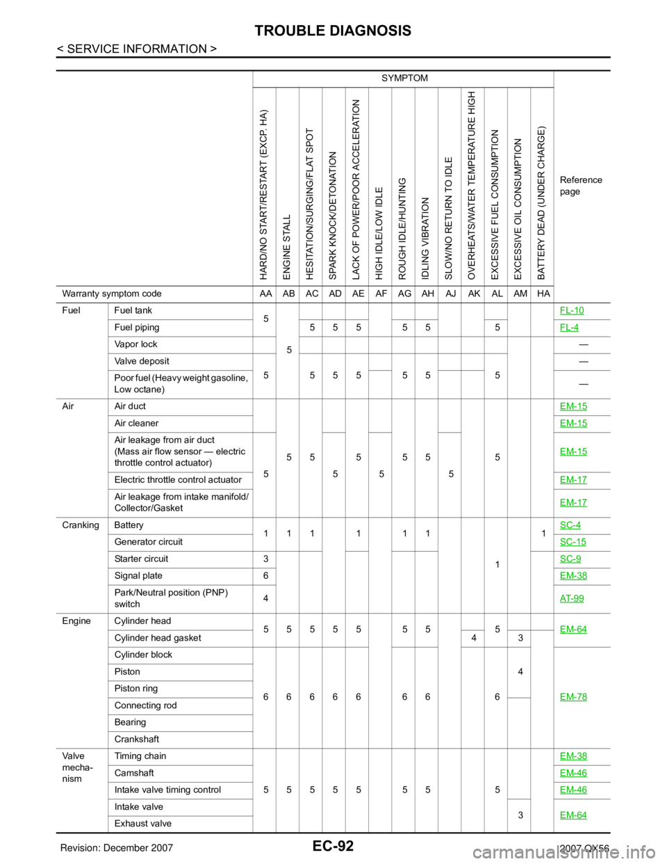
SYMPTOM
Reference
page
HARD/NO START/RESTART (EXCP. HA)
ENGINE STALL
HESITATION/SURGING/FLAT SPOT
SPARK KNOCK/DETONATION
LACK OF POWER/POOR ACCELERATION
HIGH IDLE/LOW IDLE
ROUGH IDLE/HUNTING
IDLING VIBRATION
SLOW/NO RETURN TO IDLE
OVERHEATS/WATER TEMPERATURE HIGH
EXCESSIVE FUEL CONSUMPTION
EXCESSIVE OIL CONSUMPTION
BATTERY DEAD (UNDER CHARGE)
Warranty symptom code AA AB AC AD AE AF AG AH AJ AK AL AM HA
Fuel Fuel tank
5
5FL-10
Fuel piping 5 5 5 5 5 5FL-4
Va p o r l o c k—
Valve deposit
5 555 55 5—
Poor fuel (Heavy weight gasoline,
Low octane)—
Air Air duct
55555 5EM-15
Air cleanerEM-15
Air leakage from air duct
(Mass air flow sensor — electric
throttle control actuator)
5555EM-15
Electric throttle control actuatorEM-17
Air leakage from intake manifold/
Collector/GasketEM-17
Cranking Battery
111111
11SC-4
Generator circuitSC-15
Starter circuit 3SC-9
Signal plate 6EM-38
Park/Neutral position (PNP)
switch4AT- 9 9
Engine Cylinder head
55555 55 5EM-64
Cylinder head gasket 4 3
Cylinder block
66666 66 64
EM-78
Piston
Piston ring
Connecting rod
Bearing
Crankshaft
Va l v e
mecha-
nismTiming chain
55555 55 5EM-38
CamshaftEM-46
Intake valve timing controlEM-46
Intake valve
3EM-64
Exhaust valve
Page 1176 of 3061

TROUBLE DIAGNOSIS
EC-93
< SERVICE INFORMATION >
C
D
E
F
G
H
I
J
K
L
MA
EC
N
P O
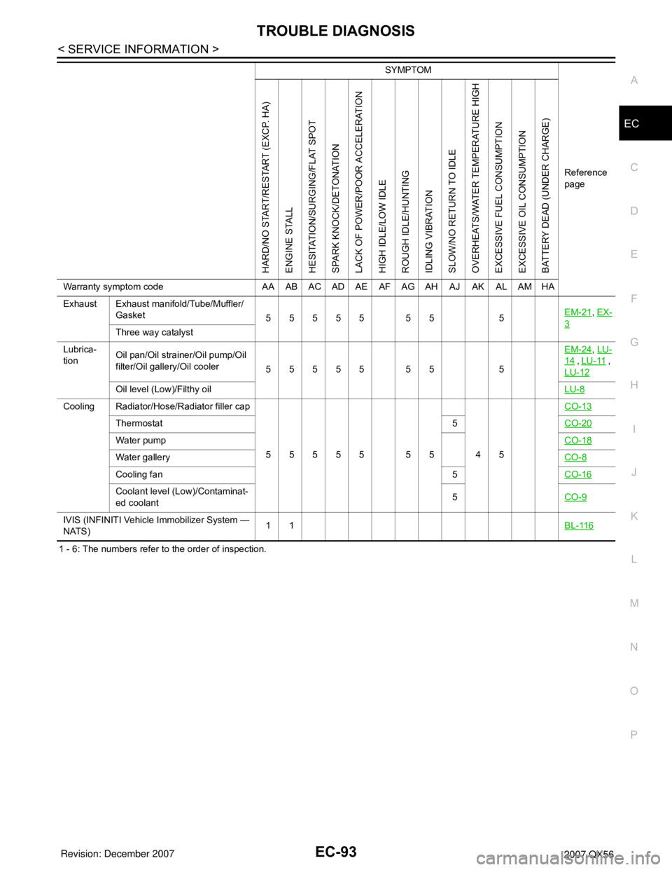
1 - 6: The numbers refer to the order of inspection.Exhaust Exhaust manifold/Tube/Muffler/
Gasket
55555 55 5EM-21
, EX-
3Three way catalyst
Lubrica-
tionOil pan/Oil strainer/Oil pump/Oil
filter/Oil gallery/Oil cooler
55555 55 5EM-24
, LU-
14 , LU-11 ,
LU-12
Oil level (Low)/Filthy oilLU-8
Cooling Radiator/Hose/Radiator filler cap
55555 55 45CO-13
Thermostat 5CO-20
Water pumpCO-18
Water galleryCO-8
Cooling fan 5CO-16
Coolant level (Low)/Contaminat-
ed coolant5CO-9
IVIS (INFINITI Vehicle Immobilizer System —
NATS)11BL-116
SYMPTOM
Reference
page
HARD/NO START/RESTART (EXCP. HA)
ENGINE STALL
HESITATION/SURGING/FLAT SPOT
SPARK KNOCK/DETONATION
LACK OF POWER/POOR ACCELERATION
HIGH IDLE/LOW IDLE
ROUGH IDLE/HUNTING
IDLING VIBRATION
SLOW/NO RETURN TO IDLE
OVERHEATS/WATER TEMPERATURE HIGH
EXCESSIVE FUEL CONSUMPTION
EXCESSIVE OIL CONSUMPTION
BATTERY DEAD (UNDER CHARGE)
Warranty symptom code AA AB AC AD AE AF AG AH AJ AK AL AM HA
Page 1177 of 3061

EC-94
< SERVICE INFORMATION >
TROUBLE DIAGNOSIS
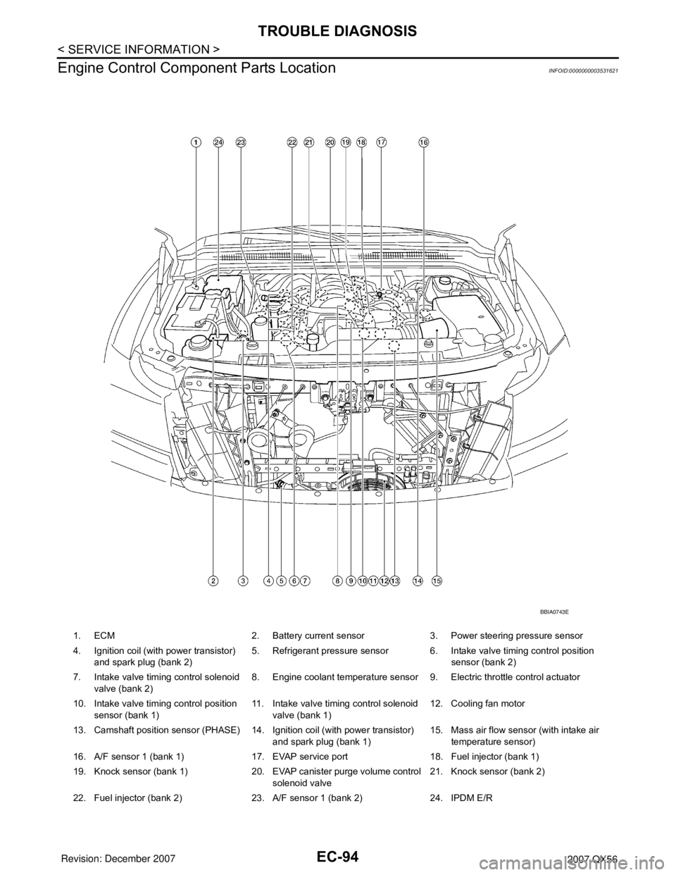
Engine Control Component Parts Location
INFOID:0000000003531621
1. ECM 2. Battery current sensor 3. Power steering pressure sensor
4. Ignition coil (with power transistor)
and spark plug (bank 2)5. Refrigerant pressure sensor 6. Intake valve timing control position
sensor (bank 2)
7. Intake valve timing control solenoid
valve (bank 2)8. Engine coolant temperature sensor 9. Electric throttle control actuator
10. Intake valve timing control position
sensor (bank 1)11. Intake valve timing control solenoid
valve (bank 1)12. Cooling fan motor
13. Camshaft position sensor (PHASE) 14. Ignition coil (with power transistor)
and spark plug (bank 1)15. Mass air flow sensor (with intake air
temperature sensor)
16. A/F sensor 1 (bank 1) 17. EVAP service port 18. Fuel injector (bank 1)
19. Knock sensor (bank 1) 20. EVAP canister purge volume control
solenoid valve21. Knock sensor (bank 2)
22. Fuel injector (bank 2) 23. A/F sensor 1 (bank 2) 24. IPDM E/R
BBIA0743E
Page 1179 of 3061
EC-96
< SERVICE INFORMATION >
TROUBLE DIAGNOSIS
1. EVAP canister purge volume control
solenoid valve (view with engine
cover removed)2. EVAP service port (view with engine
cover removed)3. Crankshaft position sensor (POS)
(view from under the vehicle)
4. Engine oil pan (view from under the
vehicle)5. Condenser-1 6. Brake fluid reservoir
7. EVAP canister (view with fuel tank
removed)8. EVAP control system pressure sen-
sor (view with fuel tank removed)9. EVAP canister vent control valve
(view with fuel tank removed)
10. Rear suspension member (view with
fuel tank removed)11. Refrigerant pressure sensor (view
with hood open)12. Intake valve timing control position
sensor (bank 2) (view with engine
cover and intake air duct removed)
BBIA0783E
Page 1188 of 3061
TROUBLE DIAGNOSIS
EC-105
< SERVICE INFORMATION >
C
D
E
F
G
H
I
J
K
L
MA
EC
N
P O
13 OCrankshaft position sensor
(POS)[Engine is running]
•Warm-up condition
• Idle speed
NOTE:
The pulse cycle changes depending on rpm at
idleApproximately 10V
[Engine is running]
• Engine speed: 2,000 rpmApproximately 10V
14 YCamshaft position sensor
(PHASE)[Engine is running]
•Warm-up condition
• Idle speed
NOTE:
The pulse cycle changes depending on rpm at
idle1.0 - 4.0V
[Engine is running]
• Engine speed: 2,000 rpm1.0 - 4.0V
15 W Knock sensor (bank 1)[Engine is running]
• Idle speedApproximately 2.5V
16 G/L A/F sensor 1 (bank 1)[Engine is running]
•Warm-up condition
• Engine speed: 2,000 rpmApproximately 1.8V
Output voltage varies with air fuel
ratio. TER-
MI-
NAL
NO.WIRE
COLORITEM CONDITION DATA (DC Voltage)PBIB1041E
PBIB1042E
PBIB1039E
PBIB1040E
Page 1189 of 3061
![INFINITI QX56 2007 Factory Service Manual EC-106
< SERVICE INFORMATION >
TROUBLE DIAGNOSIS
21
22
23
44O/L
BR
GR/W
OFuel injector No. 5
Fuel injector No. 3
Fuel injector No. 1
Fuel injector No. 7[Engine is running]
•Warm-up condition
• Idl INFINITI QX56 2007 Factory Service Manual EC-106
< SERVICE INFORMATION >
TROUBLE DIAGNOSIS
21
22
23
44O/L
BR
GR/W
OFuel injector No. 5
Fuel injector No. 3
Fuel injector No. 1
Fuel injector No. 7[Engine is running]
•Warm-up condition
• Idl](/manual-img/42/57029/w960_57029-1188.png)
EC-106
< SERVICE INFORMATION >
TROUBLE DIAGNOSIS
21
22
23
44O/L
BR
GR/W
OFuel injector No. 5
Fuel injector No. 3
Fuel injector No. 1
Fuel injector No. 7[Engine is running]
•Warm-up condition
• Idle speed
NOTE:
The pulse cycle changes depending on rpm at
idleBATTERY VOLTAGE
(11 - 14V)
[Engine is running]
•Warm-up condition
• Engine speed: 2,000 rpmBATTERY VOLTAGE
(11 - 14V)
24
43GR/G
GR/GA/F sensor 1 heater (bank 2)[Engine is running]
•Warm-up condition
• Idle speed
(More than 140 seconds after starting en-
gine)Approximately 2.9 - 8.8V
25 O/GHeated oxygen sensor 2 heat-
er (bank 2)[Engine is running]
• Engine speed: Below 3,600 rpm after the
following conditions are met.
- Engine: After warming up
- Keeping the engine speed between 3,500
and 4,000 rpm for 1 minute and at idle for 1
minute under no load0 - 1.0V
[Ignition switch: ON]
• Engine: Stopped
[Engine is running]
• Engine speed: Above 3,600 rpmBATTERY VOLTAGE
(11 - 14V)
32 LEVAP control system pres-
sure sensor[Ignition switch: ON]Approximately 1.8 - 4.8V
34 R/B Intake air temperature sensor[Engine is running]Approximately 0 - 4.8V
Output voltage varies with intake
air temperature.
35 BR/R A/F sensor 1 (bank 1)[Engine is running]
•Warm-up condition
• Engine speed: 2,000 rpmApproximately 1.8V
Output voltage varies with air fuel
ratio.
36 W Knock sensor (bank 2)[Engine is running]
• Idle speedApproximately 2.5V TER-
MI-
NAL
NO.WIRE
COLORITEM CONDITION DATA (DC Voltage)SEC984C
SEC985C
PBIA8148J
Page 1190 of 3061
![INFINITI QX56 2007 Factory Service Manual TROUBLE DIAGNOSIS
EC-107
< SERVICE INFORMATION >
C
D
E
F
G
H
I
J
K
L
MA
EC
N
P O
40
41
42
63Y/G
P
L
GFuel injector No. 6
Fuel injector No. 4
Fuel injector No. 2
Fuel injector No. 8[Engine is running] INFINITI QX56 2007 Factory Service Manual TROUBLE DIAGNOSIS
EC-107
< SERVICE INFORMATION >
C
D
E
F
G
H
I
J
K
L
MA
EC
N
P O
40
41
42
63Y/G
P
L
GFuel injector No. 6
Fuel injector No. 4
Fuel injector No. 2
Fuel injector No. 8[Engine is running]](/manual-img/42/57029/w960_57029-1189.png)
TROUBLE DIAGNOSIS
EC-107
< SERVICE INFORMATION >
C
D
E
F
G
H
I
J
K
L
MA
EC
N
P O
40
41
42
63Y/G
P
L
GFuel injector No. 6
Fuel injector No. 4
Fuel injector No. 2
Fuel injector No. 8[Engine is running]
•Warm-up condition
• Idle speed
NOTE:
The pulse cycle changes depending on rpm at
idleBATTERY VOLTAGE
(11 - 14V)
[Engine is running]
•Warm-up condition
• Engine speed: 2,000 rpmBATTERY VOLTAGE
(11 - 14V)
45 L/YEVAP canister purge volume
control solenoid valve[Engine is running]
• Idle speed
• Accelerator pedal: Not depressed even
slightly, after engine startingBATTERY VOLTAGE
(11 - 14V)
[Engine is running]
• Engine speed: About 2,000 rpm (More than
100 seconds after starting engine)BATTERY VOLTAGE
(11 - 14V)
47 YSensor power supply
(Throttle position sensor)[Ignition switch: ON]Approximately 5V
48 SBSensor power supply
(EVAP control system pres-
sure sensor)[Ignition switch: ON]Approximately 5V
49 R/YSensor power supply
(Refrigerant pressure sensor)[Ignition switch: ON]Approximately 5V
50 B Throttle position sensor 1[Ignition switch: ON]
• Engine: Stopped
• Selector lever: D
• Accelerator pedal: Fully releasedMore than 0.36V
[Ignition switch: ON]
• Engine: Stopped
• Selector lever: D
• Accelerator pedal: Fully depressedLess than 4.75V TER-
MI-
NAL
NO.WIRE
COLORITEM CONDITION DATA (DC Voltage)SEC984C
SEC985C
SEC990C
SEC991C
Page 1193 of 3061
![INFINITI QX56 2007 Factory Service Manual EC-110
< SERVICE INFORMATION >
TROUBLE DIAGNOSIS
98 G/RAccelerator pedal position
sensor 2[Ignition switch: ON]
• Engine: Stopped
• Accelerator pedal: Fully released0.25 - 0.50V
[Ignition switch: INFINITI QX56 2007 Factory Service Manual EC-110
< SERVICE INFORMATION >
TROUBLE DIAGNOSIS
98 G/RAccelerator pedal position
sensor 2[Ignition switch: ON]
• Engine: Stopped
• Accelerator pedal: Fully released0.25 - 0.50V
[Ignition switch:](/manual-img/42/57029/w960_57029-1192.png)
EC-110
< SERVICE INFORMATION >
TROUBLE DIAGNOSIS
98 G/RAccelerator pedal position
sensor 2[Ignition switch: ON]
• Engine: Stopped
• Accelerator pedal: Fully released0.25 - 0.50V
[Ignition switch: ON]
• Engine: Stopped
• Accelerator pedal: Fully depressed2.0 - 2.5V
99 G/YASCD steering switch
(Models with ICC system)[Ignition switch: ON]
• ICC steering switch: OFFApproximately 4.3V
[Ignition switch: ON]
• MAIN switch: PressedApproximately 0V
[Ignition switch: ON]
• CANCEL switch: PressedApproximately 1.3V
[Ignition switch: ON]
• RESUME/ACCELERATE switch: PressedApproximately 3.7V
[Ignition switch: ON]
• SET/COAST switch: PressedApproximately 3V
[Ignition switch: ON]
• DISTANCE switch: PressedApproximately 2.2V
99 G/YASCD steering switch
(Models with ASCD system)[Ignition switch: ON]
• ASCD steering switch: OFFApproximately 4V
[Ignition switch: ON]
• MAIN switch: PressedApproximately 0V
[Ignition switch: ON]
• CANCEL switch: PressedApproximately 1V
[Ignition switch: ON]
• RESUME/ACCELERATE switch: PressedApproximately 3V
[Ignition switch: ON]
• SET/COAST switch: PressedApproximately 2V
101 R/W Stop lamp switch[Ignition switch: OFF]
• Brake pedal: Fully releasedApproximately 0V
[Ignition switch: OFF]
• Brake pedal: Slightly depressedBATTERY VOLTAGE
(11 - 14V)
102 GR/R PNP switch[Ignition switch: ON]
• Selector lever: P or NApproximately 0V
[Ignition switch: ON]
• Except the above gear positionBATTERY VOLTAGE
(11 - 14V)
104 O Throttle control motor relay[Ignition switch: OFF]BATTERY VOLTAGE
(11 - 14V)
[Ignition switch: ON]0 - 1.0V
106 BR/WAccelerator pedal position
sensor 1[Ignition switch: ON]
• Engine: Stopped
• Accelerator pedal: Fully released0.5 - 1.0V
[Ignition switch: ON]
• Engine: Stopped
• Accelerator pedal: Fully depressed4.2 - 4.8V
107 V/R Fuel tank temperature sensor[Engine is running]Approximately 0 - 4.8V
Output voltage varies with fuel
tank temperature. TER-
MI-
NAL
NO.WIRE
COLORITEM CONDITION DATA (DC Voltage)