Page 486 of 4647

AIR CONDITIONER CONTROL
ATC-35
C
D
E
F
G
H
I
K
L
MA
B
AT C
Revision: 2007 April2007 M35/M45
�When UPPER VENT switch is OFF, UPPER VENT switch indicator turn OFF, and upper ventilator door is
shut.
A/C SWITCH
Compressor is ON or OFF with this switch.
(Pressing the A/C switch when the A/C switch is ON will turn OFF the A/C switch and compressor.)
FAN SWITCHES
The blower speed is manually controlled with this switch. Seven speeds are available for manual control (as
shown on the display screen).
OFF SWITCH
Compressor and blower are OFF, the intake doors and the mode doors are automatically controlled.
REAR WINDOW DEFOGGER SWITCH
When illumination is ON, rear window is defogged.
INTAKE SWITCH
�When intake switch is ON, FRE LED turns ON, and air inlet is fixed to FRE.
�When press intake switch again, REC LED turns ON, and air inlet is fixed to REC.
�When intake switch is pressed for approximately 1.5 seconds or longer, FRE and REC LEDs blink twice.
Then, automatic control mode is entered. Inlet status is displayed by LED even during automatic con-
trolled.
�When FRE LED is turned ON, shifting mode position to D/F or DEF, or when compressor is turned from
ON to OFF, intake switch is automatically turned OFF (fixed to FRE mode). REC mode can be re-entered
by pressing intake switch again, and then compressor is turned ON. (Except D/F or DEF position)
DUAL SWITCH
�When the DUAL switch indicator is illuminated, the driver side and passenger side temperature can each
be set independently.
�When the DUAL switch indicator is not illuminated, the driver side outlet and setting temperature is
applied to both sides.
Control Operation (Rear Control Switch)NJS000G8
AUTO SWITCH
�When pressing AUTO switch, display for turned on AUTO and fan speed is automatically controlled.
�When pressing AUTO switch, air inlet, air outlet, fan speed, and discharge air temperature are automati-
cally controlled.
FAN SWITCH
The blower speed is manually controlled with this switch. Five speeds are available for manual control (as
shown on the display screen).
RJIA4216E
Page 581 of 4647
ATC-130
BLOWER UNIT
Revision: 2007 April2007 M35/M45
Disassembly and AssemblyNJS000IB
1. Intake box (left) 2. In-cabin microfilter 3. Filter cover
4. Intake box (right) 5. Intake door lever 2 6. Intake door motor
7. Intake door link 8. Intake door lever 1 9. Intake lower case
10. Blower motor assembly 11. Motor cover 12. Intake upper case
13. Intake door 1 14. Intake door 2
SJIA1786E
Page 612 of 4647

REFRIGERANT LINES
ATC-161
C
D
E
F
G
H
I
K
L
MA
B
AT C
Revision: 2007 April2007 M35/M45
Removal and Installation of Low-pressure Pipe 1 and High-pressure Pipe 2NJS000HS
REMOVAL
1. Set the temperature control switch (passenger side) at 18°C (60°F), and then disconnect the battery cable
from the negative terminal.
2. Use a refrigerant collecting equipment (for HFC-134a) to discharge the refrigerant.
3. Remove cowl top cover. Refer to EI-18, "
COWL TOP" .
4. Remove mounting bolt from low-pressure flexible hose bracket.
5. Remove high-pressure pipe 1 from vehicle clip.
6. Disconnect one-touch joints.
a. Set a disconnector [high-pressure side (SST: 9253089908), low-
pressure side (SST: 9253089916)] on A/C piping.
b. Slide a disconnector toward vehicle front until it clicks.
c. Slide A/C piping toward vehicle front and disconnect it.
CAUTION:
Cap or wrap the joint of low-pressure flexible hose, low-
pressure pipe 1 and high-pressure pipe 1, 2 with suitable
material such as vinyl tape to avoid the entry of air.
7. Remove instrument passenger lower panel and glove box. Refer
to IP-10, "
INSTRUMENT PANEL ASSEMBLY" .
8. Remove foot grille (right). Refer to ATC-148, "
Removal of Foot Grilles" .
9. Remove air mix door motor (passenger side). Refer to ATC-140, "
AIR MIX DOOR MOTOR" .
10. Remove mode door motor (passenger side). Refer to ATC-139, "
MODE DOOR MOTOR" .
11. Remove main link (right) and max. cool door link (right). Refer to ATC-134, "
HEATER & COOLING UNIT
ASSEMBLY" .
12. Remove mounting screws, and then remove evaporator cover.
RJIA4169E
RJIA4117E
RJIA4170E
Page 957 of 4647
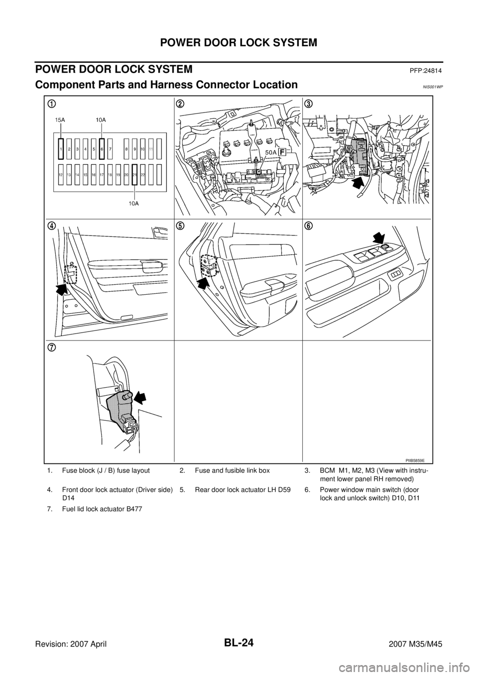
BL-24
POWER DOOR LOCK SYSTEM
Revision: 2007 April2007 M35/M45
POWER DOOR LOCK SYSTEMPFP:24814
Component Parts and Harness Connector LocationNIS001WP
1. Fuse block (J / B) fuse layout 2. Fuse and fusible link box 3. BCM M1, M2, M3 (View with instru-
ment lower panel RH removed)
4. Front door lock actuator (Driver side)
D145. Rear door lock actuator LH D59 6. Power window main switch (door
lock and unlock switch) D10, D11
7. Fuel lid lock actuator B477
PIIB5859E
Page 976 of 4647
INTELLIGENT KEY SYSTEM
BL-43
C
D
E
F
G
H
J
K
L
MA
B
BL
Revision: 2007 April2007 M35/M45
INTELLIGENT KEY SYSTEMPFP:285e2
Component Parts and Harness Connector LocationNIS001X7
1. Fuse block (J/B) fuse layout 2. Fuse and fusible link box 3. BCM M1, M2, M3 (View with instru-
ment lower panel RH removed)
4. IPDM E/R E9 5. Push-button ignition switch M27
(Push switch)6. Combination meter M52
PIIB5860E
Page 1058 of 4647
INTELLIGENT KEY SYSTEM/ENGINE START FUNCTION
BL-125
C
D
E
F
G
H
J
K
L
MA
B
BL
Revision: 2007 April2007 M35/M45
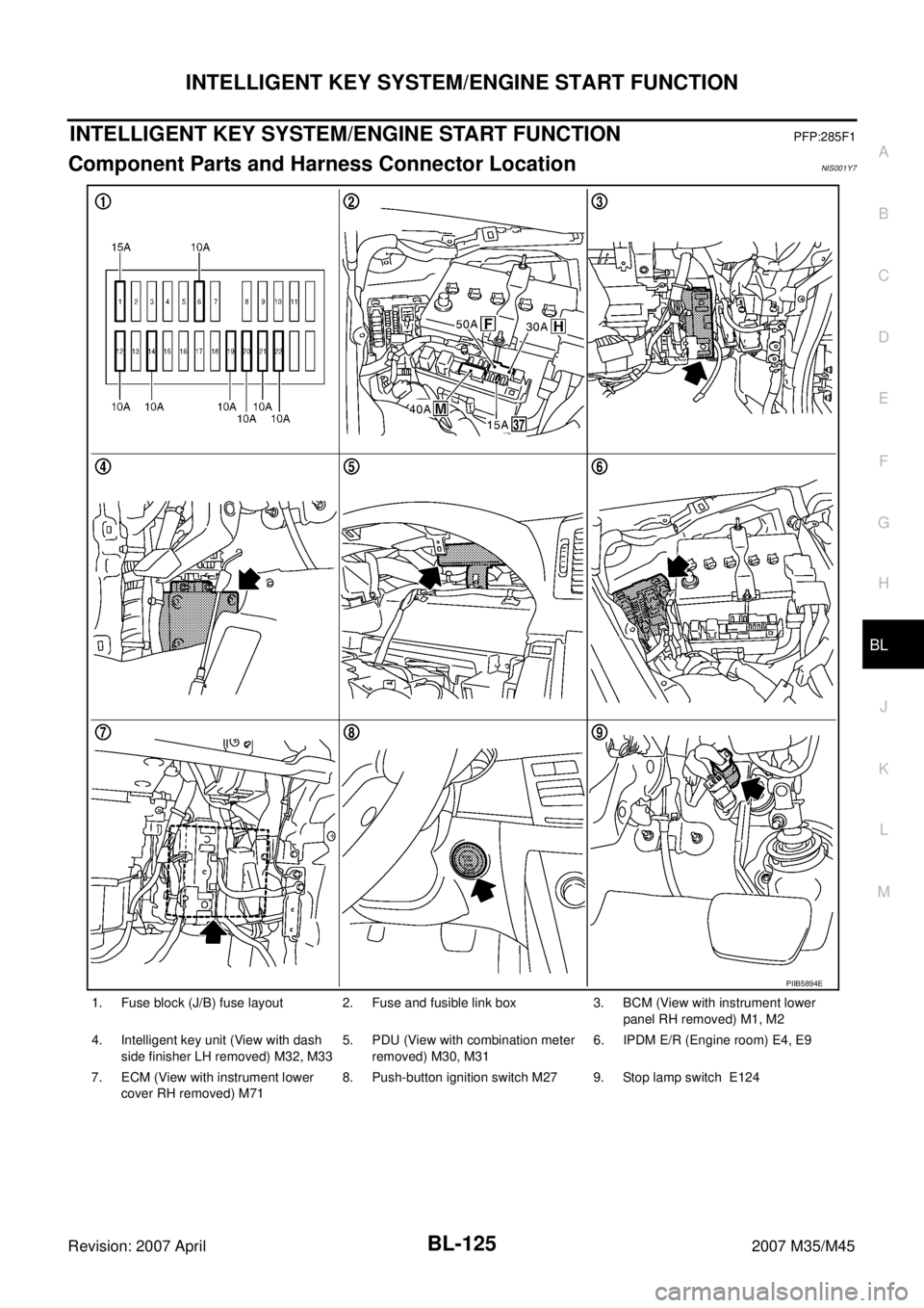
INTELLIGENT KEY SYSTEM/ENGINE START FUNCTIONPFP:285F1
Component Parts and Harness Connector LocationNIS001Y7
1. Fuse block (J/B) fuse layout 2. Fuse and fusible link box 3. BCM (View with instrument lower
panel RH removed) M1, M2
4. Intelligent key unit (View with dash
side finisher LH removed) M32, M335. PDU (View with combination meter
removed) M30, M316. IPDM E/R (Engine room) E4, E9
7. ECM (View with instrument lower
cover RH removed) M718. Push-button ignition switch M27 9. Stop lamp switch E124
PIIB5894E
Page 1140 of 4647
TRUNK LID OPENER
BL-207
C
D
E
F
G
H
J
K
L
MA
B
BL
Revision: 2007 April2007 M35/M45
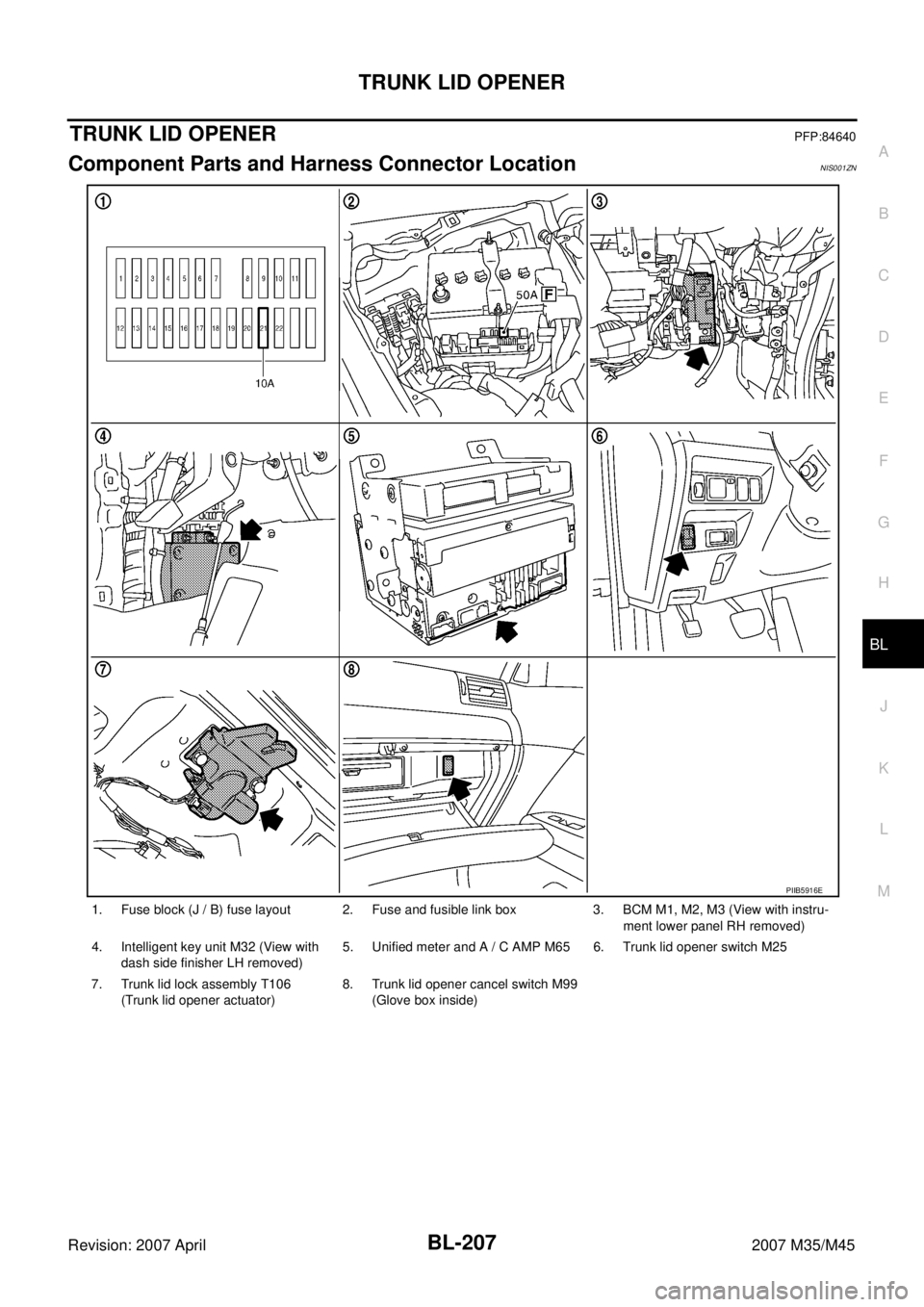
TRUNK LID OPENERPFP:84640
Component Parts and Harness Connector LocationNIS001ZN
1. Fuse block (J / B) fuse layout 2. Fuse and fusible link box 3. BCM M1, M2, M3 (View with instru-
ment lower panel RH removed)
4. Intelligent key unit M32 (View with
dash side finisher LH removed)5. Unified meter and A / C AMP M65 6. Trunk lid opener switch M25
7. Trunk lid lock assembly T106
(Trunk lid opener actuator)8. Trunk lid opener cancel switch M99
(Glove box inside)
PIIB5916E
Page 1151 of 4647
BL-218
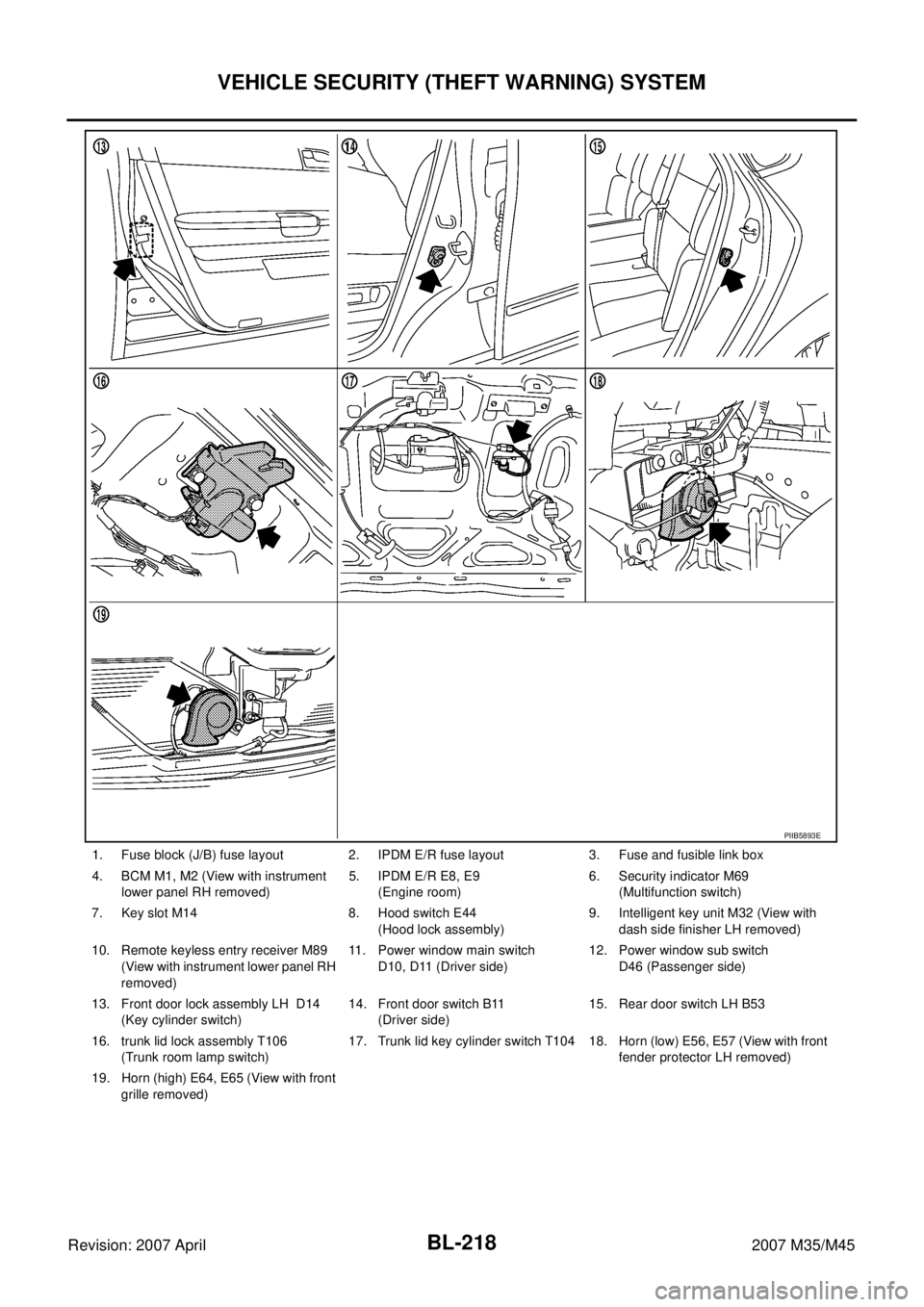
VEHICLE SECURITY (THEFT WARNING) SYSTEM
Revision: 2007 April2007 M35/M45
1. Fuse block (J/B) fuse layout 2. IPDM E/R fuse layout 3. Fuse and fusible link box
4. BCM M1, M2 (View with instrument
lower panel RH removed)5. IPDM E/R E8, E9
(Engine room)6. Security indicator M69
(Multifunction switch)
7. Key slot M14 8. Hood switch E44
(Hood lock assembly)9. Intelligent key unit M32 (View with
dash side finisher LH removed)
10. Remote keyless entry receiver M89
(View with instrument lower panel RH
removed)11. Power window main switch
D10, D11 (Driver side)12. Power window sub switch
D46 (Passenger side)
13. Front door lock assembly LH D14
(Key cylinder switch)14. Front door switch B11
(Driver side)15. Rear door switch LH B53
16. trunk lid lock assembly T106
(Trunk room lamp switch)17. Trunk lid key cylinder switch T104 18. Horn (low) E56, E57 (View with front
fender protector LH removed)
19. Horn (high) E64, E65 (View with front
grille removed)
PIIB5893E