Page 4525 of 4647

TF-36
TROUBLE DIAGNOSIS FOR SYMPTOMS
Revision: 2007 April2007 M35/M45
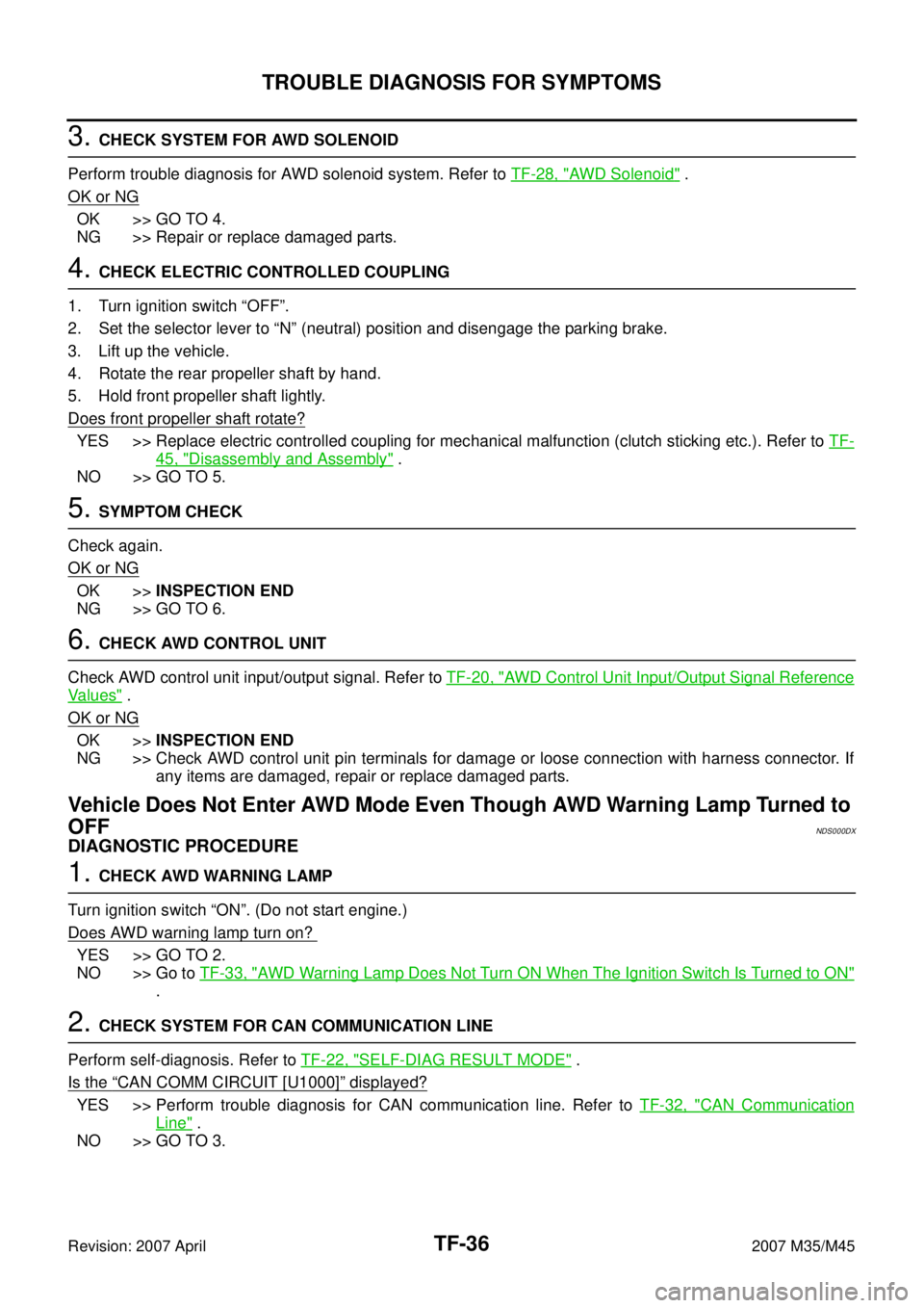
3. CHECK SYSTEM FOR AWD SOLENOID
Perform trouble diagnosis for AWD solenoid system. Refer to TF-28, "
AWD Solenoid" .
OK or NG
OK >> GO TO 4.
NG >> Repair or replace damaged parts.
4. CHECK ELECTRIC CONTROLLED COUPLING
1. Turn ignition switch “OFF”.
2. Set the selector lever to “N” (neutral) position and disengage the parking brake.
3. Lift up the vehicle.
4. Rotate the rear propeller shaft by hand.
5. Hold front propeller shaft lightly.
Does front propeller shaft rotate?
YES >> Replace electric controlled coupling for mechanical malfunction (clutch sticking etc.). Refer to TF-
45, "Disassembly and Assembly" .
NO >> GO TO 5.
5. SYMPTOM CHECK
Check again.
OK or NG
OK >>INSPECTION END
NG >> GO TO 6.
6. CHECK AWD CONTROL UNIT
Check AWD control unit input/output signal. Refer to TF-20, "
AWD Control Unit Input/Output Signal Reference
Va l u e s" .
OK or NG
OK >>INSPECTION END
NG >> Check AWD control unit pin terminals for damage or loose connection with harness connector. If
any items are damaged, repair or replace damaged parts.
Vehicle Does Not Enter AWD Mode Even Though AWD Warning Lamp Turned to
OFF
NDS000DX
DIAGNOSTIC PROCEDURE
1. CHECK AWD WARNING LAMP
Turn ignition switch “ON”. (Do not start engine.)
Does AWD warning lamp turn on?
YES >> GO TO 2.
NO >> Go to TF-33, "
AWD Warning Lamp Does Not Turn ON When The Ignition Switch Is Turned to ON"
.
2. CHECK SYSTEM FOR CAN COMMUNICATION LINE
Perform self-diagnosis. Refer to TF-22, "
SELF-DIAG RESULT MODE" .
Is the
“CAN COMM CIRCUIT [U1000]” displayed?
YES >> Perform trouble diagnosis for CAN communication line. Refer to TF-32, "CAN Communication
Line" .
NO >> GO TO 3.
Page 4527 of 4647
TF-38
TROUBLE DIAGNOSIS FOR SYMPTOMS
Revision: 2007 April2007 M35/M45
2. CHECK INPUT SIGNAL OF TIRE DIAMETER
With CONSULT-II
1. Start engine.
2. Drive at 20 km/h (12 MPH) or more for approx. 200 seconds.
3. Select “DATA MONITOR” mode for “ALL MODE AWD/4WD” with CONSULT-II.
4. Check monitor “DIS-TIRE MONI”.
Display of
“DIS-TIRE MONI”
“0-4mm”>>INSPECTION END
Except for “0-4mm”>>GO TO 3.
3. CHECK AWD CONTROL UNIT
Check AWD control unit input/output signal. Refer to TF-20, "
AWD Control Unit Input/Output Signal Reference
Va l u e s" .
OK or NG
OK >> GO TO 4.
NG >> Check AWD control unit pin terminals for damage or loose connection with harness connector. If
any items are damaged, repair or replace damaged parts.
4. SYMPTOM CHECK
Check again.
OK or NG
OK >>INSPECTION END
NG >> Replace AWD control unit.
SDIA1900E
Page 4533 of 4647

TF-44
TRANSFER ASSEMBLY
Revision: 2007 April2007 M35/M45
TRANSFER ASSEMBLYPFP:33100
Removal and InstallationNDS000E4
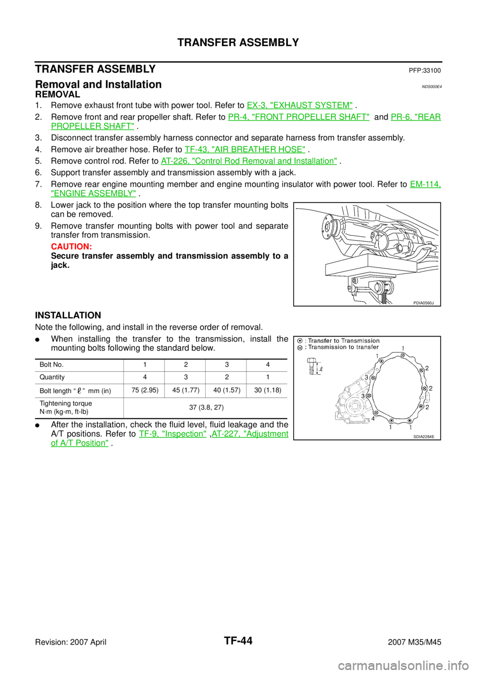
REMOVAL
1. Remove exhaust front tube with power tool. Refer to EX-3, "EXHAUST SYSTEM" .
2. Remove front and rear propeller shaft. Refer to PR-4, "
FRONT PROPELLER SHAFT" and PR-6, "REAR
PROPELLER SHAFT" .
3. Disconnect transfer assembly harness connector and separate harness from transfer assembly.
4. Remove air breather hose. Refer to TF-43, "
AIR BREATHER HOSE" .
5. Remove control rod. Refer to AT- 2 2 6 , "
Control Rod Removal and Installation" .
6. Support transfer assembly and transmission assembly with a jack.
7. Remove rear engine mounting member and engine mounting insulator with power tool. Refer to EM-114,
"ENGINE ASSEMBLY" .
8. Lower jack to the position where the top transfer mounting bolts
can be removed.
9. Remove transfer mounting bolts with power tool and separate
transfer from transmission.
CAUTION:
Secure transfer assembly and transmission assembly to a
jack.
INSTALLATION
Note the following, and install in the reverse order of removal.
�When installing the transfer to the transmission, install the
mounting bolts following the standard below.
�After the installation, check the fluid level, fluid leakage and the
A/T positions. Refer to TF-9, "
Inspection" ,AT- 2 2 7 , "Adjustment
of A/T Position" .
PDIA0560J
Bolt No. 1 2 3 4
Quantity 4 3 2 1
Bolt length “ ” mm (in)75 (2.95) 45 (1.77) 40 (1.57) 30 (1.18)
Tightening torque
N·m (kg-m, ft-lb)37 (3.8, 27)
SDIA2284E
Page 4583 of 4647

WT-34
TROUBLE DIAGNOSIS FOR SYSTEM
Revision: 2007 April2007 M35/M45
Control Unit (EEPROM) MalfunctionNES000KT
MALFUNCTION CODE NO. 54
1. CHECK SELF-DIAGNOSIS RESULTS
1. Turn ignition switch “ON”. (Do not start engine.)
2. Select “SELF-DIAG RESULT” mode for “AIR PRESSURE MONITOR” with CONSULT-II.
3. Touch “ERASE”.
4. Turn ignition switch OFF, and wait at least 10 seconds.
5. Start engine.
6. Perform the self-diagnosis again.
Is the
“CONTROL UNIT (EEPROM) [C1754]” displayed?
YES >> Replace low tire pressure warning control unit. Refer to WT-40, "Low Tire Pressure Warning Con-
trol Unit" .
NO >>INSPECTION END
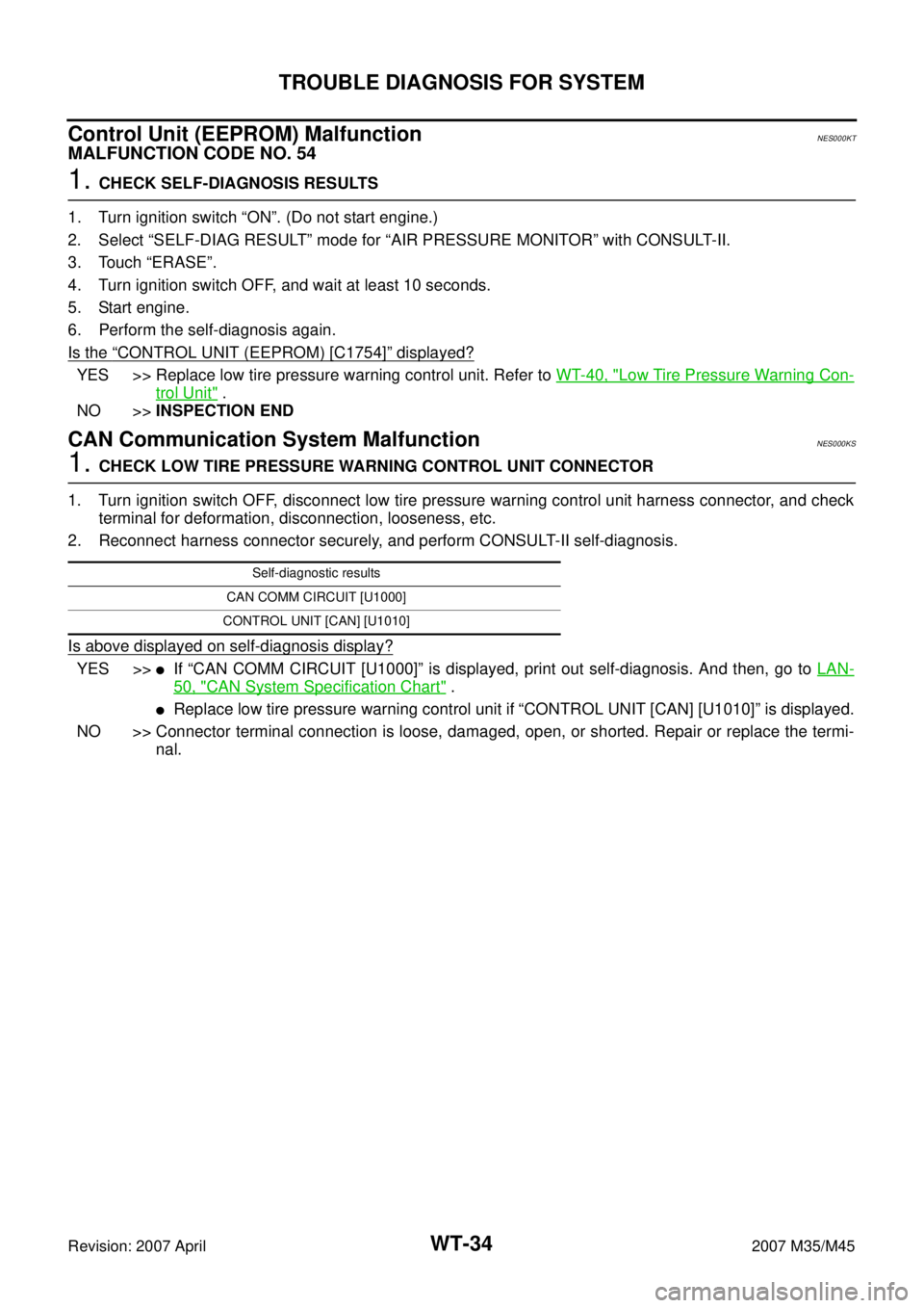
CAN Communication System MalfunctionNES000KS
1. CHECK LOW TIRE PRESSURE WARNING CONTROL UNIT CONNECTOR
1. Turn ignition switch OFF, disconnect low tire pressure warning control unit harness connector, and check
terminal for deformation, disconnection, looseness, etc.
2. Reconnect harness connector securely, and perform CONSULT-II self-diagnosis.
Is above displayed on self-diagnosis display?
YES >>�If “CAN COMM CIRCUIT [U1000]” is displayed, print out self-diagnosis. And then, go to LAN-
50, "CAN System Specification Chart" .
�Replace low tire pressure warning control unit if “CONTROL UNIT [CAN] [U1010]” is displayed.
NO >> Connector terminal connection is loose, damaged, open, or shorted. Repair or replace the termi-
nal.
Self-diagnostic results
CAN COMM CIRCUIT [U1000]
CONTROL UNIT [CAN] [U1010]
Page 4639 of 4647
WW-48
FRONT WIPER AND WASHER SYSTEM
Revision: 2007 April2007 M35/M45
Removal and Installation of Washer TankNKS003X7
: Vehicle front
REMOVAL
1. Remove engine room cover (RH). Refer to EM-15, "Removal and Installation" .
2. Remove clip (A) and pull washer tank inlet (1) out of washer
tank.
3. Remove front bumper. Refer to EI-11, "
Removal and Installation" .
4. Disconnect washer pump connector and wash fluid level sensor connector.
5. Remove washer tank mounting nuts (A) and remove bolt (B).
6. Remove washer tube, and remove washer tank (1) from vehicle.
INSTALLATION
Note the following, and installation is the reverse order of removal.
CAUTION:
After installation, add water up to the upper level of washer tank inlet, and check for water leaks.
SKIB4258E
SKIB4259E
Washer tank mounting nuts : 4.5 N·m (0.46 kg-m, 40 in-lb)
Washer tank mounting bolt : 4.5 N·m (0.46 kg-m, 40 in-lb)