Page 4019 of 4647

PS-38
POWER STEERING OIL PUMP
Revision: 2007 April2007 M35/M45
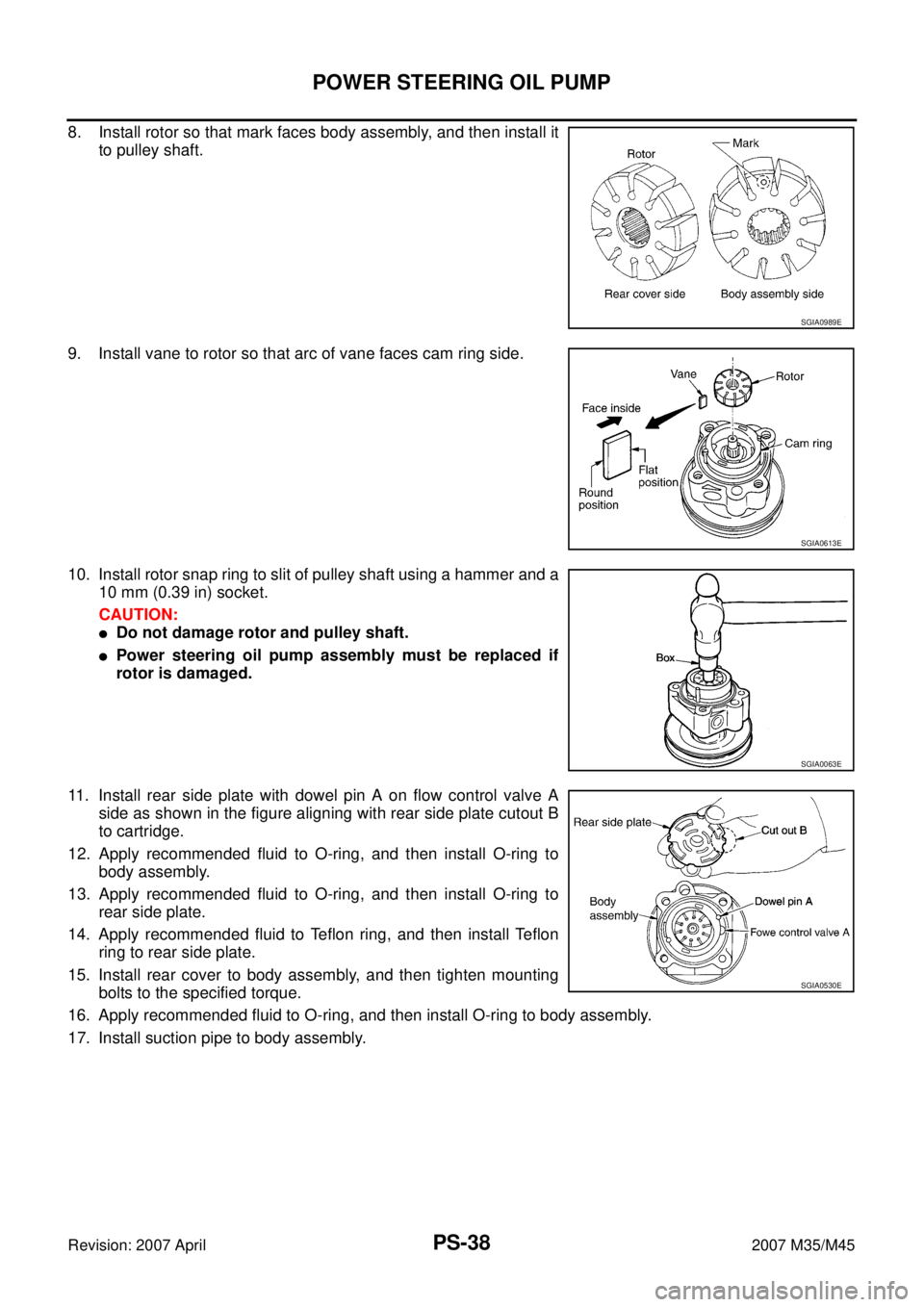
8. Install rotor so that mark faces body assembly, and then install it
to pulley shaft.
9. Install vane to rotor so that arc of vane faces cam ring side.
10. Install rotor snap ring to slit of pulley shaft using a hammer and a
10 mm (0.39 in) socket.
CAUTION:
�Do not damage rotor and pulley shaft.
�Power steering oil pump assembly must be replaced if
rotor is damaged.
11. Install rear side plate with dowel pin A on flow control valve A
side as shown in the figure aligning with rear side plate cutout B
to cartridge.
12. Apply recommended fluid to O-ring, and then install O-ring to
body assembly.
13. Apply recommended fluid to O-ring, and then install O-ring to
rear side plate.
14. Apply recommended fluid to Teflon ring, and then install Teflon
ring to rear side plate.
15. Install rear cover to body assembly, and then tighten mounting
bolts to the specified torque.
16. Apply recommended fluid to O-ring, and then install O-ring to body assembly.
17. Install suction pipe to body assembly.
SGIA0989E
SGIA0613E
SGIA0063E
SGIA0530E
Page 4027 of 4647

PS-46
SERVICE DATA AND SPECIFICATIONS (SDS)
Revision: 2007 April2007 M35/M45
Steering GearNGS000DP
STEERING OUTER SOCKET AND INNER SOCKET
RACK STROKE
RACK SLIDING FORCE
Oil PumpNGS000DR
Steering FluidNGS000DS
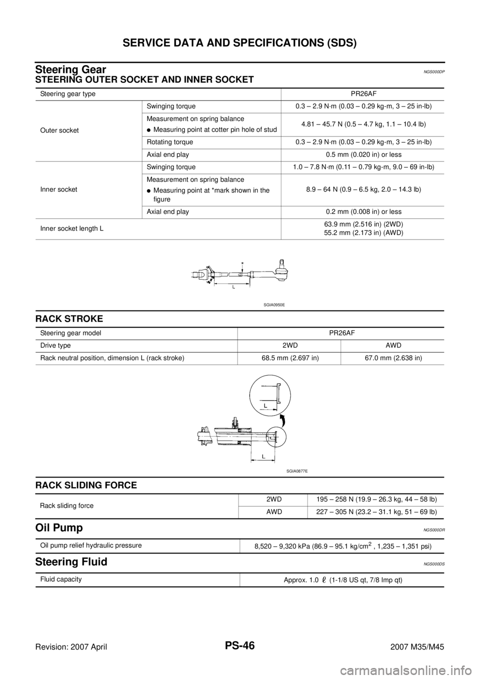
Steering gear typePR26AF
Outer socketSwinging torque 0.3 – 2.9 N·m (0.03 – 0.29 kg-m, 3 – 25 in-lb)
Measurement on spring balance
�Measuring point at cotter pin hole of stud4.81 – 45.7 N (0.5 – 4.7 kg, 1.1 – 10.4 lb)
Rotating torque 0.3 – 2.9 N·m (0.03 – 0.29 kg-m, 3 – 25 in-lb)
Axial end play 0.5 mm (0.020 in) or less
Inner socketSwinging torque 1.0 – 7.8 N·m (0.11 – 0.79 kg-m, 9.0 – 69 in-lb)
Measurement on spring balance
�Measuring point at *mark shown in the
figure8.9 – 64 N (0.9 – 6.5 kg, 2.0 – 14.3 lb)
Axial end play 0.2 mm (0.008 in) or less
Inner socket length L63.9 mm (2.516 in) (2WD)
55.2 mm (2.173 in) (AWD)
SGIA0950E
Steering gear modelPR26AF
Drive type 2WD AWD
Rack neutral position, dimension L (rack stroke) 68.5 mm (2.697 in) 67.0 mm (2.638 in)
SGIA0877E
Rack sliding force2WD 195 – 258 N (19.9 – 26.3 kg, 44 – 58 lb)
AWD 227 – 305 N (23.2 – 31.1 kg, 51 – 69 lb)
Oil pump relief hydraulic pressure
8,520 – 9,320 kPa (86.9 – 95.1 kg/cm2 , 1,235 – 1,351 psi)
Fluid capacity
Approx. 1.0 (1-1/8 US qt, 7/8 Imp qt)
Page 4073 of 4647
RFD-4
PREPARATION
Revision: 2007 April2007 M35/M45
KV38100800
(J-25604-01)
Attachment
a: 541 mm (21.30 in)
b: 200 mm (7.87 in)Fixing unit assembly
ST3127S000
(J-25765-A)
Preload gauge
1: GG91030000
(J-25765)
Torque wrench
2: HT62940000
(—)
Socket adapter (1/2″)
3: HT62900000
(—)
Socket adapter (3/8″)Measuring pinion bearing preload and total
preload
K V 1 0 1111 0 0
(J-37228)
Seal cutterRemoving rear cover
ST3306S001
(J-22888-D)
Differential side bearing puller set
1: ST33051001
(J-22888-20)
Puller
2: ST33061000
(J-8107-2)
Base
a: 28.5 mm (1.122 in) dia.
b: 38 mm (1.50 in) dia.Removing and installing side bearing inner
race
ST30031000
(J-22912-01)
ReplacerRemoving pinion rear bearing inner race
KV40105230
(—)
Drift
a: 92 mm (3.62 in) dia.
b: 86 mm (3.39 in) dia.
c: 45 mm (1.77 in) dia.Installing pinion rear bearing outer race Tool number
(Kent-Moore No.)
Tool nameDescription
SDIA0267E
NT124
S-NT046
NT072
ZZA0700D
PDIA0591E
Page 4091 of 4647

RFD-22
REAR FINAL DRIVE ASSEMBLY
Revision: 2007 April2007 M35/M45
Companion Flange Runout
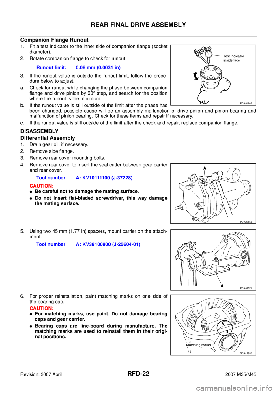
1. Fit a test indicator to the inner side of companion flange (socket
diameter).
2. Rotate companion flange to check for runout.
3. If the runout value is outside the runout limit, follow the proce-
dure below to adjust.
a. Check for runout while changing the phase between companion
flange and drive pinion by 90° step, and search for the position
where the runout is the minimum.
b. If the runout value is still outside of the limit after the phase has
been changed, possible cause will be an assembly malfunction of drive pinion and pinion bearing and
malfunction of pinion bearing. Check for these items and repair if necessary.
c. If the runout value is still outside of the limit after the check and repair, replace companion flange.
DISASSEMBLY
Differential Assembly
1. Drain gear oil, if necessary.
2. Remove side flange.
3. Remove rear cover mounting bolts.
4. Remove rear cover to insert the seal cutter between gear carrier
and rear cover.
CAUTION:
�Be careful not to damage the mating surface.
�Do not insert flat-bladed screwdriver, this way damage
the mating surface.
5. Using two 45 mm (1.77 in) spacers, mount carrier on the attach-
ment.
6. For proper reinstallation, paint matching marks on one side of
the bearing cap.
CAUTION:
�For matching marks, use paint. Do not damage bearing
caps and gear carrier.
�Bearing caps are line-board during manufacture. The
matching marks are used to reinstall them in their origi-
nal positions.Runout limit: 0.08 mm (0.0031 in)
PDIA0490E
Tool number A: KV10111100 (J-37228)
PDIA0756J
Tool number A: KV38100800 (J-25604-01)
PDIA0757J
SDIA1795E
Page 4110 of 4647
PREPARATION
RSU-3
C
D
F
G
H
I
J
K
L
MA
B
RSU
Revision: 2007 April2007 M35/M45
PREPARATIONPFP:00002
Special Service Tools [SST]NES000J3
The actual shapes of Kent-Moore tools may differ from those of special service tools illustrated here.
Commercial Service ToolsNES000J4
Tool number
(Kent-Moore No.)
Tool nameDescription
ST3127S000
(See J25742-1)
Preload Gauge
1. GG91030000
(J25765)
Torque wrench
2. HT62940000
(—)
Socket adapter
3. HT62900000
(—)
Socket adapterMeasuring rotating torque of ball joint
NT124
Tool nameDescription
Power tool
�Removing wheel nuts
�Removing brake caliper assembly
�Removing rear suspension component
parts
PBIC0190E
Page 4593 of 4647

WW-2Revision: 2007 April2007 M35/M45 CHECK VALVE INSPECTION ............................. 47
Inspection of Front Wiper and Washer Switch Circuit ... 47
Removal and Installation of Front Wiper and Washer
Switch ..................................................................... 47
REMOVAL ........................................................... 47
INSTALLATION .................................................... 47
Removal and Installation of Washer Tank .............. 48
REMOVAL ........................................................... 48
INSTALLATION .................................................... 48
Removal and Installation of Washer Pump ............. 49
REMOVAL ........................................................... 49
INSTALLATION .................................................... 49
CIGARETTE LIGHTER ............................................. 50
Wiring Diagram — CIGAR — ................................. 50
Removal and Installation ........................................ 51
REMOVAL ........................................................... 51
INSTALLATION .................................................... 51POWER SOCKET ..................................................... 52
Wiring Diagram — P/SCKT — ................................ 52
Removal and Installation of Center Console Box
Power Socket .......................................................... 53
REMOVAL ............................................................ 53
INSTALLATION .................................................... 53
Removal and Installation of Center Console Box
Rear Side Power Socket ......................................... 53
REMOVAL ............................................................ 53
INSTALLATION .................................................... 53
HORN ........................................................................ 54
Wiring Diagram — HORN — .................................. 54
Removal and Installation ......................................... 55
REMOVAL ............................................................ 55
INSTALLATION .................................................... 55
Page 4642 of 4647
CIGARETTE LIGHTER
WW-51
C
D
E
F
G
H
I
J
L
MA
B
WW
Revision: 2007 April2007 M35/M45
Removal and InstallationNKS003XA
REMOVAL
1. Remove A/T console finisher. Refer to IP-10, "INSTRUMENT PANEL ASSEMBLY" .
2. Remove screws (A) from reverse side cigarette lighter socket.
3. Pull out cigarette lighter (1).
4. Insert a small screwdriver or similar tool between the cigarette
lighter socket (2) and cigarette lighter ring (3). Pull out cigarette
lighter socket (2).
INSTALLATION
Note the following, and installation is the reverse order of removal.
CAUTION:
Align notches of cigarette lighter ring and cigarette lighter socket when installing.
SKIB4207E
SKIB4262E
Page 4643 of 4647
WW-52
POWER SOCKET
Revision: 2007 April2007 M35/M45
POWER SOCKETPFP:253A2
Wiring Diagram — P/SCKT —NKS003XB
TKWT3220E