Page 4000 of 4647

POWER STEERING GEAR AND LINKAGE
PS-19
C
D
E
F
H
I
J
K
L
MA
B
PS
Revision: 2007 April2007 M35/M45
POWER STEERING GEAR AND LINKAGEPFP:49001
Removal and InstallationNGS000DC
COMPONENTS
CAUTION:
Spiral cable may be cut if steering wheel turns while separating steering column assembly and steer-
ing gear assembly. Be sure to secure steering wheel using string to avoid turning.
REMOVAL
1. Set vehicle to the straight-ahead position.
2. Remove tires from vehicle with a power tool.
3. Remove undercover from vehicle with a power tool.
4. Remove lower side fixing bolt of lower joint.
5. Remove cotter pin (1), and then loosen the nut.
6. Remove steering outer socket (2) from steering knuckle (3) so
as not to damage ball joint boot (4) using the ball joint remover
(suitable tool).
CAUTION:
Temporarily tighten the nut to prevent damage to threads
and to prevent the ball joint remover from suddenly coming
off.
7. Remove high and low pressure piping of hydraulic piping, and
then drain power steering fluid. Refer to PS-39, "
HYDRAULIC
LINE" .
1. Cotter pin 2. Steering gear assembly 3. Steering gear assembly
(AWD models)
Refer to GI-11, "
Components" , for the symbols in the figure.
SGIA1387E
SGIA0844E
SGIA1183E
Page 4002 of 4647

POWER STEERING GEAR AND LINKAGE
PS-21
C
D
E
F
H
I
J
K
L
MA
B
PS
Revision: 2007 April2007 M35/M45
Disassembly and AssemblyNGS000DD
COMPONENTS
CAUTION:
�Disassemble and assemble steering gear assembly by securing the mounting area in a vise using
copper plates.
�Clean steering gear assembly with kerosene before disassembling. Be careful to avoid splashing
or applying any kerosene over connector of discharge port or return port.
1. Outer socket 2. Boot clamp 3. Boot
4. Inner socket 5. Boot clamp (stainless wire) 6. End cover assembly
7. Rack oil seal 8. Rack Teflon ring 9. O-ring
10. Rack assembly 11. Gear housing assembly 12. Cylinder tubes
13. O-ring 14. Gear-sub assembly 15. power steering solenoid valve
16. Rear cover cap
Refer to GI-11, "
Components" , and the followings for the symbols in the figure.
: Apply power steering fluid.
: A p p l y G e n u i n e L i q u i d G a s k e t , T h r e e B o n d 1111 B o r e q u i v a l e n t .
: Apply multi-purpose grease.
SGIA1388E
Page 4012 of 4647
POWER STEERING OIL PUMP
PS-31
C
D
E
F
H
I
J
K
L
MA
B
PS
Revision: 2007 April2007 M35/M45
Disassembly and Assembly (Models with VK45DE)NGS000DG
COMPONENTS
INSPECTION BEFORE DISASSEMBLY
Disassemble oil pump only when the following malfunctions occur.
�If oil leakage is found on oil pump.
�Oil pump pulley is damaged or deformed.
�Performance of oil pump is low.
1. Pulley 2. Snap ring 3. Drive shaft
4. Joint 5. O-ring 6. Connector bolt
7. Flow control valve 8. Spring 9. Oil seal
10. Suction pipe 11. O-ring 12. Body assembly
13. O-ring 14. Side plate 15. Vane
16. Rotor 17. Cam ring 18. Cartridge
19. Dowel pin 20. Gasket 21. Rear cover
22. Copper washer
Refer to GI-11, "
Components" , and the followings for the symbols in the figure.
: Apply power steering fluid.
: Apply multi-purpose grease.
SGIA1187E
Page 4016 of 4647
POWER STEERING OIL PUMP
PS-35
C
D
E
F
H
I
J
K
L
MA
B
PS
Revision: 2007 April2007 M35/M45
Disassembly and Assembly (Models with VQ35DE)NGS000DH
COMPONENTS
INSPECTION BEFORE DISASSEMBLY
Disassemble oil pump only when the following malfunctions occur.
�If oil leakage is found on oil pump.
�Oil pump pulley is damaged or deformed.
�Performance of oil pump is low.
1. Pulley 2. Oil seal 3. Bracket
4. Body assembly 5. Suction pipe 6. O-ring
7. Flow control valve B assembly 8. Flow control valve spring 9. Flow control valve A
10. Dowel pin 11. Front side plate 12. Vane
13. Rotor 14. Rotor snap ring 15. Cam ring
16. Rear side plate 17. O-ring 18. Teflon ring
19. O-ring 20. Rear cover 21. Cartridge
Refer to GI-11, "
Components" , and the followings for the symbols in the figure.
: Apply power steering fluid.
: Apply multi-purpose grease.
SGIA1188E
Page 4021 of 4647
PS-40
HYDRAULIC LINE
Revision: 2007 April2007 M35/M45
10. Eye-bolt 11. Copper washer 12. Eye-joint (assembled to high-pres-
sure side hose)
13. Pressure sensor 14. Oil pump bracket
Refer to GI-11, "
Components" , and the followings for the symbols in the figure.
: Apply power steering fluid.
Page 4023 of 4647
PS-42
HYDRAULIC LINE
Revision: 2007 April2007 M35/M45
Refer to GI-11, "Components" , and the followings for the symbols in the figure.
: Apply power steering fluid.
Page 4025 of 4647
PS-44
HYDRAULIC LINE
Revision: 2007 April2007 M35/M45
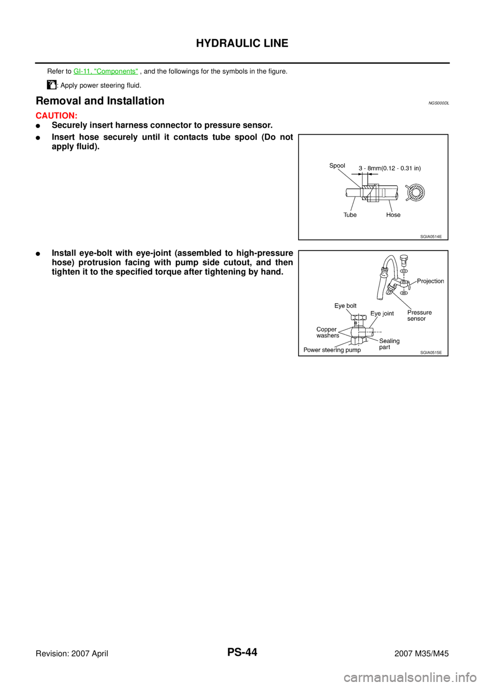
Removal and InstallationNGS000DL
CAUTION:
�Securely insert harness connector to pressure sensor.
�Insert hose securely until it contacts tube spool (Do not
apply fluid).
�Install eye-bolt with eye-joint (assembled to high-pressure
hose) protrusion facing with pump side cutout, and then
tighten it to the specified torque after tightening by hand.
Refer to GI-11, "Components" , and the followings for the symbols in the figure.
: Apply power steering fluid.
SGIA0514E
SGIA0515E
Page 4032 of 4647
 of each component")
WHEEL HUB
RAX-5
C
E
F
G
H
I
J
K
L
MA
B
RAX
Revision: 2007 April2007 M35/M45
WHEEL HUBPFP:43202
On-Vehicle Inspection NDS000FQ
Make sure the mounting conditions (looseness, back lash) of each component and component conditions
(wear, damage) are normal.
WHEEL BEARING INSPECTION
�Move wheel hub and bearing assembly in the axial direction by hand. Make sure there is no looseness of
wheel bearing.
�Rotate wheel hub, and make sure that is no unusual noise or other irregular conditions. If there is any of
irregular conditions, replace wheel hub and bearing assembly.
Removal and InstallationNDS000FR
COMPONENT
REMOVAL
Wheel Hub and Bearing Assembly
1. Remove tires from vehicle with a power tool.
2. Remove rear brake caliper with a power tool. Hang it in a place where it will not interfere with work. Refer
to BR-30, "
Removal and Installation of Brake Caliper Assembly" .
CAUTION:
Do not depress brake pedal while brake caliper is removed.
3. Put matching mark on disc rotor and the wheel hub and bearing
assembly then removing disc rotor.
4. Remove cotter pin, then loosen hub lock nut with a power tool.Axial end play : 0.05 mm (0.002 in) or less
1. Axle housing 2. Ball seat 3. Bushing
4. Back plate 5. Anchor block 6. Wheel hub and bearing assembly
7. Cotter pin
Refer to GI-11, "
Components" , for the symbols in the figure.
SDIA3251E
SDIA2638E
NGS000DG
COMPONENTS
INSPECTION BEFORE DISASSEMBLY
Disassemble oil")
NGS000DH
COMPONENTS
INSPECTION BEFORE DISASSEMBLY
Disassemble oil")

13. Pressure sensor 14. Oil pump bracket
Refer to GI-11, \"")