Page 3778 of 4647
![INFINITI M35 2007 Factory Service Manual OIL FILTER BRACKET (AWD)
LU-13
[VQ35DE]
C
D
E
F
G
H
I
J
K
L
MA
LU
Revision: 2007 April2007 M35/M45
OIL FILTER BRACKET (AWD)PFP:15238
ComponentsNBS004PZ
�Refer to GI-11, "Components" for symbols in th](/manual-img/42/57024/w960_57024-3777.png "INFINITI M35 2007 Factory Service Manual OIL FILTER BRACKET (AWD)
LU-13
[VQ35DE]
C
D
E
F
G
H
I
J
K
L
MA
LU
Revision: 2007 April2007 M35/M45
OIL FILTER BRACKET (AWD)PFP:15238
ComponentsNBS004PZ
�Refer to GI-11, \"Components\" for symbols in th")
OIL FILTER BRACKET (AWD)
LU-13
[VQ35DE]
C
D
E
F
G
H
I
J
K
L
MA
LU
Revision: 2007 April2007 M35/M45
OIL FILTER BRACKET (AWD)PFP:15238
ComponentsNBS004PZ
�Refer to GI-11, "Components" for symbols in the figure.
Removal and InstallationNBS004Q0
REMOVAL
WARNING:
Be careful not to get burn yourself, as engine oil may be hot.
1. Remove front engine undercover with power tool.
2. Using the oil filter wrench [SST: KV10115801 (J38956)], remove oil filter. Refer to LU-11, "
OIL FILTER" .
CAUTION:
Do not spill engine oil on drive belt.
3. Remove connector bolt, and then oil cooler with water hoses connected.
4. Disconnect oil pressure switch harness connectors.
5. Remove oil filter bracket from oil pan (upper).
6. Remove oil pressure switch from oil filter bracket.
INSTALLATION
Note the following, and install in the reverse order of removal.
�Install oil pressure switch as follows:
–Remove old liquid gasket adhering to oil filter bracket.
–Apply liquid gasket and install oil pressure switch.
1. Oil filter 2. Connector bolt 3. Oil cooler
4. O-ring 5. Relief valve 6. Oil filter bracket
7. Gasket 8. Oil pressure switch
A. Refer to LU-11
: Engine front
PBIC3393E
Page 3845 of 4647
PB-4
PARKING BRAKE CONTROL
Revision: 2007 April2007 M35/M45
PARKING BRAKE CONTROLPFP:36010
ComponentsNFS000ST
1. Device assembly 2. Parking brake switch 3. Pedal pad
4. Adjusting nut 5. Stopper rubber 6. Return spring
7. Spring insulator 8. Front cable 9. Equalizer
10. Spring 11. Rear cable (LH) 12. Pin
13. Rear cable (RH) 14. Lock plate
Refer to GI-11, "
Components" and the followings for the symbols in the figure.
: Apply Multi-purpose grease.
SFIA2962E
Page 3913 of 4647
PG-62
HARNESS
Revision: 2007 April2007 M35/M45
HARNESS PFP:00011
Harness Layout NKS004ES
HOW TO READ HARNESS LAYOUT
The following Harness Layouts use a map style grid to help locate
connectors on the figures:
�Main Harness (Instrument Panel)
�Engine Room Harness (Engine Compartment)
�Engine Control Harness (Engine Compartment)
�Body Harness
�Body No. 2 Harness
To Use the Grid Reference
1. Find the desired connector number on the connector list.
2. Find the grid reference.
3. On the figure, find the crossing of the grid reference letter column and number row.
4. Find the connector number in the crossing zone.
5. Follow the line (if used) to the connector.
CONNECTOR SYMBOL
Main symbols of connector (in Harness Layout) are indicated in the below.
SEL252V
CKIT0108E
Page 3971 of 4647

PR-4
FRONT PROPELLER SHAFT
Revision: 2007 April2007 M35/M45
FRONT PROPELLER SHAFTPFP:37200
On-Vehicle InspectionNDS000EA
APPEARANCE AND NOISE INSPECTION
�Check the propeller shaft tube surface for dents or cracks. If damaged, replace propeller shaft assembly.
PROPELLER SHAFT VIBRATION
If vibration is present at high speed, inspect propeller shaft runout first.
1. Measure propeller shaft runout at runout measuring point by
rotating final drive companion flange with hands. For measuring
point, refer to PR-4, "
Propeller Shaft Runout Measuring Point" .
2. If runout still exceeds specifications, separate propeller shaft at
final drive companion flange; then rotate companion flange 90,
180, 270 degrees and install propeller shaft.
3. Check runout again. If runout still exceeds specifications,
replace propeller shaft assembly.
4. Check the vibration by driving vehicle.
Propeller Shaft Runout Measuring Point
�Propeller shaft runout measuring point (Point “ ”)
ComponentsNDS000EB
Propeller shaft runout limit : 0.8 mm (0.031 in)
PDIA0767J
Dimension A: 381.5 mm (15.01 in)
PDIA0768J
1. Propeller shaft assembly 2. Heat bracket (A) 3. Heat bracket (B)
4. O-ring
Refer to GI-11, "
Components" , for the symbols in the figure.
PDIA0769J
Page 3974 of 4647
REAR PROPELLER SHAFT
PR-7
C
E
F
G
H
I
J
K
L
MA
B
PR
Revision: 2007 April2007 M35/M45
ComponentsNDS000EE
VQ35DE 2WD MODELS (3S80A-1VL107 TYPE)
VK45DE 2WD MODELS (3F-R-2VL107 TYPE)
PDIA0964E
1. Propeller shaft (1st shaft) 2. Center flange 3. Center bearing mounting bracket
(Lower)
4. Floor reinforcement 5. Center bearing assembly 6. Propeller shaft (2nd shaft)
7. Clip 8. Center bearing mounting bracket
(Upper)9. Washer
10. Lock nut
A: Both side
B: For the tightening torque, refer to PR-12, "
ASSEMBLY" .
Refer to GI-11, "
Components" , for the symbols in the figure.
PDIA0965E
1. Propeller shaft (1st shaft) 2. Center bearing mounting bracket
(Lower)3. Floor reinforcement
4. Propeller shaft (2nd shaft) 5. Clip 6. Center bearing mounting bracket
(Upper)
Refer to GI-11, "
Components" , for the symbols in the figure.
Page 3975 of 4647

Removal and InstallationNDS000EF
REMOVAL
1. Move the A/T select lever to N position and release the par")
PR-8
REAR PROPELLER SHAFT
Revision: 2007 April2007 M35/M45
VQ35DE AWD MODELS (3F80A-1VL107 TYPE)
Removal and InstallationNDS000EF
REMOVAL
1. Move the A/T select lever to N position and release the parking brake.
2. Remove the floor reinforcement.
3. Remove the center muffler with power tool. Refer to EX-3, "
EXHAUST SYSTEM" .
4.For VQ35DE 2WD models
�Put matching marks on propeller shaft rebro joint with final
drive companion flange.
CAUTION:
For matching marks, use paint. Do not damage propeller
shaft rebro joint and companion flange.
For VK45DE 2WD models
�Put matching marks on propeller shaft rubber coupling with
transmission companion flange and on rebro joint with final
drive companion flange.
CAUTION:
For matching marks, use paint. Do not damage rubber coupling, rebro joint and companion
flanges.
For VQ35DE AWD models
�Put matching marks on propeller shaft flange yoke with transfer companion flange and on rebro joint
with final drive companion flange.
CAUTION:
For matching marks, use paint. Do not damage propeller shaft flange yoke, rebro joint and com-
panion flanges.
PDIA0966E
1. Propeller shaft (1st shaft) 2. Center flange 3. Center bearing mounting bracket
(Lower)
4. Floor reinforcement 5. Center bearing assembly 6. Propeller shaft (2nd shaft)
7. Clip 8. Center bearing mounting bracket
(Upper)9. Washer
10. Lock nut
A: Both side
B: For the tightening torque, refer to PR-12, "
ASSEMBLY" .
Refer to GI-11, "
Components" , for the symbols in the figure.
PDIA0470E
Page 3994 of 4647
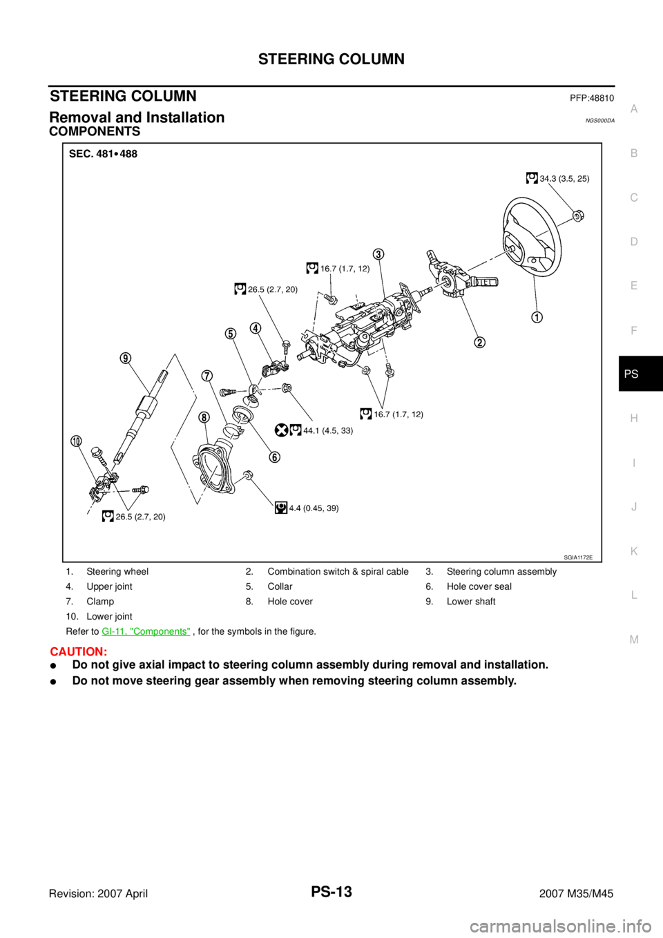
STEERING COLUMN
PS-13
C
D
E
F
H
I
J
K
L
MA
B
PS
Revision: 2007 April2007 M35/M45
STEERING COLUMNPFP:48810
Removal and InstallationNGS000DA
COMPONENTS
CAUTION:
�Do not give axial impact to steering column assembly during removal and installation.
�Do not move steering gear assembly when removing steering column assembly.
1. Steering wheel 2. Combination switch & spiral cable 3. Steering column assembly
4. Upper joint 5. Collar 6. Hole cover seal
7. Clamp 8. Hole cover 9. Lower shaft
10. Lower joint
Refer to GI-11, "
Components" , for the symbols in the figure.
SGIA1172E
Page 3998 of 4647

STEERING COLUMN
PS-17
C
D
E
F
H
I
J
K
L
MA
B
PS
Revision: 2007 April2007 M35/M45
Disassembly and AssemblyNGS000DB
COMPONENTS
DISASSEMBLY
1. Remove fixing screws of telescopic sensor, and then remove telescopic sensor from steering column.
2. Remove fixing screw of bracket, and then remove bracket from telescopic motor.
3. Remove fixing bolt of telescopic motor, and then remove telescopic motor from steering column.
4. Remove fixing screws of tilt sensor, and then remove tilt sensor from steering column.
5. Remove fixing bolt of tilt motor, and then remove tilt motor from steering column.
6. Remove fixing screws of brackets, and then remove brackets from steering column.
INSPECTION AFTER DISASSEMBLY
Check component parts for damage or other malfunctions. Replace if there are.
ASSEMBLY
Assembly is the reverse order of disassembly. For tightening torque, refer to PS-17, "COMPONENTS" .
1. Bracket 2. Bracket 3. Steering column
4. Telescopic motor 5. Bracket 6. Telescopic sensor
7. Tilt sensor 8. Tilt motor 9. Bracket
10. Bracket
Refer to GI-11, "
Components" , for the symbols in the figure.
SGIA1634E


VK45DE 2WD MODELS (3F-R-2VL107 TYPE)
PDIA0964E
1. Propelle")