Page 363 of 4647
AT-284
OVERHAUL
Revision: 2007 April2007 M35/M45
7. Converter housing 8. Oil pump housing oil seal 9. Bearing race
10. Needle bearing 11. O-ring 12. Front carrier assembly
13. Needle bearing 14. Snap ring 15. Front sun gear
16. 3rd one-way clutch 17. Snap ring 18. Bearing race
19. Needle bearing 20. Seal ring 21. Input clutch assembly
22. Needle bearing 23. Rear internal gear 24. Brake band
25. Mid carrier assembly 26. Needle bearing 27. Bearing race
28. Rear carrier assembly 29. Needle bearing 30. Mid sun gear
31. Seal ring 32. Rear sun gear 33. 1st one-way clutch
34. Snap ring 35. Needle bearing 36. High and low reverse clutch hub
37. Snap ring 38. Bearing race 39. Needle bearing
Refer to GI section to make sure icons (symbol marks) in the figure. Refer to GI-11, "
Components" .
However, refer to the following symbols for others.
:Apply Genuine RTV silicone sealant or equivalent. Refer to GI-47, "
Recommended Chemical Products and Sealants" .
Page 369 of 4647
AT-290
OVERHAUL
Revision: 2007 April2007 M35/M45
7. Pawl shaft 8. Seal ring 9. Needle bearing
10. Revolution sensor 11. Parking gear 12. Output shaft
13. Bearing race 14. Needle bearing 15. Manual plate
16. Parking rod 17. Manual shaft oil seal 18. Manual shaft
19. O-ring 20. Band servo anchor end pin 21. Detent spring
22. Spacer 23. Seal ring 24. Snap ring
25. Return spring 26. O-ring 27. Servo assembly
28. Snap ring 29. Sub-harness 30. Control valve with TCM
31. Bracket 32. A/T fluid temperature sensor 2 33. Clip
34. Oil pan mounting bolt 35. Oil pan 36. Magnet
37. Drain plug 38. Drain plug gasket 39. Oil pan gasket
40. Terminal cord assembly 41. O-ring 42. Retaining pin
43. Transmission case
Refer to GI section to make sure icons (symbol marks) in the figure. Refer to GI-11, "
Components" .
However, refer to the following symbols for others.
*:Apply Genuine Anaerobic Liquid Gasket or equivalent. Refer to GI-47, "Recommended Chemical Products and Sealants"
.
Page 371 of 4647

AT-292
OVERHAUL
Revision: 2007 April2007 M35/M45
1. Output shaft & companion flange
complement2. Parking actuator support 3. Parking pawl
4. Return spring 5. Pawl shaft 6. Self-sealing bolt
7. Seal ring 8. Needle bearing 9. Revolution sensor
10. Intermediate shaft 11. Manual plate 12. Parking rod
13. Manual shaft oil seal 14. Manual shaft 15. Retaining pin
16. O-ring 17. Band servo anchor end pin 18. Detent spring
19. Spacer 20. Return spring 21. Seal ring
22. O-ring 23. Servo assembly 24. Snap ring
25. Snap ring 26. Sub-harness 27. Control valve with TCM
28. Bracket 29. A/T fluid temperature sensor 2 30. Terminal cord assembly
31. O-ring 32. Clip 33. Bracket
34. Bracket 35. Oil pan mounting bolt 36. Oil pan
37. Magnet 38. Drain plug 39. Drain plug gasket
40. Oil pan gasket 41. Transmission case
Refer to GI section to make sure icons (symbol marks) in the figure. Refer to GI-11, "
Components" .
However, refer to the following symbols for others.
*:Apply Genuine Anaerobic Liquid Gasket or equivalent. Refer to GI-47, "Recommended Chemical Products and Sealants" .
Page 1245 of 4647
BL-312
BODY REPAIR
Revision: 2007 April2007 M35/M45
The symbols used in this section for cutting and welding / brazing operations are shown below.
PIIA0149E
Page 1274 of 4647
BRAKE PEDAL
BR-7
C
D
E
G
H
I
J
K
L
MA
B
BR
Revision: 2007 April2007 M35/M45
Removal and InstallationNFS000RU
COMPONENTS
WITHOUT PRE-CRASH SEAT BELT
WITH PRE-CRASH SEAT BELT
NOTE:
Clevis pin can be installed from both left and right.
PFIA0838E
1. Clevis pin 2. Snap pin 3. Stop lamp switch
4. Brake switch 5. Clip 6. Brake pedal assembly
7. Brake pedal pad
Refer to GI-11, "
Components" and the followings for the symbols in the figure.
: Apply Multi-purpose grease.
PFIA0839E
1. Clevis pin 2. Brake pedal stroke sensor 3. Snap pin
4. Stop lamp switch 5. Brake switch 6. Clip
7. Brake pedal assembly 8. Brake pedal pad
Refer to GI-11, "
Components" and the followings for the symbols in the figure.
: Apply Multi-purpose grease.
Page 1279 of 4647

BR-12
BRAKE TUBE AND HOSE
Revision: 2007 April2007 M35/M45
CAUTION:
�All brake hoses and tubes must be free from excessive bending, twisting and pulling.
�Make sure that there is no interference with other parts when turning steering both clockwise and
counterclockwise.
�Brake tubes and hoses are an important safety part. Always disassemble the parts and retighten
their fittings, if a brake fluid leak is detected. Replace applicable part with a new one, if damaged
part is detected.
�Be careful not to splash brake fluid on painted areas; it may cause paint damage. If brake fluid is
splashed on painted areas, wash it away with water immediately.
�Cover the open end of brake tubes and hoses when disconnecting to prevent entrance of dirt.
�Refill with new brake fluid “DOT 3”.
�Never reuse drained brake fluid.
Removal and Installation of Front Brake Tube and Brake Hose NFS000S0
REMOVAL
1. Drain brake fluid. Refer to BR-9, "Drain and Refill" .
2. Disconnect brake hose from brake tube, using a flare nut wrench.
3. Remove union bolt and remove brake hose from caliper assem-
bly.
4. Remove lock plate and remove brake hose from vehicle.
INSTALLATION
1. Assemble the union bolt and copper washer to the brake hose.
CAUTION:
Do not reuse copper washer.
2. Install brake hose by aligning with the protrusion on brake caliper assembly, and tighten union bolt to the
specified torque. Refer to BR-11, "
Hydraulic Circuit" .
3. Connect brake hose to brake tube, partially tighten flare nut by hand as much as possible, then secure it
to the bracket with lock plate.
4. Using a flare nut torque wrench, tighten flare nut to the specified torque. Refer to BR-11, "
Hydraulic Cir-
cuit" .
5. Refill brake fluid and bleed air. Refer to BR-10, "
Bleeding Brake System" .
Removal and Installation of Rear Brake Tube and Brake Hose NFS000S1
REMOVAL
1. Drain brake fluid. Refer to BR-9, "Drain and Refill" .
A. With out ICC B. With ICC 1. Front disc brake
2. Master cylinder 3. Brake booster 4. Rear disc brake
5. ABS actuator and electric unit (con-
trol unit)6. Connector 7. Brake hose
8. Brake tube
: Flare nut : 18.2 N·m (1.9 kg-m, 13 ft-lb)
: Flare nut : 16.2 N·m (1.7 kg-m, 12 ft-lb)
: Union bolt :18.2 N·m (1.9 kg-m, 13 ft-lb)
: Connector mounting bolt : 7.0 N·m (0.7 kg-m, 62 in-lb)
Refer to GI-11, "
Components" , for the symbols in the figure.
SFIA2964E
Page 1282 of 4647
BRAKE MASTER CYLINDER
BR-15
C
D
E
G
H
I
J
K
L
MA
B
BR
Revision: 2007 April2007 M35/M45
Disassembly and AssemblyNFS000S5
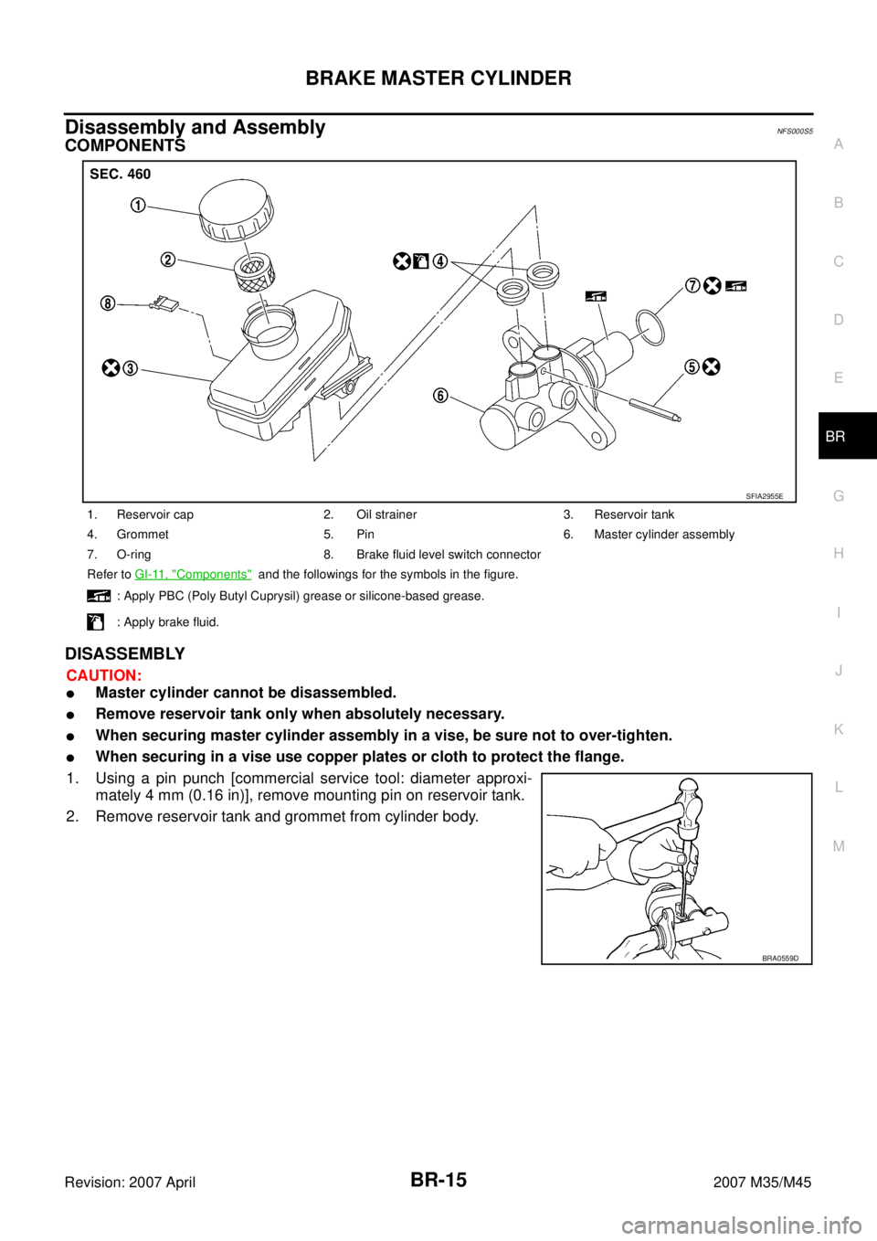
COMPONENTS
DISASSEMBLY
CAUTION:
�Master cylinder cannot be disassembled.
�Remove reservoir tank only when absolutely necessary.
�When securing master cylinder assembly in a vise, be sure not to over-tighten.
�When securing in a vise use copper plates or cloth to protect the flange.
1. Using a pin punch [commercial service tool: diameter approxi-
mately 4 mm (0.16 in)], remove mounting pin on reservoir tank.
2. Remove reservoir tank and grommet from cylinder body.
1. Reservoir cap 2. Oil strainer 3. Reservoir tank
4. Grommet 5. Pin 6. Master cylinder assembly
7. O-ring 8. Brake fluid level switch connector
Refer to GI-11, "
Components" and the followings for the symbols in the figure.
: Apply PBC (Poly Butyl Cuprysil) grease or silicone-based grease.
: Apply brake fluid.
SFIA2955E
BRA0559D
Page 1285 of 4647

BR-18
BRAKE BOOSTER
Revision: 2007 April2007 M35/M45
Removal and InstallationNFS000S8
COMPONENTS
CAUTION:
�Be careful not to deform or bend brake tube while removing and installing brake booster.
�Replace clevis pin if it is damaged.
�Be careful not to damage brake booster stud bolt threads. If brake booster is tilted during installa-
tion, the dash panel may damage the threads.
REMOVAL
1. Remove cowl top. Refer to EI-18, "Removal and Installation" .
2. Remove brake master cylinder. Refer to BR-14, "
Removal and
Installation" .
3. Disconnect front left brake tube from ABS actuator and electric
unit (control unit). Refer to BR-11, "
Hydraulic Circuit" .
4. Remove vacuum hose from brake booster. Refer to BR-20,
"Components" .
5. Remove snap pin and clevis pin from inside vehicle.
6. Remove nuts on brake booster and brake pedal assembly.
7. Remove brake booster from dash panel in engine room side.
INSTALLATION
1. Loosen lock nut to adjust input rod length so that length “B” (in
the figure) satisfies the specified value.
2. After adjusting “B”, temporarily tighten lock nut to install booster
assembly to vehicle. At this time, make sure that a gasket
between booster assembly and dash panel is installed.
CAUTION:
Always install gasket between brake booster and dash
panel.
3. Connect brake pedal with clevis of input rod.
1. Master cylinder assembly 2. Brake booster 3. Lock nut
4. Brake pedal 5. Gasket
Refer to GI-11, "
Components" , for the symbols in the figure.
SFIA2956E
SFIA2044E
Length “B” : 125 mm (4.92 in)
SGIA0060E