Page 1289 of 4647

BR-22
FRONT DISC BRAKE
Revision: 2007 April2007 M35/M45
FRONT DISC BRAKEPFP:41000
On-Board InspectionNFS000SC
PAD WEAR INSPECTION
�Check pad thickness from an inspection hole on cylinder body.
Check using a scale if necessary.
ComponentsNFS000SD
WARNING:
Clean dust on caliper and brake pad with a vacuum dust collector to minimize the hazard of air borne
particles or other materials.
CAUTION:
�While removing cylinder body, do not depress brake pedal because piston will pop out. Standard thickness : 11.0 mm (0.433 in)
Repair limit thickness : 2.0 mm (0.079 in)
MAA0439D
1. Union bolt 2. Copper washer 3. Brake hose
4. Cap 5. Bleed valve 6. Sliding pin bolt
7. Piston seal 8. Piston 9. Piston boot
10. Cylinder body 11. Sliding pin 12. Torque member mounting bolt
13. Washer 14. Sliding pin boot 15. Bushing
16. Torque member 17. Inner shim cover 18. Inner shim
19. Inner pad 20. Pad retainer 21. Pad wear sensor
22. Outer pad 23. Outer shim 24. Outer shim cover
Refer to GI-11, "
Components" and the followings for the symbols in the figure.
1: Apply rubber grease.
2: Apply PBC (Poly Butyl Cuprysil) grease or silicone-based grease.
3: Apply polyglycol ether based lubricant.
: Apply brake fluid.
PFIA0820E
Page 1295 of 4647
BR-28
REAR DISC BRAKE
Revision: 2007 April2007 M35/M45
REAR DISC BRAKEPFP:44000
On-Board InspectionNFS000SH
PAD WEAR INSPECTION
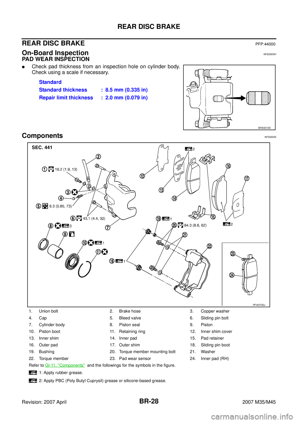
�Check pad thickness from an inspection hole on cylinder body.
Check using a scale if necessary.
ComponentsNFS000SI
Standard
Standard thickness : 8.5 mm (0.335 in)
Repair limit thickness : 2.0 mm (0.079 in)
BRA0010D
1. Union bolt 2. Brake hose 3. Copper washer
4. Cap 5. Bleed valve 6. Sliding pin bolt
7. Cylinder body 8. Piston seal 9. Piston
10. Piston boot 11. Retaining ring 12. Inner shim cover
13. Inner shim 14. Inner pad 15. Pad retainer
16. Outer pad 17. Outer shim 18. Sliding pin boot
19. Bushing 20. Torque member mounting bolt 21. Washer
22. Torque member 23. Pad wear sensor 24. Inner pad (RH)
Refer to GI-11, "
Components" and the followings for the symbols in the figure.
1: Apply rubber grease.
2: Apply PBC (Poly Butyl Cuprysil) grease or silicone-based grease.
PFIA0705J
Page 1375 of 4647
![INFINITI M35 2007 Factory Service Manual CO-14
[VQ35DE]
RADIATOR
Revision: 2007 April2007 M35/M45
RADIATORPFP:21400
ComponentsNBS004QS
�Refer to GI-11, "Components" for symbols in the figure.
Removal and InstallationNBS004QT
WARNING:
Do not](/manual-img/42/57024/w960_57024-1374.png "INFINITI M35 2007 Factory Service Manual CO-14
[VQ35DE]
RADIATOR
Revision: 2007 April2007 M35/M45
RADIATORPFP:21400
ComponentsNBS004QS
�Refer to GI-11, \"Components\" for symbols in the figure.
Removal and InstallationNBS004QT
WARNING:
Do not")
CO-14
[VQ35DE]
RADIATOR
Revision: 2007 April2007 M35/M45
RADIATORPFP:21400
ComponentsNBS004QS
�Refer to GI-11, "Components" for symbols in the figure.
Removal and InstallationNBS004QT
WARNING:
Do not remove radiator cap when engine is hot. Serious burns could occur from high-pressure engine
coolant escaping from radiator. Wrap a thick cloth around the cap. Slowly turn it a quarter of a turn to
release built-up pressure. Carefully remove radiator cap by turning it all the way.
REMOVAL
1. Remove the following parts:
�Front engine undercover (power tool).
�Engine room cover (RH and LH). Refer to EM-15, "ENGINE ROOM COVER" .
�Air duct (inlet) and air cleaner case assembly. Refer to EM-19, "AIR CLEANER AND AIR DUCT" .
1. Reservoir tank cap 2. Reservoir tank 3. Reservoir tank bracket
4. Reservoir tank hose 5. Radiator hose (upper) 6. Air guide
7. Mount bracket (RH) 8. Mounting rubber (upper) 9. A/C condenser
10. Radiator cap 11. Mount bracket (LH) 12. Radiator
13. Mounting rubber (lower) 14. A/T fluid cooler hose 15. A/T fluid cooler hose
16. O-ring 17. Drain plug 18. Radiator hose (lower)
19. Cooling fan assembly
A. To water outlet B. To water inlet C. To transmission
D. To transmission
PBIC4717E
Page 1390 of 4647
![INFINITI M35 2007 Factory Service Manual WATER INLET AND THERMOSTAT ASSEMBLY
CO-29
[VQ35DE]
C
D
E
F
G
H
I
J
K
L
MA
CO
Revision: 2007 April2007 M35/M45
WATER INLET AND THERMOSTAT ASSEMBLYPFP:21200
ComponentsNBS004R3
�Refer to GI-11, "Componen](/manual-img/42/57024/w960_57024-1389.png "INFINITI M35 2007 Factory Service Manual WATER INLET AND THERMOSTAT ASSEMBLY
CO-29
[VQ35DE]
C
D
E
F
G
H
I
J
K
L
MA
CO
Revision: 2007 April2007 M35/M45
WATER INLET AND THERMOSTAT ASSEMBLYPFP:21200
ComponentsNBS004R3
�Refer to GI-11, \"Componen")
WATER INLET AND THERMOSTAT ASSEMBLY
CO-29
[VQ35DE]
C
D
E
F
G
H
I
J
K
L
MA
CO
Revision: 2007 April2007 M35/M45
WATER INLET AND THERMOSTAT ASSEMBLYPFP:21200
ComponentsNBS004R3
�Refer to GI-11, "Components" for symbols in the figure.
Removal and InstallationNBS004R4
REMOVAL
1. Remove engine room cover (RH and LH). Refer to EM-15, "ENGINE ROOM COVER" .
2. Remove air duct (inlet). Refer to EM-19, "
AIR CLEANER AND AIR DUCT" .
3. Remove front engine undercover using power tool.
4. Drain engine coolant from radiator drain plug at the bottom of radiator, and from water drain plug at the
front of cylinder block. Refer to CO-11, "
Changing Engine Coolant" and CO-24, "WATER PUMP" .
CAUTION:
�Perform this step when the engine is cold.
�Do not spill engine coolant on drive belts.
5. Disconnect radiator hose (lower) and oil cooler water hose from water inlet and thermostat assembly.
6. Remove water inlet and thermostat assembly.
CAUTION:
Do not disassemble water inlet and thermostat assembly.
Replace them as a unit, if necessary.
1. Water inlet and thermostat assembly 2. Gasket
A. To oil cooler
PBIC5002E
SLC962AB
Page 1404 of 4647
![INFINITI M35 2007 Factory Service Manual RADIATOR
CO-43
[VK45DE]
C
D
E
F
G
H
I
J
K
L
MA
CO
Revision: 2007 April2007 M35/M45
RADIATORPFP:21400
ComponentsNBS004RG
�Refer to GI-11, "Components" for symbols in the figure.
Removal and Installati](/manual-img/42/57024/w960_57024-1403.png "INFINITI M35 2007 Factory Service Manual RADIATOR
CO-43
[VK45DE]
C
D
E
F
G
H
I
J
K
L
MA
CO
Revision: 2007 April2007 M35/M45
RADIATORPFP:21400
ComponentsNBS004RG
�Refer to GI-11, \"Components\" for symbols in the figure.
Removal and Installati")
RADIATOR
CO-43
[VK45DE]
C
D
E
F
G
H
I
J
K
L
MA
CO
Revision: 2007 April2007 M35/M45
RADIATORPFP:21400
ComponentsNBS004RG
�Refer to GI-11, "Components" for symbols in the figure.
Removal and InstallationNBS004RH
WARNING:
Do not remove radiator cap when engine is hot. Serious burns could occur from high-pressure engine
coolant escaping from thermostat housing. Wrap a thick cloth around radiator cap. Slowly turn it a
quarter of a turn to release built-up pressure. Carefully remove radiator cap by turning it all the way.
REMOVAL
1. Remove the following parts:
�Front engine undercover (power tool).
�Engine room cover (RH and LH). Refer to EM-173, "ENGINE ROOM COVER" .
�Air duct (inlet) and air cleaner case assembly. Refer to EM-177, "AIR CLEANER AND AIR DUCT" .
2. Remove front grille and front grille support. Refer to EI-16, "
FRONT GRILLE" .
3. Drain engine coolant from radiator. Refer to CO-40, "
ENGINE COOLANT" .
1. Reservoir tank cap 2. Reservoir tank 3. Reservoir tank bracket
4. Reservoir tank hose 5. Radiator hose (upper) 6. Air guide
7. Mount bracket (RH) 8. Mounting rubber (upper) 9. A/C condenser
10. Mount bracket (LH) 11. Radiator 12. Mounting rubber (lower)
13. A/T fluid cooler hose 14. A/T fluid cooler hose 15. O-ring
16. Drain plug 17. Radiator hose (lower) 18. Cooling fan assembly
A. To thermostat housing B. To water suction pipe C. To transmission
PBIC4718E
Page 1414 of 4647
![INFINITI M35 2007 Factory Service Manual WATER PUMP
CO-53
[VK45DE]
C
D
E
F
G
H
I
J
K
L
MA
CO
Revision: 2007 April2007 M35/M45
WAT E R P U MPPFP:21020
ComponentsNBS004RP
�Refer to GI-11, "Components" for symbols in the figure.
Removal and I](/manual-img/42/57024/w960_57024-1413.png "INFINITI M35 2007 Factory Service Manual WATER PUMP
CO-53
[VK45DE]
C
D
E
F
G
H
I
J
K
L
MA
CO
Revision: 2007 April2007 M35/M45
WAT E R P U MPPFP:21020
ComponentsNBS004RP
�Refer to GI-11, \"Components\" for symbols in the figure.
Removal and I")
WATER PUMP
CO-53
[VK45DE]
C
D
E
F
G
H
I
J
K
L
MA
CO
Revision: 2007 April2007 M35/M45
WAT E R P U MPPFP:21020
ComponentsNBS004RP
�Refer to GI-11, "Components" for symbols in the figure.
Removal and InstallationNBS004RQ
CAUTION:
�When removing water pump, be careful not to get engine coolant on drive belts.
�Water pump can not be disassembled and should be replaced as a unit.
�After installing water pump, connect hose and clamp securely, then check for leaks using radiator
cap tester (commercial service tool) and radiator cap tester adapter (commercial service tool).
REMOVAL
1. Remove following parts:
�Front engine undercover (power tool)
�Engine cover: Refer to EM-179, "INTAKE MANIFOLD" .
�Engine room cover (RH and LH): Refer to EM-173, "ENGINE ROOM COVER" .
�Air duct (inlet): Refer to EM-177, "AIR CLEANER AND AIR DUCT" .
�Alternator, water pump and A/C compressor belt: Refer to EM-174, "DRIVE BELTS" .
2. Drain engine coolant from drain plugs on radiator and both side of cylinder block. Refer to CO-40, "
Chang-
ing Engine Coolant" and EM-253, "DISASSEMBLY" .
CAUTION:
�Perform this step when engine is cold.
�Do not spill engine coolant on drive belts.
3. Remove water pump pulley.
4. Remove water pump.
�Engine coolant will leak from cylinder block, so have a receptacle ready under vehicle.
CAUTION:
�Handle the water pump vane so that it does not contact any other parts.
�Do not disassemble water pump.
1. Water pump 2. Water pump pulley 3. Gasket
PBIC3396E
Page 1416 of 4647
![INFINITI M35 2007 Factory Service Manual THERMOSTAT AND WATER CONTROL VALVE
CO-55
[VK45DE]
C
D
E
F
G
H
I
J
K
L
MA
CO
Revision: 2007 April2007 M35/M45
THERMOSTAT AND WATER CONTROL VALVEPFP:21200
ComponentsNBS004RR
�Refer to GI-11, "Components](/manual-img/42/57024/w960_57024-1415.png "INFINITI M35 2007 Factory Service Manual THERMOSTAT AND WATER CONTROL VALVE
CO-55
[VK45DE]
C
D
E
F
G
H
I
J
K
L
MA
CO
Revision: 2007 April2007 M35/M45
THERMOSTAT AND WATER CONTROL VALVEPFP:21200
ComponentsNBS004RR
�Refer to GI-11, \"Components")
THERMOSTAT AND WATER CONTROL VALVE
CO-55
[VK45DE]
C
D
E
F
G
H
I
J
K
L
MA
CO
Revision: 2007 April2007 M35/M45
THERMOSTAT AND WATER CONTROL VALVEPFP:21200
ComponentsNBS004RR
�Refer to GI-11, "Components" for symbols in the figure.
Removal and InstallationNBS004RS
REMOVAL
1. Remove engine room cover (RH and LH). Refer to EM-173, "ENGINE ROOM COVER" .
2. Remove engine cover with power tool. Refer to EM-179, "
INTAKE MANIFOLD" .
3. Remove air duct (inlet). Refer to EM-177, "
AIR CLEANER AND AIR DUCT" .
4. Drain engine coolant from drain plugs on radiator and both side of cylinder block. Refer to CO-40, "
Chang-
ing Engine Coolant" and EM-253, "DISASSEMBLY" .
CAUTION:
�Perform this step when engine is cold.
�Do not spill engine coolant on drive belts.
1. Water connector 2. O-ring 3. Rubber ring
4. Heater hose 5. Water control valve 6. Water outlet
7. Gasket 8. O-ring 9. Water outlet pipe
10. Thermostat housing 11. Radiator cap 12. Radiator hose (upper)
13. Thermostat 14. Rubber ring 15. Water inlet
16. Water suction hose 17. Water suction pipe 18. Radiator hose (lower)
19. Gasket 20. O-ring 21. Heater pipe
22. Heater hose
A. To radiator B. To intake manifold adapter C. To cylinder block
D. To cylinder head (right bank) E. To cylinder head (left bank) F. To heater core
PBIC3306E
Page 3033 of 4647
EX-4
EXHAUST SYSTEM
Revision: 2007 April2007 M35/M45
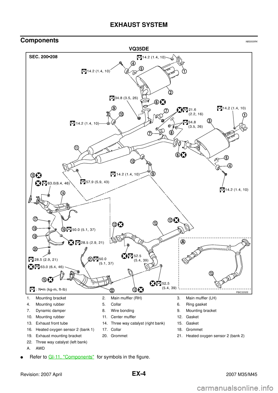
ComponentsNBS005RK
VQ35DE
�Refer to GI-11, "Components" for symbols in the figure.
PBIC3202E
1. Mounting bracket 2. Main muffler (RH) 3. Main muffler (LH)
4. Mounting rubber 5. Collar 6. Ring gasket
7. Dynamic damper 8. Wire bonding 9. Mounting bracket
10. Mounting rubber 11. Center muffler 12. Gasket
13. Exhaust front tube 14. Three way catalyst (right bank) 15. Gasket
16. Heated oxygen sensor 2 (bank 1) 17. Collar 18. Grommet
19. Exhaust mounting bracket 20. Grommet 21. Heated oxygen sensor 2 (bank 2)
22. Three way catalyst (left bank)
A. AWD