Page 3190 of 4647

RECOMMENDED CHEMICAL PRODUCTS AND SEALANTS
GI-47
C
D
E
F
G
H
I
J
K
L
MB
GI
Revision: 2007 April2007 M35/M45
RECOMMENDED CHEMICAL PRODUCTS AND SEALANTSPFP:00000
Recommended Chemical Products and SealantsNAS00084
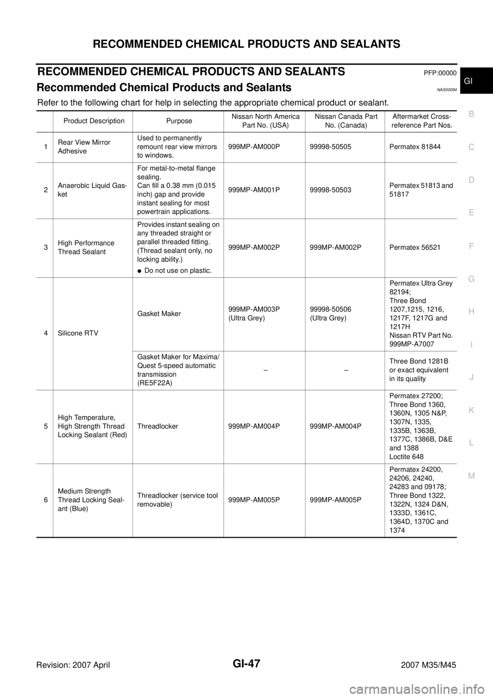
Refer to the following chart for help in selecting the appropriate chemical product or sealant.
Product Description PurposeNissan North America
Part No. (USA)Nissan Canada Part
No. (Canada)Aftermarket Cross-
reference Part Nos.
1Rear View Mirror
AdhesiveUsed to permanently
remount rear view mirrors
to windows.999MP-AM000P 99998-50505 Permatex 81844
2Anaerobic Liquid Gas-
ketFor metal-to-metal flange
sealing.
Can fill a 0.38 mm (0.015
inch) gap and provide
instant sealing for most
powertrain applications.999MP-AM001P 99998-50503Permatex 51813 and
51817
3High Performance
Thread SealantProvides instant sealing on
any threaded straight or
parallel threaded fitting.
(Thread sealant only, no
locking ability.)
�Do not use on plastic.999MP-AM002P 999MP-AM002P Permatex 56521
4 Silicone RTVGasket Maker999MP-AM003P
(Ultra Grey)99998-50506
(Ultra Grey)Permatex Ultra Grey
82194;
Three Bond
1207,1215, 1216,
1217F, 1217G and
1217H
Nissan RTV Part No.
999MP-A7007
Gasket Maker for Maxima/
Quest 5-speed automatic
transmission
(RE5F22A)––Three Bond 1281B
or exact equivalent
in its quality
5High Temperature,
High Strength Thread
Locking Sealant (Red)Threadlocker 999MP-AM004P 999MP-AM004PPermatex 27200;
Three Bond 1360,
1360N, 1305 N&P,
1307N, 1335,
1335B, 1363B,
1377C, 1386B, D&E
and 1388
Loctite 648
6Medium Strength
Thread Locking Seal-
ant (Blue)Threadlocker (service tool
removable)999MP-AM005P 999MP-AM005PPermatex 24200,
24206, 24240,
24283 and 09178;
Three Bond 1322,
1322N, 1324 D&N,
1333D, 1361C,
1364D, 1370C and
1374
Page 3973 of 4647

PR-6
REAR PROPELLER SHAFT
Revision: 2007 April2007 M35/M45
REAR PROPELLER SHAFTPFP:37000
On-Vehicle InspectionNDS000ED
APPEARANCE AND NOISE INSPECTION
�Check the propeller shaft tube surface for dents or cracks. If damaged, replace propeller shaft assembly.
�If center bearing is noisy or damaged, replace center bearing.
PROPELLER SHAFT VIBRATION
If vibration is present at high speed, inspect propeller shaft runout first.
1. Measure propeller shaft runout at runout measuring points by
rotating final drive companion flange with hands. For measuring
point, refer to PR-6, "
Propeller Shaft Runout Measuring Point" .
2. If runout still exceeds specifications, separate propeller shaft at
final drive companion flange; then rotate companion flange 60,
120, 180, 240, 300 degrees and install propeller shaft.
3. Check runout again. If runout still exceeds specifications,
replace propeller shaft assembly.
4. Check the vibration by driving vehicle.
Propeller Shaft Runout Measuring Point
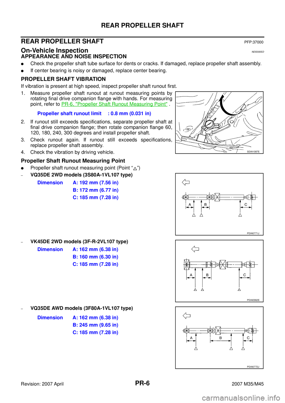
�Propeller shaft runout measuring point (Point “ ”)
–VQ35DE 2WD models (3S80A-1VL107 type)
–VK45DE 2WD models (3F-R-2VL107 type)
–VQ35DE AWD models (3F80A-1VL107 type)Propeller shaft runout limit : 0.8 mm (0.031 in)
SDIA1087E
Dimension A: 192 mm (7.56 in)
B: 172 mm (6.77 in)
C: 185 mm (7.28 in)
PDIA0771J
Dimension A: 162 mm (6.38 in)
B: 160 mm (6.30 in)
C: 185 mm (7.28 in)
PDIA0962E
Dimension A: 162 mm (6.38 in)
B: 245 mm (9.65 in)
C: 185 mm (7.28 in)
PDIA0772J
Page 4073 of 4647
RFD-4
PREPARATION
Revision: 2007 April2007 M35/M45
KV38100800
(J-25604-01)
Attachment
a: 541 mm (21.30 in)
b: 200 mm (7.87 in)Fixing unit assembly
ST3127S000
(J-25765-A)
Preload gauge
1: GG91030000
(J-25765)
Torque wrench
2: HT62940000
(—)
Socket adapter (1/2″)
3: HT62900000
(—)
Socket adapter (3/8″)Measuring pinion bearing preload and total
preload
K V 1 0 1111 0 0
(J-37228)
Seal cutterRemoving rear cover
ST3306S001
(J-22888-D)
Differential side bearing puller set
1: ST33051001
(J-22888-20)
Puller
2: ST33061000
(J-8107-2)
Base
a: 28.5 mm (1.122 in) dia.
b: 38 mm (1.50 in) dia.Removing and installing side bearing inner
race
ST30031000
(J-22912-01)
ReplacerRemoving pinion rear bearing inner race
KV40105230
(—)
Drift
a: 92 mm (3.62 in) dia.
b: 86 mm (3.39 in) dia.
c: 45 mm (1.77 in) dia.Installing pinion rear bearing outer race Tool number
(Kent-Moore No.)
Tool nameDescription
SDIA0267E
NT124
S-NT046
NT072
ZZA0700D
PDIA0591E
Page 4363 of 4647
SE-164
FRONT SEAT
Revision: 2007 April2007 M35/M45
FRONT SEATPFP:87000
Driver's Seat ComponentsNIS0028E
PIIB5328E
Page 4410 of 4647

TROUBLE DIAGNOSIS
SRS-29
C
D
E
F
G
I
J
K
L
MA
B
SRS
Revision: 2007 April2007 M35/M45
DIAGNOSTIC PROCEDURE 4 (CONTINUED FROM DIAGNOSTIC PROCEDURE 2)
Inspecting SRS malfunctioning record
1. CONSIDER POSSIBILITY OF NOT ERASING SELF-DIAGNOSTIC RESULT AFTER REPAIRING
Is it the first time for maintenance of SRS?
YES or NO
YES >> Go to SRS-22, "DIAGNOSTIC PROCEDURE 2" .
NO >> Self-diagnostic result “SELF-DIAG [PAST]” (previously stored in the memory) might not be erased
after repair. Go to SRS-27, "
DIAGNOSTIC PROCEDURE 3" .
DIAGNOSTIC PROCEDURE 5
Inspecting SRS intermittent malfunction by using CONSULT-II — Diagnosis mode
Refer to GI-38, "
CONSULT-II Start Procedure" .
CAUTION:
If CONSULT-II is used with no connection of CONSULT-II CONVERTER, malfunctions might be
detected in self-diagnosis depending on control unit which carry out CAN communication.
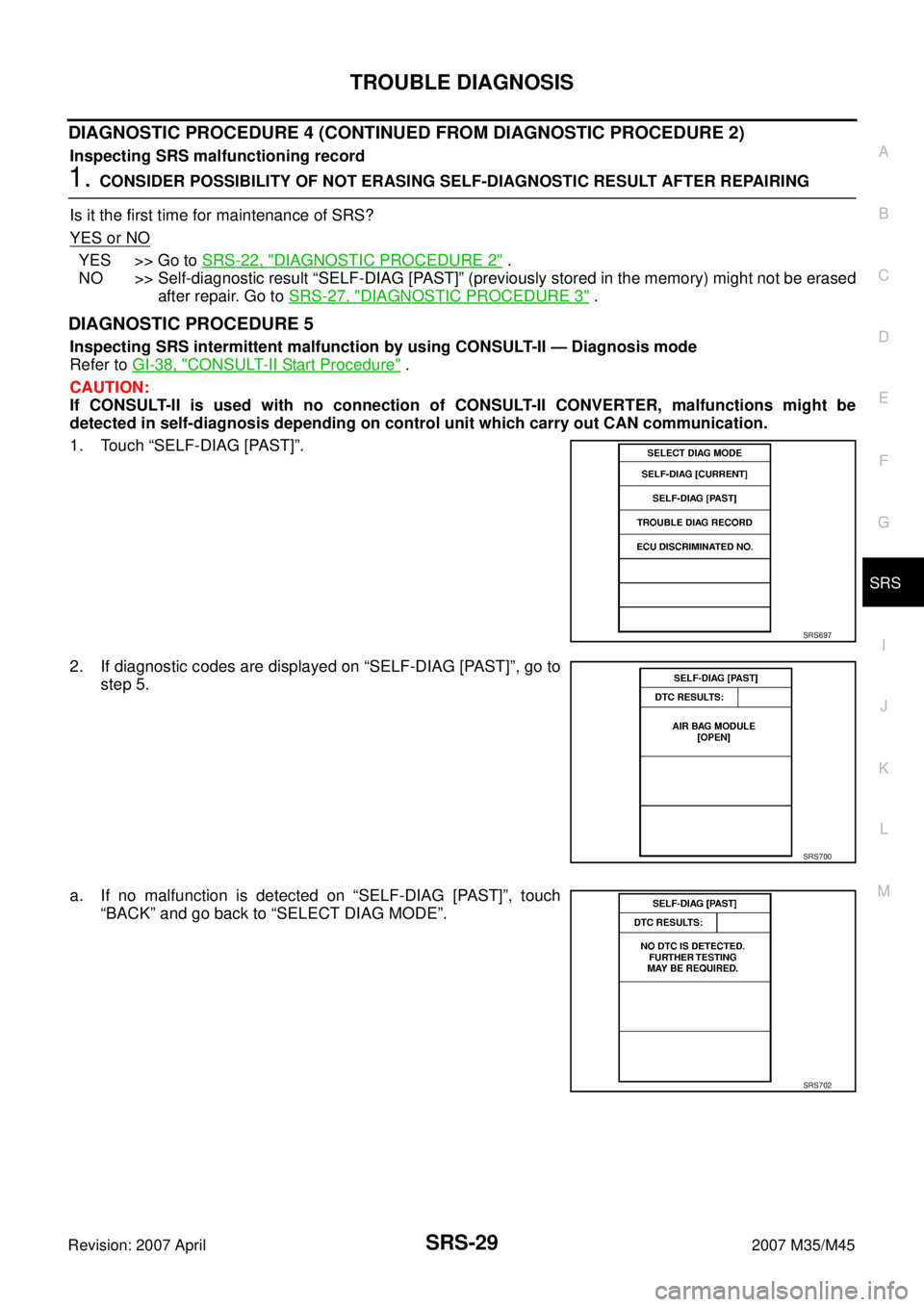
1. Touch “SELF-DIAG [PAST]”.
2. If diagnostic codes are displayed on “SELF-DIAG [PAST]”, go to
step 5.
a. If no malfunction is detected on “SELF-DIAG [PAST]”, touch
“BACK” and go back to “SELECT DIAG MODE”.
SRS697
SRS700
SRS702