Page 3101 of 4647

FL-10
FUEL TANK
Revision: 2007 April2007 M35/M45
FUEL TANKPFP:17202
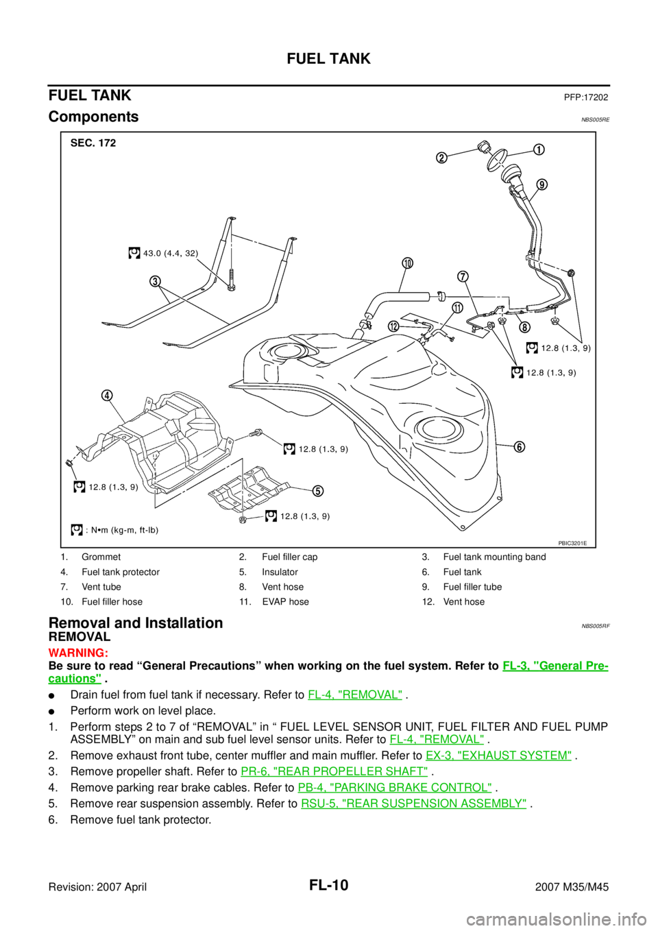
ComponentsNBS005RE
Removal and InstallationNBS005RF
REMOVAL
WARNING:
Be sure to read “General Precautions” when working on the fuel system. Refer to FL-3, "
General Pre-
cautions" .
�Drain fuel from fuel tank if necessary. Refer to FL-4, "REMOVAL" .
�Perform work on level place.
1. Perform steps 2 to 7 of “REMOVAL” in “ FUEL LEVEL SENSOR UNIT, FUEL FILTER AND FUEL PUMP
ASSEMBLY” on main and sub fuel level sensor units. Refer to FL-4, "
REMOVAL" .
2. Remove exhaust front tube, center muffler and main muffler. Refer to EX-3, "
EXHAUST SYSTEM" .
3. Remove propeller shaft. Refer to PR-6, "
REAR PROPELLER SHAFT" .
4. Remove parking rear brake cables. Refer to PB-4, "
PARKING BRAKE CONTROL" .
5. Remove rear suspension assembly. Refer to RSU-5, "
REAR SUSPENSION ASSEMBLY" .
6. Remove fuel tank protector.
1. Grommet 2. Fuel filler cap 3. Fuel tank mounting band
4. Fuel tank protector 5. Insulator 6. Fuel tank
7. Vent tube 8. Vent hose 9. Fuel filler tube
10. Fuel filler hose 11. EVAP hose 12. Vent hose
PBIC3201E
Page 3102 of 4647

FUEL TANK
FL-11
C
D
E
F
G
H
I
J
K
L
MA
FL
Revision: 2007 April2007 M35/M45
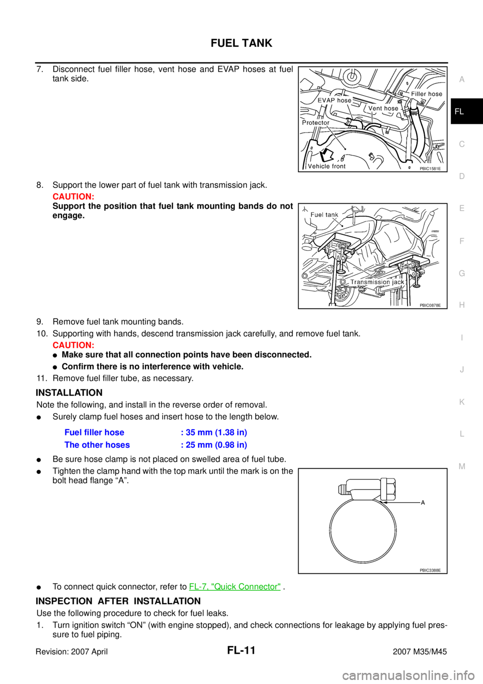
7. Disconnect fuel filler hose, vent hose and EVAP hoses at fuel
tank side.
8. Support the lower part of fuel tank with transmission jack.
CAUTION:
Support the position that fuel tank mounting bands do not
engage.
9. Remove fuel tank mounting bands.
10. Supporting with hands, descend transmission jack carefully, and remove fuel tank.
CAUTION:
�Make sure that all connection points have been disconnected.
�Confirm there is no interference with vehicle.
11. Remove fuel filler tube, as necessary.
INSTALLATION
Note the following, and install in the reverse order of removal.
�Surely clamp fuel hoses and insert hose to the length below.
�Be sure hose clamp is not placed on swelled area of fuel tube.
�Tighten the clamp hand with the top mark until the mark is on the
bolt head flange “A”.
�To connect quick connector, refer to FL-7, "Quick Connector" .
INSPECTION AFTER INSTALLATION
Use the following procedure to check for fuel leaks.
1. Turn ignition switch “ON” (with engine stopped), and check connections for leakage by applying fuel pres-
sure to fuel piping.
PBIC1581E
PBIC0878E
Fuel filler hose : 35 mm (1.38 in)
The other hoses : 25 mm (0.98 in)
PBIC3388E
Page 3103 of 4647
FL-12
FUEL TANK
Revision: 2007 April2007 M35/M45
2. Start engine and rev it up and make sure there are no fuel leaks at the fuel system tube and hose connec-
tions.
�After removing/installing rear suspension assembly, make sure to adjust wheel alignment and then, adjust
neutral position of steering angle sensor. Refer to RSU-5, "
Wheel Alignment Inspection" and BRC-6,
"Adjustment of Steering Angle Sensor Neutral Position" .
Page 3104 of 4647
SERVICE DATA AND SPECIFICATIONS (SDS)
FL-13
C
D
E
F
G
H
I
J
K
L
MA
FL
Revision: 2007 April2007 M35/M45
SERVICE DATA AND SPECIFICATIONS (SDS)PFP:00030
Standard and LimitNBS005RG
FUEL TANK
Fuel tank capacity
Approx. 76 (20-1/8 US gal, 16-3/4 Imp gal)
Fuel recommendation Refer to GI-6
Page 3108 of 4647
PRECAUTIONS
FSU-3
[2WD]
C
D
F
G
H
I
J
K
L
MA
B
FSU
Revision: 2007 April2007 M35/M45
[2WD]PRECAUTIONSPFP:00001
CautionNES000I6
�When installing rubber bushings, the final tightening must be carried out under unladen conditions with
tires on ground. Oil might shorten the life of rubber bushings. Be sure to wipe off any spilled oil.
–Unladen conditions mean that fuel, engine coolant and lubricant are full. Spare tire, jack, hand tools and
mats are in designated positions.
�After servicing suspension parts, be sure to check wheel alignment.
�Self-lock nuts are not reusable. Always use new ones when installing. Since new self-lock nuts are pre-
oiled, tighten as they are.
Page 3111 of 4647
![INFINITI M35 2007 Factory Service Manual FSU-6
[2WD]
FRONT SUSPENSION ASSEMBLY
Revision: 2007 April2007 M35/M45
FRONT SUSPENSION ASSEMBLYPFP:54010
On-Vehicle Inspection NES000IA
Make sure the mounting conditions (looseness, back lash) of eac INFINITI M35 2007 Factory Service Manual FSU-6
[2WD]
FRONT SUSPENSION ASSEMBLY
Revision: 2007 April2007 M35/M45
FRONT SUSPENSION ASSEMBLYPFP:54010
On-Vehicle Inspection NES000IA
Make sure the mounting conditions (looseness, back lash) of eac](/manual-img/42/57024/w960_57024-3110.png)
FSU-6
[2WD]
FRONT SUSPENSION ASSEMBLY
Revision: 2007 April2007 M35/M45
FRONT SUSPENSION ASSEMBLYPFP:54010
On-Vehicle Inspection NES000IA
Make sure the mounting conditions (looseness, back lash) of each component and component conditions
(wear, damage) are normal.
INSPECTION OF UPPER LINK BALL JOINT END PLAY
1. Set front wheels in a straight-ahead position. Do not depress brake pedal.
2. Place an iron bar or similar tool between transverse link and steering knuckle.
3. Measure axial end play by prying it up and down.
CAUTION:
Be careful not to damage ball joint boot. Do not damage the installation position by applying
excessive force.
SHOCK ABSORBER INSPECTION
Check for oil leakage, damage and breakage of installation positions.
Wheel Alignment InspectionNES000IB
DESCRIPTION
Measure wheel alignment under unladen conditions.
NOTE:
“Unladen conditions” means that fuel, engine coolant, and lubricant are full. Spare tire, jack, hand tools and
mats are in designated positions.
PRELIMINARY CHECK
�Check tires for improper air pressure and wear.
�Check road wheels for runout. Refer to WT-6, "ROAD WHEEL" .
�Check wheel bearing axial end play. Refer to FAX-5, "WHEEL BEARING INSPECTION" .
�Check transverse link ball joint axial end play. Refer to FSU-14, "INSPECTION AFTER REMOVAL" .
�Check shock absorber operation.
�Check each mounting part of axle and suspension for looseness and deformation.
�Check each of suspension member, shock absorber, upper link and transverse link for cracks, deforma-
tion and other damage.
�Check vehicle height (posture).
GENERAL INFORMATION AND RECOMMENDATIONS
�A four-wheel thrust alignment should be performed.
–This type of alignment is recommended for any NISSAN/INFINITI vehicle.
–The four-wheel “thrust” process helps ensure that the vehicle is properly aligned and the steering wheel is
centered.
–The alignment rack itself should be capable of accepting any NISSAN/INFINITI vehicle.
–The rack should be checked to ensure that it is level.
�Make sure the machine is properly calibrated.
–Your alignment equipment should be regularly calibrated in order to give correct information.
–Check with the manufacturer of your specific equipment for their recommended Service/Calibration
Schedule.Axial end play : 0 mm (0 in)
Page 3124 of 4647
![INFINITI M35 2007 Factory Service Manual SERVICE DATA AND SPECIFICATIONS (SDS)
FSU-19
[2WD]
C
D
F
G
H
I
J
K
L
MA
B
FSU
Revision: 2007 April2007 M35/M45
SERVICE DATA AND SPECIFICATIONS (SDS)PFP:00030
Wheel Alignment (Unladen *)NES000IJ
*: Fue INFINITI M35 2007 Factory Service Manual SERVICE DATA AND SPECIFICATIONS (SDS)
FSU-19
[2WD]
C
D
F
G
H
I
J
K
L
MA
B
FSU
Revision: 2007 April2007 M35/M45
SERVICE DATA AND SPECIFICATIONS (SDS)PFP:00030
Wheel Alignment (Unladen *)NES000IJ
*: Fue](/manual-img/42/57024/w960_57024-3123.png)
SERVICE DATA AND SPECIFICATIONS (SDS)
FSU-19
[2WD]
C
D
F
G
H
I
J
K
L
MA
B
FSU
Revision: 2007 April2007 M35/M45
SERVICE DATA AND SPECIFICATIONS (SDS)PFP:00030
Wheel Alignment (Unladen *)NES000IJ
*: Fuel, engine coolant and lubricant are full. Spare tire, jack, hand tools and mats are in designated positions.
Ball JointNES000IK
Tire size245/45R18 245/40R19
Camber
Degree minute (Decimal degree)Minimum –1° 00′ (–1.00°)
Nominal –0° 15′ (–0.25°)
Maximum 0° 30′ (0.50°)
Left and right difference 33′ (0.55°) or less
Caster
Degree minute (Decimal degree)Minimum 3° 45′ (3.75°)3° 50′ (3.83°)
Nominal 4° 30′ (4.50°)4° 35′ (4.58°)
Maximum 5° 15′ (5.25°)5° 20′ (5.33°)
Left and right difference 39′ (0.65°) or less
Kingpin inclination
Degree minute (Decimal degree)Minimum 6° 30′ (6.50°)
Nominal 7° 15′ (7.25°)
Maximum 8° 00′ (8.00°)
Total toe-inDistanceMinimum 0 mm (0 in)
Nominal In 1 mm (0.04 in)
Maximum In 2 mm (0.08 in)
Angle (left wheel or right wheel)
Degree minute (Decimal degree)Minimum 0′ (0°)
Nominal In 3′ (0.05°)
Maximum In 6′ (0.10°)
Swing torqueTransverse link 0.5 - 3.6 N·m (0.06 - 0.36 kg-m, 5 - 31 in-lb)
Upper link 0 - 2.0 N·m (0 - 0.2 kg-m, 0 - 17 in-lb)
Measurement on spring balanceTransverse link 7.8 - 56.3 N (0.8 - 5.7 kg, 1.8 - 12.5 lb)
Upper link 0 - 61.5 N (0 - 6.2 kg, 0 - 13.6 lb)
Rotating torqueTransverse link 0.5 - 3.9 N·m (0.06 - 0.39 kg-m, 5 - 34 in-lb)
Upper link 0 - 2.0 N·m (0 - 0.2 kg-m, 0 - 17 in-lb)
Axial end play0 mm (0 in)
Page 3125 of 4647
FSU-20
[2WD]
SERVICE DATA AND SPECIFICATIONS (SDS)
Revision: 2007 April2007 M35/M45
Wheelarch Height (Unladen*)NES000IL
*: Fuel, engine coolant and lubricant are full. Spare tire, jack, hand tools and mats are in designated positions.Tire size 245/45R18 245/40R19
Front (Hf)USA 717 mm (28.23 in)
721 mm (28.39 in)
CANADA 718 mm (28.27 in)
Rear (Hr)USA 710 mm (27.95 in)
711 mm (27.99 in)
CANADA 711 mm (27.99 in)
SFA818A