Page 3653 of 4647

LT-202
FRONT FOG LAMP
Revision: 2007 April2007 M35/M45
Terminals and Reference Values for BCMNKS003R8
CAUTION:
�Check combination switch system terminal waveform under the loaded condition with lighting
switch, turn signal switch and wiper switch OFF not to be fluctuated by overloaded.
�Turn wiper dial position to 4 except when checking waveform or voltage of wiper dial position.
Wiper dial position can be confirmed on CONSULT-II. Refer to LT- 2 3 8 , "
DATA MONITOR" .
Termi-
nal
No.Wire
colorSignal nameMeasuring condition
Reference value
Ignition
switchOperation or condition
3 O/LCombination
switch input 4ONLighting, turn, wiper
switch
(Wiper dial position
4)Front fog lamp switch
ON (Operates only front
fog lamp switch)
Approx. 0.8 V
OFF Approx. 0 V
11 VIgnition switch
(ACC)ACC — Battery voltage
32 LGCombination
switch output 5ONLighting, turn, wiper
switch
(Wiper dial position
4)Front fog lamp switch
ON (Operates only front
fog lamp switch)
Approx. 1.0 V
OFF
Approx. 7.0 - 7.5 V
37 LG Key switch signal OFFIntelligent Key is inserted into key slot. Battery voltage
Intelligent Key is removed from key slot. Approx. 0 V
38 WIgnition switch
(ON) ON — Battery voltage
39 L CAN − H— — —
40 P CAN − L— — —
42 PBattery power
supplyOFF — Battery voltage
52 B Ground ON — Approx. 0 V
55 WBattery power
supplyOFF — Battery voltage
PKIB4955J
PKIB4956J
PKIB4960J
Page 3654 of 4647

FRONT FOG LAMP
LT-203
C
D
E
F
G
H
I
J
L
MA
B
LT
Revision: 2007 April2007 M35/M45
Terminals and Reference Values for IPDM E/RNKS003R9
How to Perform Trouble DiagnosesNKS003RA
1. Confirm the symptom or customer complaint.
2. Understand operation description and function description. Refer to LT- 1 9 4 , "
System Description" .
3. Perform the Preliminary Check. Refer to LT- 2 0 3 , "
Preliminary Check" .
4. Check symptom and repair or replace the cause of malfunction.
5. Does the front fog lamp operate normally? If YES, GO TO 6. If NO, GO TO 4.
6. INSPECTION END
Preliminary CheckNKS003RB
CHECK POWER SUPPLY AND GROUND CIRCUIT
1. CHECK FUSES AND FUSIBLE LINK
Check for blown fuses and fusible link.
62 VFront door switch
driver side signalOFFFront door switch
driver sideON (open) Approx. 0 V
OFF (closed)
Approx. 7.5 - 8.0 V Te r m i -
nal
No.Wire
colorSignal nameMeasuring condition
Reference value
Ignition
switchOperation or condition
PKIB4960J
Te r m i n a l
No.Wire
colorSignal nameMeasuring condition
Reference value
Ignition
switchOperation or condition
36 L/Y Front fog lamp (LH) ONLighting switch must be in
the 2ND position or AUTO
position (headlamp is ON)Front fog lamp switch: OFF Approx. 0 V
Front fog lamp switch: ON Battery voltage
37 W/R Front fog lamp (RH) ONLighting switch must be in
the 2ND position or AUTO
position (headlamp is ON)Front fog lamp switch: OFF Approx. 0 V
Front fog lamp switch: ON Battery voltage
38 B Ground ON — Approx. 0 V
49 L CAN − H— — —
50 P CAN − L— — —
51 B Ground ON — Approx. 0 V
Unit Power source Fuse and fusible link No.
BCMBatteryF
21
Ignition switch ON or START position 1
Ignition switch ACC or ON position 6
IPDM E/R Battery71
88
78
Page 3656 of 4647
NKS003RE
1. CHECK COMBINATION SWITCH INPUT SIGNAL
With CONSULT-II
1. Sel")
FRONT FOG LAMP
LT-205
C
D
E
F
G
H
I
J
L
MA
B
LT
Revision: 2007 April2007 M35/M45
Front Fog Lamps Do Not Illuminate (Both Sides)NKS003RE
1. CHECK COMBINATION SWITCH INPUT SIGNAL
With CONSULT-II
1. Select “BCM” on CONSULT-II. Select “HEAD LAMP” on
“SELECT TEST ITEM” screen.
2. Select “DATA MONITOR” on “SELECT DIAG MODE” screen.
Make sure “FR FOG SW” turns ON-OFF linked with operation of
fog lamp switch.
Without CONSULT-II
Refer to LT- 2 3 9 , "
Combination Switch Inspection" .
OK or NG
OK >> GO TO 2.
NG >> Check combination switch (lighting switch). Refer to LT- 2 3 9 , "
Combination Switch Inspection" .
2. FRONT FOG LAMP ACTIVE TEST
With CONSULT-II
1. Select “IPDM E/R” on CONSULT-II. Select “ACTIVE TEST” on
“SELECT DIAG MODE” screen.
2. Select “LAMPS” on “SELECT TEST ITEM” screen.
3. Touch “FOG” screen.
4. Make sure fog lamp operation.
Without CONSULT-II
1. Start auto active test. Refer to PG-23, "
Auto Active Test" .
2. Make sure fog lamp operation.
OK or NG
OK >> GO TO 3.
NG >> GO TO 4.
3. CHECK IPDM E/R
1. Select “IPDM E/R” on CONSULT-II. Select “DATA MONITOR”
on “SELECT DIAG MODE” screen.
2. Make sure “FR FOG REQ” turns ON when fog lamp switch is in
ON position.
OK or NG
OK >> Replace IPDM E/R. Refer to PG-31, "Removal and
Installation of IPDM E/R" .
NG >> Replace BCM. Refer to BCS-15, "
Removal and Installa-
tion of BCM" . When fog lamp switch is ON : FR FOG SW ON
PKIA7598E
Front fog lamps should operate.
Front fog lamp should operate.
PKIA7748E
When lighting switch is ON
position: FR FOG REQ ON
SKIA5898E
Page 3659 of 4647
NKS003RF
1. CHECK BULB
Check bulb of fog lamp which does not illuminate.
OK or NG
OK >> GO TO 2.
NG")
LT-208
FRONT FOG LAMP
Revision: 2007 April2007 M35/M45
Front Fog Lamp Does Not Illuminate (One Side)NKS003RF
1. CHECK BULB
Check bulb of fog lamp which does not illuminate.
OK or NG
OK >> GO TO 2.
NG >> Replace front fog lamp bulb.
2. CHECK FOG LAMP INPUT SIGNAL
1. Turn ignition switch OFF.
2. Disconnect front fog lamp RH or LH connector.
3. Turn ignition switch ON.
4. Lighting switch is turned 2ND position and fog lamp ON position.
5. Check voltage between front fog lamp RH or LH harness con-
nector and ground.
OK or NG
OK >> GO TO 3.
NG >> GO TO 4.
3. CHECK FRONT FOG LAMP GROUND CIRCUIT
1. Turn ignition switch OFF.
2. Check continuity between front fog lamp RH or LH harness con-
nector and ground.
OK or NG
OK >> Check connecting condition front fog lamp harness con-
nector.
NG >> Repair harness or connector.
Terminal
Voltage
(Approx.) (+)
(-)
Front fog lamp connector Terminal
RH E45 1
Ground Battery voltage
LH E60 1
PKIA6276E
Front fog lamp connector Terminal
Ground Continuity
RH E45 2
Ye s
LH E60 2
PKIA6277E
Page 3660 of 4647

FRONT FOG LAMP
LT-209
C
D
E
F
G
H
I
J
L
MA
B
LT
Revision: 2007 April2007 M35/M45
4. CHECK FOG LAMP CIRCUIT
1. Turn ignition switch OFF.
2. Disconnect IPDM E/R connector.
3. Check continuity between IPDM E/R harness connector (A) and
front fog lamp RH or LH harness connector (B).
4. Check continuity between IPDM E/R harness connector (A) and
ground.
OK or NG
OK >> Replace IPDM E/R. Refer to PG-31, "Removal and Installation of IPDM E/R" .
NG >> Repair harness or connector.
Front Fog Lamps Do Not Turn OFFNKS003RG
1. CHECK FRONT FOG LAMP TURN OFF
Make sure that lighting switch is OFF. And make sure front fog lamp turns off when ignition switch is turned
OFF.
OK or NG
OK >> GO TO 3.
NG >> GO TO 2.
2. CHECK COMBINATION SWITCH INPUT SIGNAL
Select “BCM” on CONSULT-II. With “HEAD LAMP” data monitor,
make sure “FR FOG SW” turns ON-OFF linked with operation of fog
lamp switch.
OK or NG
OK >> Replace IPDM E/R. Refer to PG-31, "Removal and
Installation of IPDM E/R" .
NG >> Check combination switch (lighting switch). Refer to LT-
239, "Combination Switch Inspection" .
CircuitAB
Continuity
Connector Terminal Connector Terminal
RH
E836 E60 1
Ye s
LH 37 E45 1
A
GroundContinuity
Connector Terminal
RH
E836
No
LH 37
SKIB4815E
When fog lamp switch is
OFF position: FR FOG SW OFF
PKIB9378E
Page 3662 of 4647
. Refer to EI-20, \"
FENDER PROT")
FRONT FOG LAMP
LT-211
C
D
E
F
G
H
I
J
L
MA
B
LT
Revision: 2007 April2007 M35/M45
Bulb ReplacementNKS003RI
1. Turn lighting switch OFF.
2. Remove fender protector (front). Refer to EI-20, "
FENDER PROTECTOR" .
3. Turn bulb (1) counterclockwise and unlock it.
4. Disconnect connector (2), and remove bulb (1).
CAUTION:
�Never touch the glass of bulb directly by hand. Keep grease
and other oily matters away from it. Never touch bulb by
hand while it is lit or right after being turned off.
�Never leave bulb out of fog lamp reflector for a long time
because dust, moisture smoke, etc. may affect the perfor-
mance of fog lamp. When replacing bulb, be sure to replace
it with new one.
Removal and InstallationNKS003RJ
REMOVAL
1. Remove front bumper grille (1). Refer to EI-13, "Removal and
Installation of Front Bumper Grille" .
2. Remove screws (2) and remove front fog lamp (3) from vehicle.
: N·m (kg-m, in-lb)
INSTALLATION
Installation is the reverse order of removal.Front fog lamp : 12V - 55W (H11)
SKIB4161E
SKIB4162E
Front fog lamp mounting bolt : 5.5 N·m (0.56 kg-m, 49 in-lb)
Page 3684 of 4647

COMBINATION SWITCH
LT-233
C
D
E
F
G
H
I
J
L
MA
B
LT
Revision: 2007 April2007 M35/M45
Combination Switch Reading FunctionNKS003S6
For details, refer to BCS-3, "COMBINATION SWITCH READING FUNCTION" .
Terminals and Reference Values for BCMNKS003S7
CAUTION:
�Check combination switch system terminal waveform under the loaded condition with lighting
switch, turn signal switch and wiper switch OFF not to be fluctuated by overloaded.
�Turn wiper dial position to 4 except when checking waveform or voltage of wiper dial position.
Wiper dial position can be confirmed on CONSULT-II. Refer to LT- 2 3 8 , "
DATA MONITOR" .
Terminal
No.Wire
colorSignal nameMeasuring condition
Reference value
Ignition
switchOperation or condition
2L/RCombination
switch input 5ONLighting, turn, wiper
switch
(Wiper dial position 4)
Any of several con-
ditions below
�Lighting switch 1ST
�Turn signal switch to
right
�Lighting switch HI
beam (Operates only
HI beam switch)Approx. 1.0 V
Lighting switch 2ND
Approx. 2.0 V
OFF Approx. 0 V
3O/LCombination
switch input 4ONLighting, turn, wiper
switch
(Wiper dial position 4)Front fog lamp switch
ON
Approx. 0.8 V
Any of several con-
ditions below
�Lighting switch 2ND
�Lighting switch
PASSING (Operates
only PASSING switch)
�Turn signal switch to
leftApprox. 1.0 V
OFF Approx. 0 V
PKIB4957J
PKIB4953J
PKIB4955J
PKIB4957J
Page 3686 of 4647
COMBINATION SWITCH
LT-235
C
D
E
F
G
H
I
J
L
MA
B
LT
Revision: 2007 April2007 M35/M45
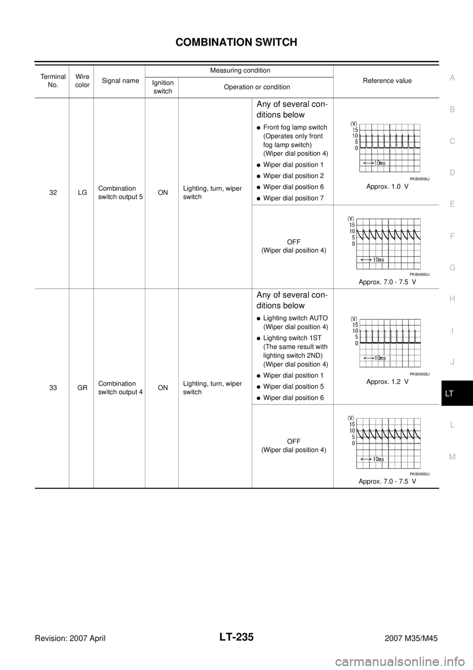
32 LGCombination
switch output 5ONLighting, turn, wiper
switch
Any of several con-
ditions below
�Front fog lamp switch
(Operates only front
fog lamp switch)
(Wiper dial position 4)
�Wiper dial position 1
�Wiper dial position 2
�Wiper dial position 6
�Wiper dial position 7Approx. 1.0 V
OFF
(Wiper dial position 4)
Approx. 7.0 - 7.5 V
33 GRCombination
switch output 4ONLighting, turn, wiper
switch
Any of several con-
ditions below
�Lighting switch AUTO
(Wiper dial position 4)
�Lighting switch 1ST
(The same result with
lighting switch 2ND)
(Wiper dial position 4)
�Wiper dial position 1
�Wiper dial position 5
�Wiper dial position 6Approx. 1.2 V
OFF
(Wiper dial position 4)
Approx. 7.0 - 7.5 V Terminal
No.Wire
colorSignal nameMeasuring condition
Reference value
Ignition
switchOperation or condition
PKIB4956J
PKIB4960J
PKIB4958J
PKIB4960J