Page 3340 of 4647
INSTRUMENT PANEL ASSEMBLY
IP-13
C
D
E
F
G
H
J
K
L
MA
B
IP
Revision: 2007 April2007 M35/M45
13. Remove instrument driver lower panel.
�Remove hood opener mounting bolt. Refer to BL-18,
"Removal and Installation of Hood Lock Control" .
�Pull back.
�Disconnect harness connector.
14. Remove instrument finisher A.
�Insert a remover into upper space.
15. Remove instrument finisher C.
�Insert a remover into upper space
16. Remove cluster lid A
�Pull back.
17. Remove combination meter. Refer to DI-27, "
Removal and Installation of Combination Meter" .
18. Remove steering column cover with power tool.
19. Remove upper ventilator grille.Refer to ATC-143, "
DUCTS AND GRILLES" .
PIIB4112E
PIIB4113E
PIIB4114E
PIIB6503E
Page 3342 of 4647
INSTRUMENT PANEL ASSEMBLY
IP-15
C
D
E
F
G
H
J
K
L
MA
B
IP
Revision: 2007 April2007 M35/M45
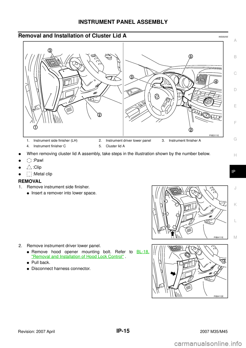
Removal and Installation of Cluster Lid ANIS0025E
�When removing cluster lid A assembly, take steps in the illustration shown by the number below.
� :Pawl
� :Clip
� :Metal clip
REMOVAL
1. Remove instrument side finisher.
�Insert a remover into lower space.
2. Remove instrument driver lower panel.
�Remove hood opener mounting bolt. Refer to BL-18,
"Removal and Installation of Hood Lock Control" .
�Pull back.
�Disconnect harness connector.
1. Instrument side finisher (LH) 2. Instrument driver lower panel 3. Instrument finisher A
4. Instrument finisher C 5. Cluster lid A
P I I B 3 111 E
P I I B 4 111 E
PIIB4112E
Page 3358 of 4647
![INFINITI M35 2007 Factory Service Manual TROUBLE DIAGNOSIS
LAN-11
[CAN FUNDAMENTAL]
C
D
E
F
G
H
I
J
L
MA
B
LAN
Revision: 2007 April2007 M35/M45
Example: CAN-H, CAN-L Harness Short Circuit
SKIB8741E
Unit name Symptom
ECM
�Engine torque limiti](/manual-img/42/57024/w960_57024-3357.png "INFINITI M35 2007 Factory Service Manual TROUBLE DIAGNOSIS
LAN-11
[CAN FUNDAMENTAL]
C
D
E
F
G
H
I
J
L
MA
B
LAN
Revision: 2007 April2007 M35/M45
Example: CAN-H, CAN-L Harness Short Circuit
SKIB8741E
Unit name Symptom
ECM
�Engine torque limiti")
TROUBLE DIAGNOSIS
LAN-11
[CAN FUNDAMENTAL]
C
D
E
F
G
H
I
J
L
MA
B
LAN
Revision: 2007 April2007 M35/M45
Example: CAN-H, CAN-L Harness Short Circuit
SKIB8741E
Unit name Symptom
ECM
�Engine torque limiting is affected, and shift harshness increases.
�Engine speed drops.
BCM
�Reverse warning chime does not sound.
�The front wiper moves under continuous operation mode even though the front
wiper switch being in the intermittent position.
�The room lamp does not turn ON.
�The engine does not start (if an error or malfunction occurs while turning the igni-
tion switch OFF.)
�The steering lock does not release (if an error or malfunction occurs while turning
the ignition switch OFF.)
EPS control unit The steering effort increases.
Combination meter
�The tachometer and the speedometer do not move.
�Warning lamps turn ON.
�Indicator lamps do not turn ON.
ABS actuator and electric unit (control unit) Normal operation.
TCM No impact on operation.
IPDM E/RWhen the ignition switch is ON,
�The headlamps (Lo) turn ON.
�The cooling fan continues to rotate.
Page 3399 of 4647
![INFINITI M35 2007 Factory Service Manual LAN-52
[CAN]
TROUBLE DIAGNOSIS
Revision: 2007 April2007 M35/M45
CAN Communication Signal ChartNKS004FV
Refer to LAN-15, "How to Use CAN Communication Signal Chart" for how to use CAN communication si](/manual-img/42/57024/w960_57024-3398.png "INFINITI M35 2007 Factory Service Manual LAN-52
[CAN]
TROUBLE DIAGNOSIS
Revision: 2007 April2007 M35/M45
CAN Communication Signal ChartNKS004FV
Refer to LAN-15, \"How to Use CAN Communication Signal Chart\" for how to use CAN communication si")
LAN-52
[CAN]
TROUBLE DIAGNOSIS
Revision: 2007 April2007 M35/M45
CAN Communication Signal ChartNKS004FV
Refer to LAN-15, "How to Use CAN Communication Signal Chart" for how to use CAN communication signal
chart.
TYPE 1/TYPE 2/TYPE 3/TYPE 4/TYPE 5/TYPE 6/TYPE 7
NOTE:
Refer to LAN-41, "
Abbreviation List" for the abbreviations of the connecting units.
T: Transmit R: Receive
Signals
ECM
AFS
*1
BCM
LANE
*2
TCM
AV
I-KEY
M&A
STRG
TPMS
RAS
*3
PSB
ADP
ABS
ICC
*4
IPDM-E
A/C compressor request signal TR
Accelerator pedal position signal T R R R
ASCD CRUISE lamp signal T R
ASCD OD cancel request signal T R
ASCD operation signal T R
ASCD SET lamp signal T R
Battery voltage signal T R
Closed throttle position signal T R R
Cooling fan speed request signal TR
Engine coolant temperature signal T R
Engine speed signal T R R R R R R
Engine status signal T R R R
Fuel consumption monitor signal T R R
ICC brake switch signal T R
ICC prohibition signal T R
ICC steering switch signal T R
Malfunctioning indicator lamp signal T R
Power generation command value signal TR
Stop lamp switch signalTR
RT
TR
Wide open throttle position signal T R
AFS OFF indicator signal T R
A/C switch signal R T
ACC signal T R R
Blower fan motor switch signal R T
Buzzer output signalTR
TR
RT
Day time running light request signal T R
Door lock/unlock status signal T R
Door switch signal T R R R R R
Door unlock signal T R
Front fog light request signal T R R
Front wiper request signal T R R
High beam request signal T R R
Page 3400 of 4647
![INFINITI M35 2007 Factory Service Manual TROUBLE DIAGNOSIS
LAN-53
[CAN]
C
D
E
F
G
H
I
J
L
MA
B
LAN
Revision: 2007 April2007 M35/M45
Ignition switch ON signal T R R
Ignition switch signal T R R
Key ID signal T R
Key switch signal T R
Low beam](/manual-img/42/57024/w960_57024-3399.png "INFINITI M35 2007 Factory Service Manual TROUBLE DIAGNOSIS
LAN-53
[CAN]
C
D
E
F
G
H
I
J
L
MA
B
LAN
Revision: 2007 April2007 M35/M45
Ignition switch ON signal T R R
Ignition switch signal T R R
Key ID signal T R
Key switch signal T R
Low beam")
TROUBLE DIAGNOSIS
LAN-53
[CAN]
C
D
E
F
G
H
I
J
L
MA
B
LAN
Revision: 2007 April2007 M35/M45
Ignition switch ON signal T R R
Ignition switch signal T R R
Key ID signal T R
Key switch signal T R
Low beam request signal T R
Oil pressure switch signalTR
RT
Position light request signal T R R
Rear window defogger switch signal T R
Sleep wake up signal T R R R R
Theft warning horn request signal T R
Trunk switch signal T R R
Turn indicator signal T R R
A/T CHECK indicator lamp signal T R
A/T position indicator signal R T R R R
A/T self-diagnosis signal R T
Current gear position signal T R R
Manual mode indicator signal T R R
N range signal T R R
Output shaft revolution signal R R T R
P range signal T R R R R
R range signal T R R R
Turbine revolution signal R T R
A/C switch/indicator signalTR
RT
System setting signalTR R
RT T
Door lock/unlock trunk open request signal R T
Hazard and horn request signal R T
Key warning signal T R
Meter display signalTR
RT
Panic alarm request signal R T
Power window open request signal R T
A/C evaporator temperature signal R T
Distance to empty signal R T
Fuel level low warning signal R T
Fuel level sensor signal R T
Manual mode shift down signal R T
Manual mode shift up signal R T
Manual mode signal R T
Not manual mode signal R T
Parking brake switch signal R TSignals
ECM
AFS
*1
BCM
LANE
*2
TCM
AV
I-KEY
M&A
STRG
TPMS
RAS
*3
PSB
ADP
ABS
ICC
*4
IPDM-E
Page 3402 of 4647
![INFINITI M35 2007 Factory Service Manual TROUBLE DIAGNOSIS
LAN-55
[CAN]
C
D
E
F
G
H
I
J
L
MA
B
LAN
Revision: 2007 April2007 M35/M45
TYPE 8/TYPE 9/TYPE 10/TYPE 11
NOTE:
Refer to LAN-41, "
Abbreviation List" for the abbreviations of the conne](/manual-img/42/57024/w960_57024-3401.png "INFINITI M35 2007 Factory Service Manual TROUBLE DIAGNOSIS
LAN-55
[CAN]
C
D
E
F
G
H
I
J
L
MA
B
LAN
Revision: 2007 April2007 M35/M45
TYPE 8/TYPE 9/TYPE 10/TYPE 11
NOTE:
Refer to LAN-41, \"
Abbreviation List\" for the abbreviations of the conne")
TROUBLE DIAGNOSIS
LAN-55
[CAN]
C
D
E
F
G
H
I
J
L
MA
B
LAN
Revision: 2007 April2007 M35/M45
TYPE 8/TYPE 9/TYPE 10/TYPE 11
NOTE:
Refer to LAN-41, "
Abbreviation List" for the abbreviations of the connecting units.
T: Transmit R: Receive
Signals
ECM
4WD
AFS
*1
BCM
LANE
*2
TCM
AV
I-KEY
M&A
STRG
TPMS
PSB
ADP
ABS
ICC
*3
IPDM-E
A/C compressor request signal TR
Accelerator pedal position signal T R R R R
ASCD CRUISE lamp signal T R
ASCD OD cancel request signal T R
ASCD operation signal T R
ASCD SET lamp signal T R
Battery voltage signal T R
Closed throttle position signal T R R
Cooling fan speed request signal TR
Engine coolant temperature signal T R
Engine speed signal T R R R R R R
Engine status signal T R R R
Fuel consumption monitor signal T R R
ICC brake switch signal T R
ICC prohibition signal T R
ICC steering switch signal T R
Malfunctioning indicator lamp signal T R
Power generation command value signal TR
Snow mode switch signalTRR
RT
Stop lamp switch signalTR
RRT
TR
Wide open throttle position signal T R
AWD signal T R
AWD warning lamp signal T R
AFS OFF indicator signal T R
A/C switch signal R T
ACC signal T R R
Blower fan motor switch signal R T
Buzzer output signalTR
TR
RT
Day time running light request signal T R
Door lock/unlock status signal T R
Door switch signal T R R R R R
Door unlock signal T R
Front fog light request signal T R R
Front wiper request signal T R R
High beam request signal T R R
Page 3403 of 4647
![INFINITI M35 2007 Factory Service Manual LAN-56
[CAN]
TROUBLE DIAGNOSIS
Revision: 2007 April2007 M35/M45
Ignition switch ON signal T R R
Ignition switch signal T R R
Key ID signal T R
Key switch signal T R
Low beam request signal T R
Oil pre](/manual-img/42/57024/w960_57024-3402.png "INFINITI M35 2007 Factory Service Manual LAN-56
[CAN]
TROUBLE DIAGNOSIS
Revision: 2007 April2007 M35/M45
Ignition switch ON signal T R R
Ignition switch signal T R R
Key ID signal T R
Key switch signal T R
Low beam request signal T R
Oil pre")
LAN-56
[CAN]
TROUBLE DIAGNOSIS
Revision: 2007 April2007 M35/M45
Ignition switch ON signal T R R
Ignition switch signal T R R
Key ID signal T R
Key switch signal T R
Low beam request signal T R
Oil pressure switch signalTR
RT
Position light request signal T R R
Rear window defogger switch signal T R
Sleep wake up signal T R R R R
Theft warning horn request signal T R
Trunk switch signal T R R
Turn indicator signal T R R
A/T CHECK indicator lamp signal T R
A/T position indicator signal R T R R R
A/T self-diagnosis signal R T
Current gear position signal T R R
Manual mode indicator signal T R R
N range signal T R R
Output shaft revolution signal R R T R
P range signal T R R R R
R range signal T R R R
Turbine revolution signal R T R
A/C switch/indicator signalTR
RT
System setting signalTR R
RT T
Door lock/unlock trunk open request signal R T
Hazard and horn request signal R T
Key warning signalTR
Meter display signalTR
RT
Panic alarm request signal R T
Power window open request signal R T
A/C evaporator temperature signal R T
Distance to empty signal R T
Fuel level low warning signal R T
Fuel level sensor signal R T
Manual mode shift down signal R T
Manual mode shift up signal R T
Manual mode signal R T
Not manual mode signal R T
Parking brake switch signal R R TSignals
ECM
4WD
AFS
*1
BCM
LANE
*2
TCM
AV
I-KEY
M&A
STRG
TPMS
PSB
ADP
ABS
ICC
*3
IPDM-E
Page 3460 of 4647
 - CONVENTIONAL TYPE -
LT-9
C
D
E
F
G
H
I
J
L
MA
B
LT
Revision: 2007 April2007 M35/M45
OUTLINE
Power is supplied at all times
�to headlamp high relay, located in IPDM E/R and
�to hea")
HEADLAMP (FOR USA) - CONVENTIONAL TYPE -
LT-9
C
D
E
F
G
H
I
J
L
MA
B
LT
Revision: 2007 April2007 M35/M45
OUTLINE
Power is supplied at all times
�to headlamp high relay, located in IPDM E/R and
�to headlamp low relay, located in IPDM E/R, from battery direct,
�through 15A fuse (No. 71, located in IPDM E/R)
�to CPU, located in IPDM E/R,
�through 15A fuse (No. 78, located in IPDM E/R)
�to CPU, located in IPDM E/R,
�through 50A fusible link (letter F, located in fuse and fusible link block)
�to BCM terminal 55,
�through 10A fuse [No. 21, located in fuse block (J/B)]
�to BCM terminal 42 and
�to combination meter terminal 23,
�through 10A fuse [No. 19, located in fuse block (J/B)]
�to unified meter and A/C amp. terminal 54,
�through 10A fuse [No. 22, located in fuse block (J/B)]
�to key slot terminal 1.
When the ignition switch is in the ON or START position, power is supplied
�to CPU, located in IPDM E/R,
�through 15A fuse [No. 1, located in fuse block (J/B)]
�to BCM terminal 38,
�through 10A fuse [No. 14, located in fuse block (J/B)]
�to combination meter terminal 12,
�through 10A fuse [No. 12, located in fuse block (J/B)]
�to unified meter and A/C amp. terminal 53.
When the ignition switch is in the ACC or ON position, power is supplied
�through 10A fuse [No. 6, located in fuse block (J/B)]
�to BCM terminal 11.
Ground is supplied
�to BCM terminal 52
�to combination meter terminals 9, 10, and 11
�to unified meter and A/C amp. terminals 55 and 71
�to push-button ignition switch (push switch) terminal 1
�to key slot terminal 8
�through grounds M16 and M70,
�to IPDM E/R terminals 38 and 51
�through grounds E22 and E43.