Page 3614 of 4647
ACTIVE AFS
LT-163
C
D
E
F
G
H
I
J
L
MA
B
LT
Revision: 2007 April2007 M35/M45
7. CHECK SWIVEL POSITION SENSOR GROUND CIRCUIT
1. Turn ignition switch OFF.
2. Disconnect AFS control unit connector and front combination lamp RH connector.
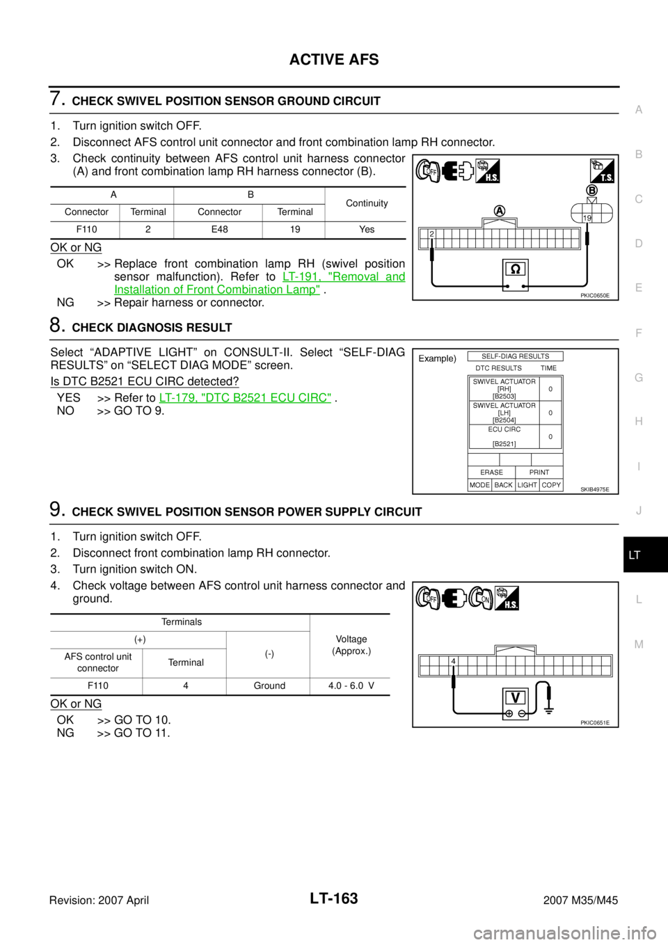
3. Check continuity between AFS control unit harness connector
(A) and front combination lamp RH harness connector (B).
OK or NG
OK >> Replace front combination lamp RH (swivel position
sensor malfunction). Refer to LT- 1 9 1 , "
Removal and
Installation of Front Combination Lamp" .
NG >> Repair harness or connector.
8. CHECK DIAGNOSIS RESULT
Select “ADAPTIVE LIGHT” on CONSULT-II. Select “SELF-DIAG
RESULTS” on “SELECT DIAG MODE” screen.
Is DTC B2521 ECU CIRC detected?
YES >> Refer to LT- 1 7 9 , "DTC B2521 ECU CIRC" .
NO >> GO TO 9.
9. CHECK SWIVEL POSITION SENSOR POWER SUPPLY CIRCUIT
1. Turn ignition switch OFF.
2. Disconnect front combination lamp RH connector.
3. Turn ignition switch ON.
4. Check voltage between AFS control unit harness connector and
ground.
OK or NG
OK >> GO TO 10.
NG >> GO TO 11.
AB
Continuity
Connector Terminal Connector Terminal
F110 2 E48 19 Yes
PKIC0650E
SKIB4975E
Terminals
Voltage
(Approx.) (+)
(-)
AFS control unit
connectorTerminal
F110 4 Ground 4.0 - 6.0 V
PKIC0651E
Page 3617 of 4647
LT-166
ACTIVE AFS
Revision: 2007 April2007 M35/M45
13. CHECK SWIVEL MOTOR CIRCUIT 1
1. Connect front combination lamp RH connector.
2. Turn ignition switch ON.
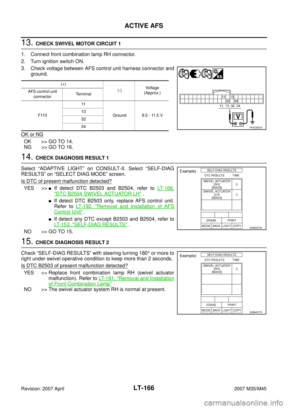
3. Check voltage between AFS control unit harness connector and
ground.
OK or NG
OK >> GO TO 14.
NG >> GO TO 16.
14. CHECK DIAGNOSIS RESULT 1
Select “ADAPTIVE LIGHT” on CONSULT-II. Select “SELF-DIAG
RESULTS” on “SELECT DIAG MODE” screen.
Is DTC of present malfunction detected?
YES >>�If detect DTC B2503 and B2504, refer to LT- 1 6 8 ,
"DTC B2504 SWIVEL ACTUATOR LH" .
�If detect DTC B2503 only, replace AFS control unit.
Refer to LT- 1 9 2 , "
Removal and Installation of AFS
Control Unit" .
�If detect any DTC except B2503 and B2504, refer to
LT- 1 5 3 , "
SELF-DIAG RESULTS" .
NO >> GO TO 15.
15. CHECK DIAGNOSIS RESULT 2
Check “SELF-DIAG RESULTS” with steering turning 180° or more to
right under swivel operative condition to keep more than 2 seconds.
Is DTC B2503 of present malfunction detected?
YES >> Replace front combination lamp RH (swivel actuator
malfunction). Refer to LT- 1 9 1 , "
Removal and Installation
of Front Combination Lamp" .
NO >> The swivel actuator system RH is normal at present.
(+)
(-)Voltage
(Approx.) AFS control unit
connectorTerminal
F11011
Ground 9.5 - 11.5 V 13
32
34
PKIC0657E
SKIB4974E
SKIB4977E
Page 3621 of 4647
LT-170
ACTIVE AFS
Revision: 2007 April2007 M35/M45
7. CHECK SWIVEL POSITION SENSOR GROUND CIRCUIT
1. Turn ignition switch OFF.
2. Disconnect AFS control unit connector and front combination lamp LH connector.
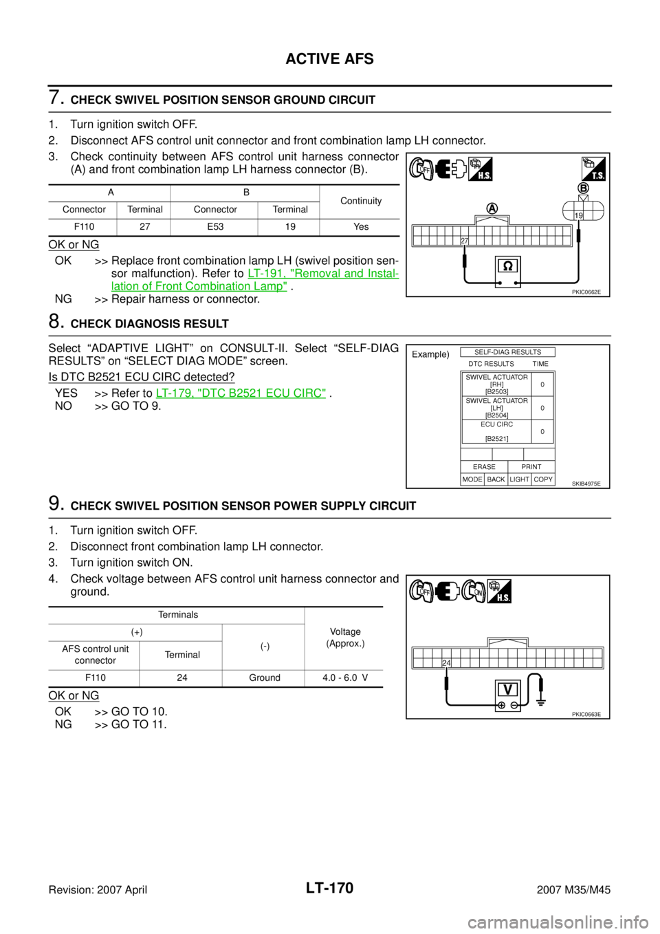
3. Check continuity between AFS control unit harness connector
(A) and front combination lamp LH harness connector (B).
OK or NG
OK >> Replace front combination lamp LH (swivel position sen-
sor malfunction). Refer to LT- 1 9 1 , "
Removal and Instal-
lation of Front Combination Lamp" .
NG >> Repair harness or connector.
8. CHECK DIAGNOSIS RESULT
Select “ADAPTIVE LIGHT” on CONSULT-II. Select “SELF-DIAG
RESULTS” on “SELECT DIAG MODE” screen.
Is DTC B2521 ECU CIRC detected?
YES >> Refer to LT- 1 7 9 , "DTC B2521 ECU CIRC" .
NO >> GO TO 9.
9. CHECK SWIVEL POSITION SENSOR POWER SUPPLY CIRCUIT
1. Turn ignition switch OFF.
2. Disconnect front combination lamp LH connector.
3. Turn ignition switch ON.
4. Check voltage between AFS control unit harness connector and
ground.
OK or NG
OK >> GO TO 10.
NG >> GO TO 11.
AB
Continuity
Connector Terminal Connector Terminal
F110 27 E53 19 Yes
PKIC0662E
SKIB4975E
Te r m i n a l s
Voltage
(Approx.) (+)
(-)
AFS control unit
connectorTerminal
F110 24 Ground 4.0 - 6.0 V
PKIC0663E
Page 3624 of 4647
ACTIVE AFS
LT-173
C
D
E
F
G
H
I
J
L
MA
B
LT
Revision: 2007 April2007 M35/M45
13. CHECK SWIVEL MOTOR CIRCUIT 1
1. Connect front combination lamp LH connector.
2. Turn ignition switch ON.
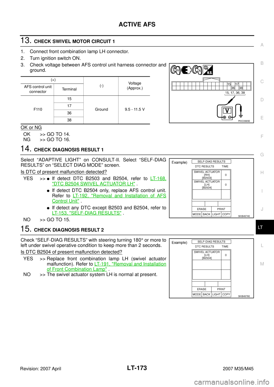
3. Check voltage between AFS control unit harness connector and
ground.
OK or NG
OK >> GO TO 14.
NG >> GO TO 16.
14. CHECK DIAGNOSIS RESULT 1
Select “ADAPTIVE LIGHT” on CONSULT-II. Select “SELF-DIAG
RESULTS” on “SELECT DIAG MODE” screen.
Is DTC of present malfunction detected?
YES >>�If detect DTC B2503 and B2504, refer to LT- 1 6 8 ,
"DTC B2504 SWIVEL ACTUATOR LH" .
�If detect DTC B2504 only, replace AFS control unit.
Refer to LT- 1 9 2 , "
Removal and Installation of AFS
Control Unit" .
�If detect any DTC except B2503 and B2504, refer to
LT- 1 5 3 , "
SELF-DIAG RESULTS" .
NO >> GO TO 15.
15. CHECK DIAGNOSIS RESULT 2
Check “SELF-DIAG RESULTS” with steering turning 180° or more to
left under swivel operative condition to keep more than 2 seconds.
Is DTC B2504 of present malfunction detected?
YES >> Replace front combination lamp LH (swivel actuator
malfunction). Refer to LT- 1 9 1 , "
Removal and Installation
of Front Combination Lamp" .
NO >> The swivel actuator system LH is normal at present.
(+)
(-)Voltage
(Approx.) AFS control unit
connectorTerminal
F11015
Ground 9.5 - 11.5 V 17
36
38
PKIC0665E
SKIB4974E
SKIB4976E
Page 3626 of 4647
ACTIVE AFS
LT-175
C
D
E
F
G
H
I
J
L
MA
B
LT
Revision: 2007 April2007 M35/M45
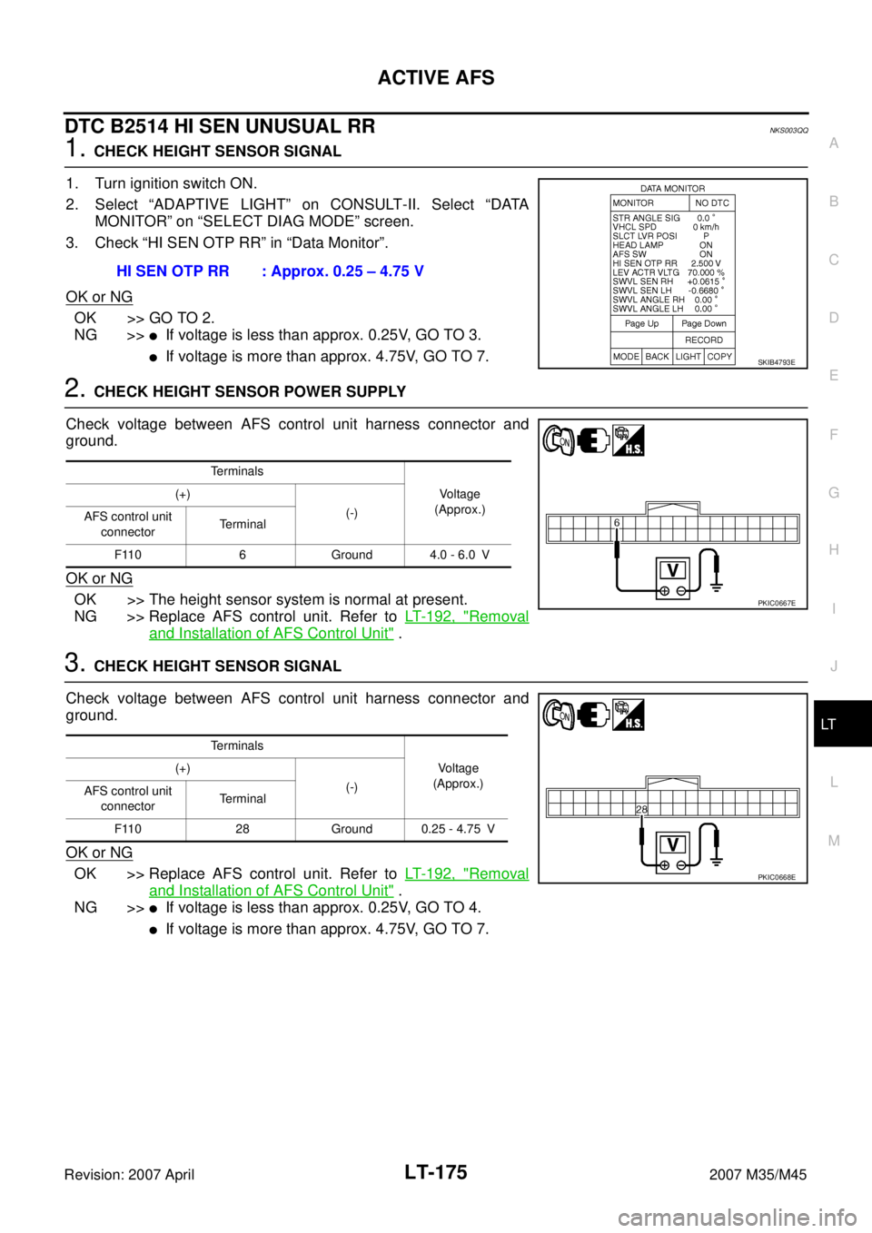
DTC B2514 HI SEN UNUSUAL RRNKS003QQ
1. CHECK HEIGHT SENSOR SIGNAL
1. Turn ignition switch ON.
2. Select “ADAPTIVE LIGHT” on CONSULT-II. Select “DATA
MONITOR” on “SELECT DIAG MODE” screen.
3. Check “HI SEN OTP RR” in “Data Monitor”.
OK or NG
OK >> GO TO 2.
NG >>
�If voltage is less than approx. 0.25V, GO TO 3.
�If voltage is more than approx. 4.75V, GO TO 7.
2. CHECK HEIGHT SENSOR POWER SUPPLY
Check voltage between AFS control unit harness connector and
ground.
OK or NG
OK >> The height sensor system is normal at present.
NG >> Replace AFS control unit. Refer to LT- 1 9 2 , "
Removal
and Installation of AFS Control Unit" .
3. CHECK HEIGHT SENSOR SIGNAL
Check voltage between AFS control unit harness connector and
ground.
OK or NG
OK >> Replace AFS control unit. Refer to LT- 1 9 2 , "Removal
and Installation of AFS Control Unit" .
NG >>
�If voltage is less than approx. 0.25V, GO TO 4.
�If voltage is more than approx. 4.75V, GO TO 7. HI SEN OTP RR : Approx. 0.25 – 4.75 V
SKIB4793E
Terminals
Voltage
(Approx.) (+)
(-)
AFS control unit
connectorTerminal
F110 6 Ground 4.0 - 6.0 V
PKIC0667E
Terminals
Voltage
(Approx.) (+)
(-)
AFS control unit
connectorTerminal
F110 28 Ground 0.25 - 4.75 V
PKIC0668E
Page 3628 of 4647
ACTIVE AFS
LT-177
C
D
E
F
G
H
I
J
L
MA
B
LT
Revision: 2007 April2007 M35/M45
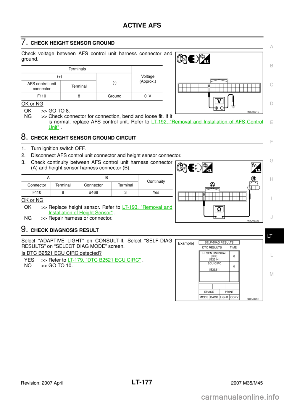
7. CHECK HEIGHT SENSOR GROUND
Check voltage between AFS control unit harness connector and
ground.
OK or NG
OK >> GO TO 8.
NG >> Check connector for connection, bend and loose fit. If it
is normal, replace AFS control unit. Refer to LT- 1 9 2 , "
Removal and Installation of AFS Control
Unit" .
8. CHECK HEIGHT SENSOR GROUND CIRCUIT
1. Turn ignition switch OFF.
2. Disconnect AFS control unit connector and height sensor connector.
3. Check continuity between AFS control unit harness connector
(A) and height sensor harness connector (B).
OK or NG
OK >> Replace height sensor. Refer to LT- 1 9 3 , "Removal and
Installation of Height Sensor" .
NG >> Repair harness or connector.
9. CHECK DIAGNOSIS RESULT
Select “ADAPTIVE LIGHT” on CONSULT-II. Select “SELF-DIAG
RESULTS” on “SELECT DIAG MODE” screen.
Is DTC B2521 ECU CIRC detected?
YES >> Refer to LT- 1 7 9 , "DTC B2521 ECU CIRC" .
NO >> GO TO 10.
Terminals
Voltage
(Approx.) (+)
(-)
AFS control unit
connectorTerminal
F110 8 Ground 0 V
PKIC0671E
AB
Continuity
Connector Terminal Connector Terminal
F110 8 B468 3 Yes
PKIC0672E
SKIB4973E
Page 3633 of 4647
LT-182
ACTIVE AFS
Revision: 2007 April2007 M35/M45
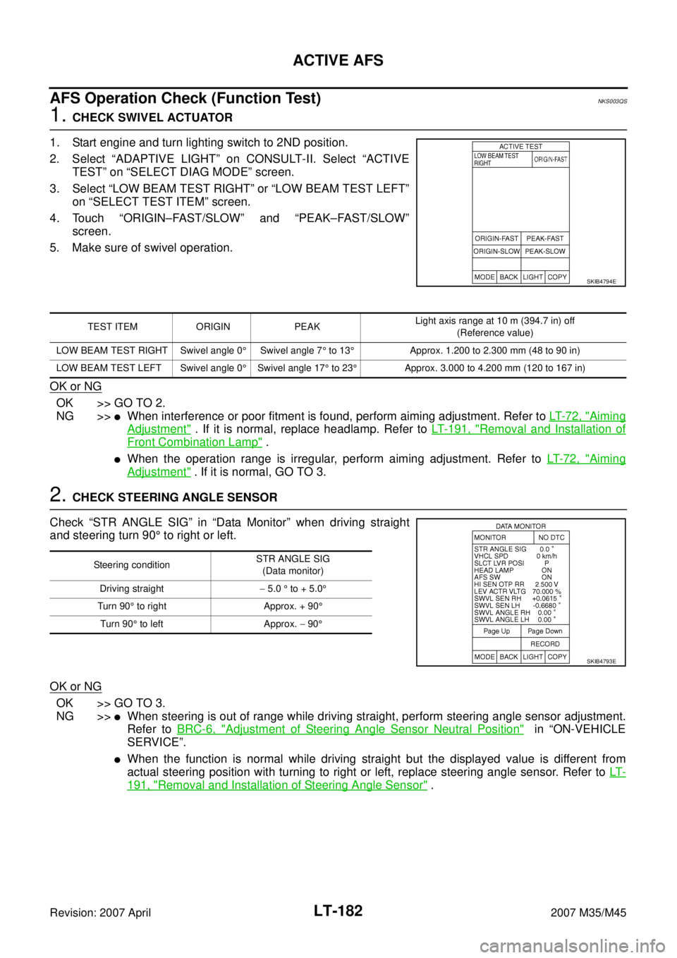
AFS Operation Check (Function Test)NKS003QS
1. CHECK SWIVEL ACTUATOR
1. Start engine and turn lighting switch to 2ND position.
2. Select “ADAPTIVE LIGHT” on CONSULT-II. Select “ACTIVE
TEST” on “SELECT DIAG MODE” screen.
3. Select “LOW BEAM TEST RIGHT” or “LOW BEAM TEST LEFT”
on “SELECT TEST ITEM” screen.
4. Touch “ORIGIN–FAST/SLOW” and “PEAK–FAST/SLOW”
screen.
5. Make sure of swivel operation.
OK or NG
OK >> GO TO 2.
NG >>
�When interference or poor fitment is found, perform aiming adjustment. Refer to LT- 7 2 , "Aiming
Adjustment" . If it is normal, replace headlamp. Refer to LT- 1 9 1 , "Removal and Installation of
Front Combination Lamp" .
�When the operation range is irregular, perform aiming adjustment. Refer to LT- 7 2 , "Aiming
Adjustment" . If it is normal, GO TO 3.
2. CHECK STEERING ANGLE SENSOR
Check “STR ANGLE SIG” in “Data Monitor” when driving straight
and steering turn 90° to right or left.
OK or NG
OK >> GO TO 3.
NG >>
�When steering is out of range while driving straight, perform steering angle sensor adjustment.
Refer to BRC-6, "
Adjustment of Steering Angle Sensor Neutral Position" in “ON-VEHICLE
SERVICE”.
�When the function is normal while driving straight but the displayed value is different from
actual steering position with turning to right or left, replace steering angle sensor. Refer to LT-
191, "Removal and Installation of Steering Angle Sensor" .
SKIB4794E
TEST ITEM ORIGIN PEAKLight axis range at 10 m (394.7 in) off
(Reference value)
LOW BEAM TEST RIGHT Swivel angle 0°Swivel angle 7° to 13°Approx. 1.200 to 2.300 mm (48 to 90 in)
LOW BEAM TEST LEFT Swivel angle 0°Swivel angle 17° to 23°Approx. 3.000 to 4.200 mm (120 to 167 in)
Steering conditionSTR ANGLE SIG
(Data monitor)
Driving straight− 5.0 ° to + 5.0°
Turn 90° to right Approx. + 90°
Turn 90° to left Approx. − 90°
SKIB4793E
Page 3634 of 4647
ACTIVE AFS
LT-183
C
D
E
F
G
H
I
J
L
MA
B
LT
Revision: 2007 April2007 M35/M45
3. CHECK SWIVEL ACTUATOR AND AFS CONTROL UNIT
Check “SWVL SEN RH/LH” and “SWVL ANGLE RH/LH” in “Data
Monitor” with steering turning to right or left under swivel operative
condition.
NOTE:
The angle can be slightly different between the displayed value on “SWVL SEN” and
that on “SWVL ANGLE” even when AFS operation is normal.
OK or NG
OK >> AFS function is normal.
NG >>
�When the difference is 4.5° or more between the displayed value on “SWVL ANGLE” and that
on “SWVL SEN”, replace headlamp.
�When the displayed angle on “SWVL ANGLE” is irregular, replace AFS control unit.
TEST ITEM Turn 180° or more to left Turn 180° or more to right
�SWVL SEN RH
�SWVL ANGLE RHApprox. 0° 7° to 13°
�SWVL SEN LH
�SWVL ANGLE LH 17° to 23°Approx. 0°
SKIB4793E