Page 1036 of 4647

INTELLIGENT KEY SYSTEM
BL-103
C
D
E
F
G
H
J
K
L
MA
B
BL
Revision: 2007 April2007 M35/M45
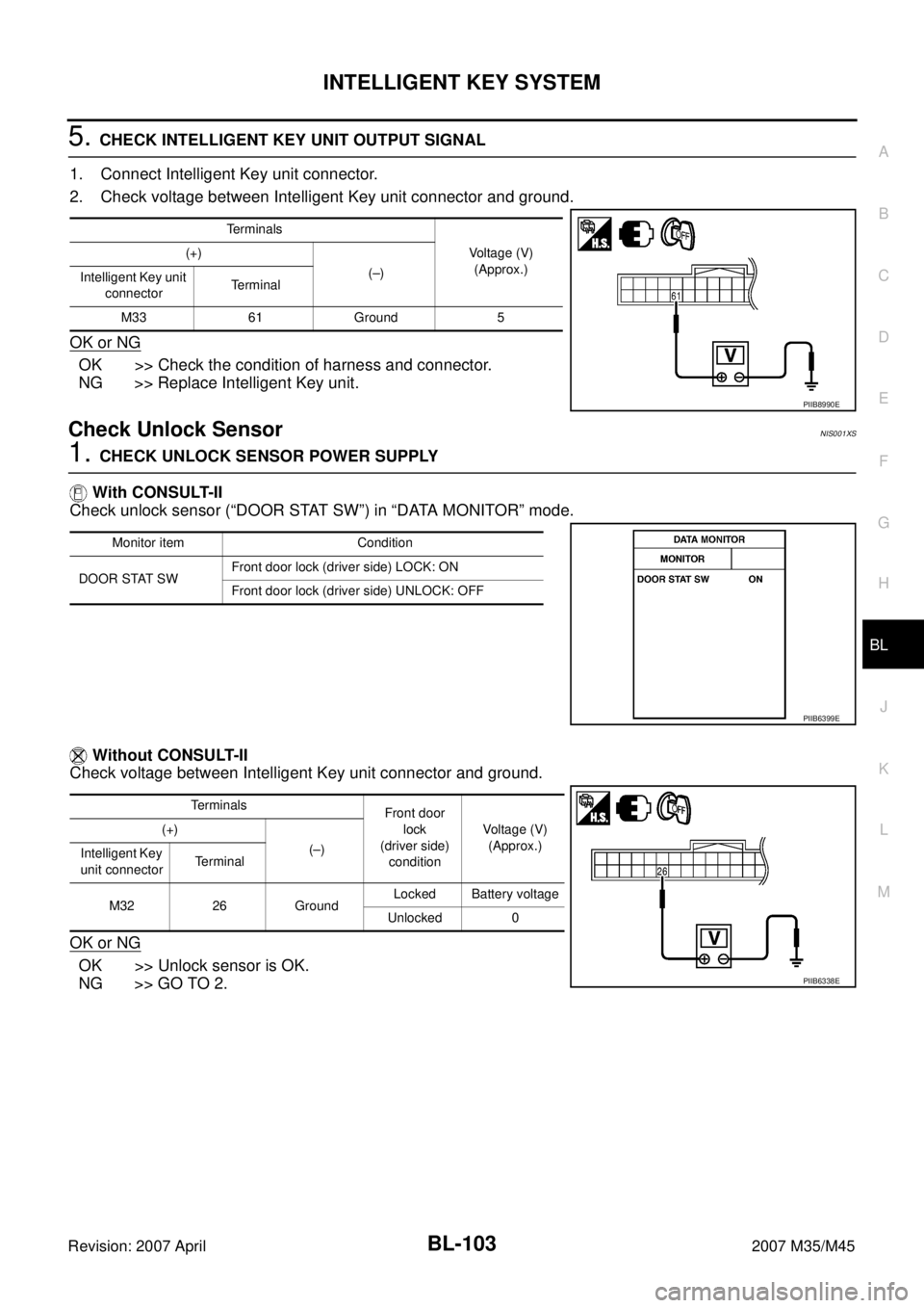
5. CHECK INTELLIGENT KEY UNIT OUTPUT SIGNAL
1. Connect Intelligent Key unit connector.
2. Check voltage between Intelligent Key unit connector and ground.
OK or NG
OK >> Check the condition of harness and connector.
NG >> Replace Intelligent Key unit.
Check Unlock SensorNIS001XS
1. CHECK UNLOCK SENSOR POWER SUPPLY
With CONSULT-II
Check unlock sensor (“DOOR STAT SW”) in “DATA MONITOR” mode.
Without CONSULT-II
Check voltage between Intelligent Key unit connector and ground.
OK or NG
OK >> Unlock sensor is OK.
NG >> GO TO 2.
Terminals
Voltage (V)
(Approx.) (+)
(–)
Intelligent Key unit
connectorTerminal
M33 61 Ground 5
PIIB8990E
Monitor item Condition
DOOR STAT SWFront door lock (driver side) LOCK: ON
Front door lock (driver side) UNLOCK: OFF
PIIB6399E
Terminals
Front door
lock
(driver side)
conditionVoltage (V)
(Approx.) (+)
(–)
Intelligent Key
unit connectorTerminal
M32 26 GroundLocked Battery voltage
Unlocked 0
PIIB6338E
Page 1037 of 4647

BL-104
INTELLIGENT KEY SYSTEM
Revision: 2007 April2007 M35/M45
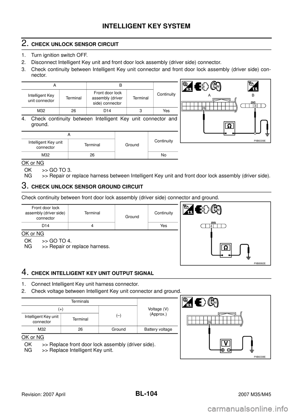
2. CHECK UNLOCK SENSOR CIRCUIT
1. Turn ignition switch OFF.
2. Disconnect Intelligent Key unit and front door lock assembly (driver side) connector.
3. Check continuity between Intelligent Key unit connector and front door lock assembly (driver side) con-
nector.
4. Check continuity between Intelligent Key unit connector and
ground.
OK or NG
OK >> GO TO 3.
NG >> Repair or replace harness between Intelligent Key unit and front door lock assembly (driver side).
3. CHECK UNLOCK SENSOR GROUND CIRCUIT
Check continuity between front door lock assembly (driver side) connector and ground.
OK or NG
OK >> GO TO 4.
NG >> Repair or replace harness.
4. CHECK INTELLIGENT KEY UNIT OUTPUT SIGNAL
1. Connect Intelligent Key unit harness connector.
2. Check voltage between Intelligent Key unit connector and ground.
OK or NG
OK >> Replace front door lock assembly (driver side).
NG >> Replace Intelligent Key unit.
AB
Continuity
Intelligent Key
unit connectorTe r m i n a l Front door lock
assembly (driver
side) connectorTerminal
M32 26 D14 3 Yes
A
GroundContinuity
Intelligent Key unit
connectorTerminal
M32 26 No
PIIB6339E
Front door lock
assembly (driver side)
connectorTerminal
GroundContinuity
D14 4 Yes
PIIB8992E
Terminals
Voltage (V)
(Approx.) (+)
(–)
Intelligent Key unit
connectorTerminal
M32 26 Ground Battery voltage
PIIB6338E
Page 1040 of 4647

INTELLIGENT KEY SYSTEM
BL-107
C
D
E
F
G
H
J
K
L
MA
B
BL
Revision: 2007 April2007 M35/M45
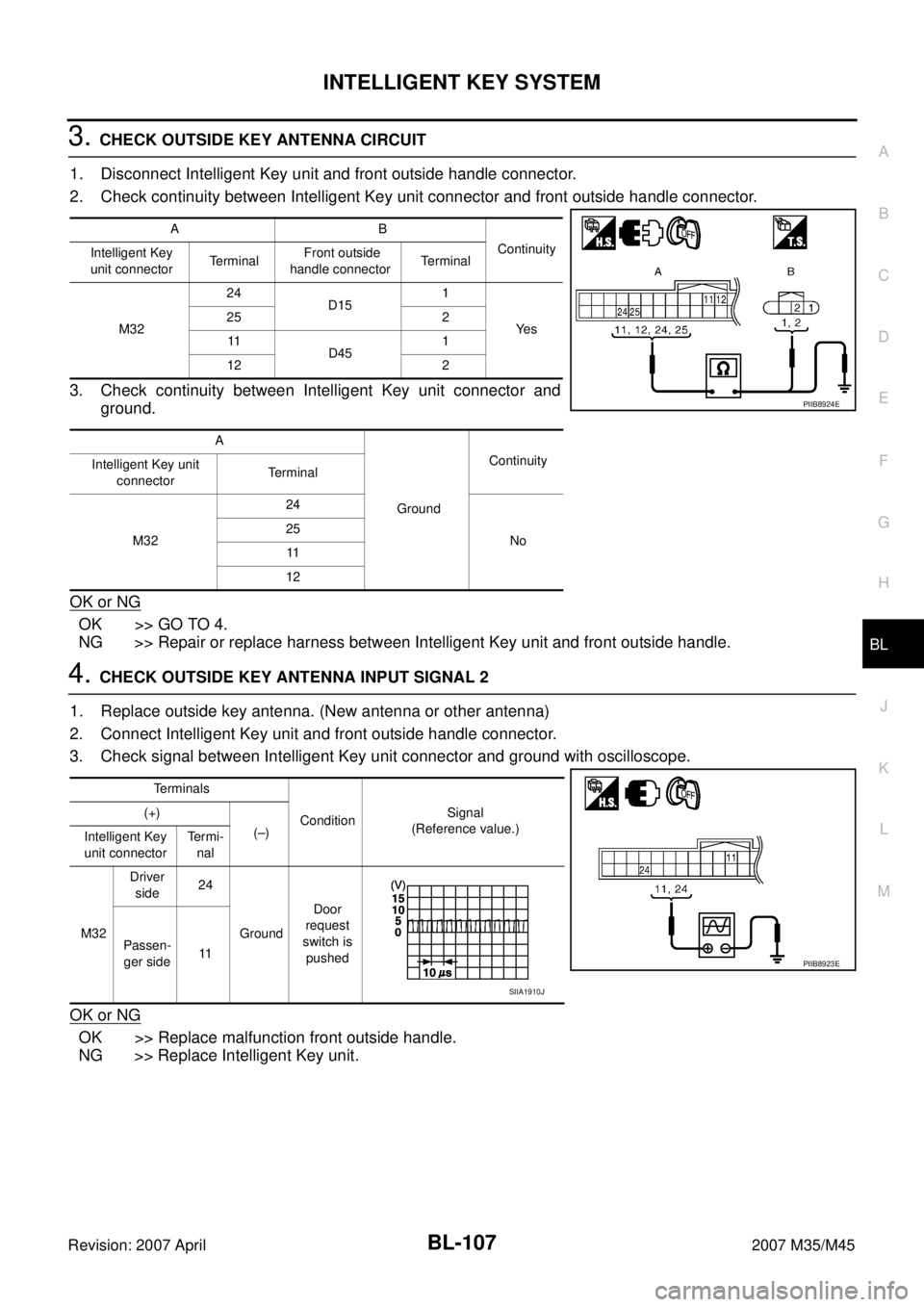
3. CHECK OUTSIDE KEY ANTENNA CIRCUIT
1. Disconnect Intelligent Key unit and front outside handle connector.
2. Check continuity between Intelligent Key unit connector and front outside handle connector.
3. Check continuity between Intelligent Key unit connector and
ground.
OK or NG
OK >> GO TO 4.
NG >> Repair or replace harness between Intelligent Key unit and front outside handle.
4. CHECK OUTSIDE KEY ANTENNA INPUT SIGNAL 2
1. Replace outside key antenna. (New antenna or other antenna)
2. Connect Intelligent Key unit and front outside handle connector.
3. Check signal between Intelligent Key unit connector and ground with oscilloscope.
OK or NG
OK >> Replace malfunction front outside handle.
NG >> Replace Intelligent Key unit.
AB
Continuity
Intelligent Key
unit connectorTerminal Front outside
handle connectorTerminal
M3224
D151
Ye s 25 2
11
D451
12 2
A
GroundContinuity
Intelligent Key unit
connectorTerminal
M3224
No 25
11
12
PIIB8924E
Terminals
ConditionSignal
(Reference value.) (+)
(–)
Intelligent Key
unit connectorTe r m i -
nal
M32Driver
side24
GroundDoor
request
switch is
pushed Passen-
ger side11
PIIB8923E
SIIA1910J
Page 1085 of 4647
![INFINITI M35 2007 Factory Service Manual BL-152
INTELLIGENT KEY SYSTEM/ENGINE START FUNCTION
Revision: 2007 April2007 M35/M45
*: Select “SELECTION FROM MENU”.
WORK SUPPORT
DOOR SW DR*Indicates [OPEN/CLOSE] condition of front door switch INFINITI M35 2007 Factory Service Manual BL-152
INTELLIGENT KEY SYSTEM/ENGINE START FUNCTION
Revision: 2007 April2007 M35/M45
*: Select “SELECTION FROM MENU”.
WORK SUPPORT
DOOR SW DR*Indicates [OPEN/CLOSE] condition of front door switch](/manual-img/42/57024/w960_57024-1084.png)
BL-152
INTELLIGENT KEY SYSTEM/ENGINE START FUNCTION
Revision: 2007 April2007 M35/M45
*: Select “SELECTION FROM MENU”.
WORK SUPPORT
DOOR SW DR*Indicates [OPEN/CLOSE] condition of front door switch driver side from BCM via CAN communica-
tion line.
DOOR SW AS*Indicates [OPEN/CLOSE] condition of front door switch passenger side from BCM via CAN commu-
nication line.
DOOR SW RR* Indicates [OPEN/CLOSE] condition of rear door switch LH from BCM via CAN communication line.
DOOR SW RL* Indicates [OPEN/CLOSE] condition of rear door switch RH from BCM via CAN communication line.
DOOR BK SW* Indicates [OPEN/CLOSE] condition of back door switch from BCM via CAN communication line.
TRUNK SW*Indicates [OPEN/CLOSE] condition of trunk room lamp switch from BCM via CAN communication
line.
VEHICLE SPEED* Indicates [km/h] condition of vehicle speed.Monitor item Content
Monitor item Description
CONFIRM KEY FOB ID It can be checked whether Intelligent Key ID code is registered or not in this mode.
TAKE OUT FROM WINDOW
WARNTake away warning chime (from window) mode can be changed to operate (ON) or not operate
(OFF) with this mode. The operation mode will be changed when “CHANGE SETT” on CON-
SULT-II screen is touched.
LOW BAT OF KEY FOB WARNIntelligent Key low battery warning mode can be changed to operate (ON) or not operate (OFF)
with this mode. The operation mode will be changed when “CHANGE SETT” on CONSULT-II
screen is touched.
ANSWER BACK FUNCTIONHazard and buzzer reminder function mode can be changed to operate (ON) or not operate
(OFF) with this mode. The operation mode will be changed when “CHANGE SETT” on CON-
SULT-II screen is touched.
SELECTIVE UNLOCK FUNC-
TIONSelective unlock function mode can be changed to operate (ON) or not operate (OFF) with this
mode. The operation mode will be changed when “CHANGE SETT” on CONSULT-II screen is
touched.
ANTI KEY LOCK IN FUNCTIONKey reminder function mode can be changed to operate (ON) or not operate (OFF) with this
mode. The operation mode will be changed when “CHANGE SETT” on CONSULT-II screen is
touched.
HORN WITH KEYLESS LOCKHorn reminder function mode by Intelligent Key button can be changed to operate (ON) or not
operate (OFF) with this mode. The operation mode will be changed when “CHANGE SETT” on
CONSULT-II screen is touched.
HAZARD ANSWER BACKHazard reminder function mode can be selected from the following with this mode. The operation
mode will be changed when “CHANGE SETT” on CONSULT-II screen is touched.
�LOCK ONLY: Door lock operation only
�UNLOCK ONLY: Door unlock operation only
�LOCK/UNLOCK: Lock/Unlock operation
�OFF: Non-operation
ANSWER BACK WITH I-KEY
LOCKBuzzer reminder function (lock operation) mode by door request switch (driver side and passen-
ger side) can be selected from the following with this mode. The operation mode will be changed
when “CHANGE SETT” on CONSULT-II screen is touched.
�HORN CHIRP: Sound horn
�BUZZER: Sound Intelligent Key warning buzzer
�OFF: Non-operation
ANSWER BACK WITH I-KEY
UNLOCKBuzzer reminder function (unlock operation) mode by door request switch can be changed to
operate (ON) or not operate (OFF) with this mode.
AUTO RELOCK TIMERAuto door lock timer mode can select the following with this mode.
�1 min
�5 min
�OFF: Non-operation
Page 1121 of 4647
BL-188
DOOR
Revision: 2007 April2007 M35/M45
DOORPFP:80100
Fitting AdjustmentNIS001Z9
FRONT DOOR
Longitudinal Clearance and Surface Height Adjustment At Front End
Loosen the hinge mounting bolts. Raise the front door at rear end to adjust.
REAR DOOR
Longitudinal Clearance and Surface Height Adjustment At Front End
1. Remove the center pillar upper garnish and center pillar lower garnish. Refer to EI-37, "Removal and
Installation" .
1. Front fender 2. Front door outer 3. Rear door outer
4. Rear fender
PIIB5805E
Page 1122 of 4647

DOOR
BL-189
C
D
E
F
G
H
J
K
L
MA
B
BL
Revision: 2007 April2007 M35/M45
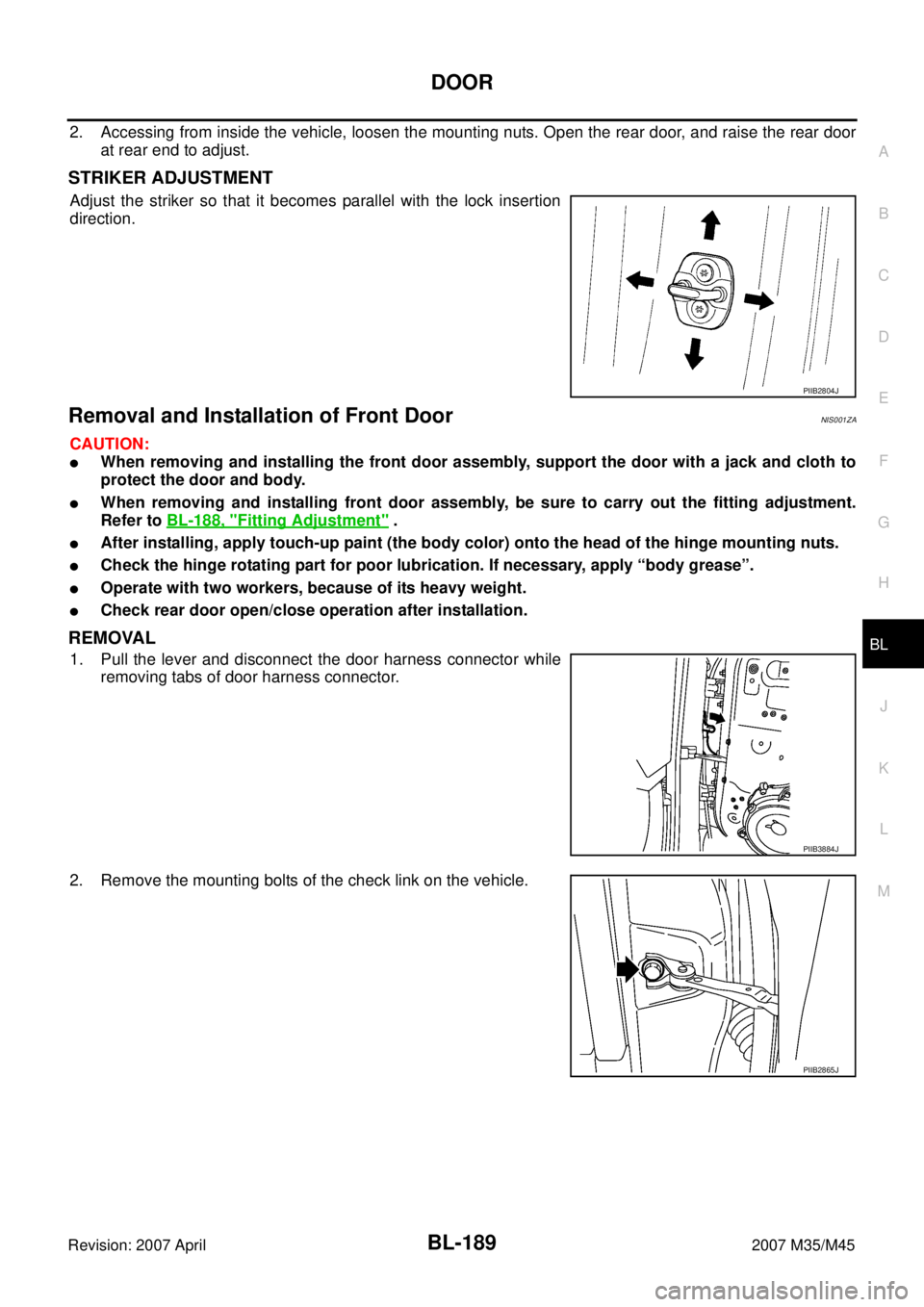
2. Accessing from inside the vehicle, loosen the mounting nuts. Open the rear door, and raise the rear door
at rear end to adjust.
STRIKER ADJUSTMENT
Adjust the striker so that it becomes parallel with the lock insertion
direction.
Removal and Installation of Front DoorNIS001ZA
CAUTION:
�When removing and installing the front door assembly, support the door with a jack and cloth to
protect the door and body.
�When removing and installing front door assembly, be sure to carry out the fitting adjustment.
Refer to BL-188, "
Fitting Adjustment" .
�After installing, apply touch-up paint (the body color) onto the head of the hinge mounting nuts.
�Check the hinge rotating part for poor lubrication. If necessary, apply “body grease”.
�Operate with two workers, because of its heavy weight.
�Check rear door open/close operation after installation.
REMOVAL
1. Pull the lever and disconnect the door harness connector while
removing tabs of door harness connector.
2. Remove the mounting bolts of the check link on the vehicle.
PIIB2804J
PIIB3884J
PIIB2865J
Page 1125 of 4647
BL-192
DOOR
Revision: 2007 April2007 M35/M45
Door WeatherstripNIS001ZC
FRONT DOOR
REMOVAL
1. Remove the mounting bolts of the check link on the vehicle. Refer to BL-189, "Removal and Installation of
Front Door" or BL-190, "Removal and Installation of Rear Door" .
2. Remove the weatherstrip clips and remove weatherstrip.
CAUTION:
After removal, do not pull strongly on the weatherstrip.
INSTALLATION
Install in the reverse order of removal.
Install the door weatherstrip (A) and along the arrow direction.
1. Door weatherstrip 2. Front door 3. Door sash molding
PIIB3878J
Page 1126 of 4647
DOOR
BL-193
C
D
E
F
G
H
J
K
L
MA
B
BL
Revision: 2007 April2007 M35/M45
REAR DOOR
REMOVAL
1. Remove the mounting bolts of the check link on the vehicle. Refer to BL-189, "Removal and Installation of
Front Door" or BL-190, "Removal and Installation of Rear Door" .
2. Remove the weatherstrip clips and remove weatherstrip.
CAUTION:
After removal, do not pull strongly on the weatherstrip.
INSTALLATION
Install in the reverse order of removal.
Install the door weatherstrip (A) and along the arrow direction.
1. Door weatherstrip 2. Rear door 3. Door sash molding
PIIB3879J