Page 1375 of 4647
![INFINITI M35 2007 Factory Service Manual CO-14
[VQ35DE]
RADIATOR
Revision: 2007 April2007 M35/M45
RADIATORPFP:21400
ComponentsNBS004QS
�Refer to GI-11, "Components" for symbols in the figure.
Removal and InstallationNBS004QT
WARNING:
Do not](/manual-img/42/57024/w960_57024-1374.png "INFINITI M35 2007 Factory Service Manual CO-14
[VQ35DE]
RADIATOR
Revision: 2007 April2007 M35/M45
RADIATORPFP:21400
ComponentsNBS004QS
�Refer to GI-11, \"Components\" for symbols in the figure.
Removal and InstallationNBS004QT
WARNING:
Do not")
CO-14
[VQ35DE]
RADIATOR
Revision: 2007 April2007 M35/M45
RADIATORPFP:21400
ComponentsNBS004QS
�Refer to GI-11, "Components" for symbols in the figure.
Removal and InstallationNBS004QT
WARNING:
Do not remove radiator cap when engine is hot. Serious burns could occur from high-pressure engine
coolant escaping from radiator. Wrap a thick cloth around the cap. Slowly turn it a quarter of a turn to
release built-up pressure. Carefully remove radiator cap by turning it all the way.
REMOVAL
1. Remove the following parts:
�Front engine undercover (power tool).
�Engine room cover (RH and LH). Refer to EM-15, "ENGINE ROOM COVER" .
�Air duct (inlet) and air cleaner case assembly. Refer to EM-19, "AIR CLEANER AND AIR DUCT" .
1. Reservoir tank cap 2. Reservoir tank 3. Reservoir tank bracket
4. Reservoir tank hose 5. Radiator hose (upper) 6. Air guide
7. Mount bracket (RH) 8. Mounting rubber (upper) 9. A/C condenser
10. Radiator cap 11. Mount bracket (LH) 12. Radiator
13. Mounting rubber (lower) 14. A/T fluid cooler hose 15. A/T fluid cooler hose
16. O-ring 17. Drain plug 18. Radiator hose (lower)
19. Cooling fan assembly
A. To water outlet B. To water inlet C. To transmission
D. To transmission
PBIC4717E
Page 1376 of 4647
![INFINITI M35 2007 Factory Service Manual RADIATOR
CO-15
[VQ35DE]
C
D
E
F
G
H
I
J
K
L
MA
CO
Revision: 2007 April2007 M35/M45
2. Remove front grille and front grille support. Refer to EI-16, "FRONT GRILLE" .
NOTE:
If stopping at the removal a](/manual-img/42/57024/w960_57024-1375.png "INFINITI M35 2007 Factory Service Manual RADIATOR
CO-15
[VQ35DE]
C
D
E
F
G
H
I
J
K
L
MA
CO
Revision: 2007 April2007 M35/M45
2. Remove front grille and front grille support. Refer to EI-16, \"FRONT GRILLE\" .
NOTE:
If stopping at the removal a")
RADIATOR
CO-15
[VQ35DE]
C
D
E
F
G
H
I
J
K
L
MA
CO
Revision: 2007 April2007 M35/M45
2. Remove front grille and front grille support. Refer to EI-16, "FRONT GRILLE" .
NOTE:
If stopping at the removal and installation of the cooling fan assembly, this procedure is not necessary.
3. Drain engine coolant from radiator. Refer to CO-11, "
Changing Engine Coolant" .
CAUTION:
�Perform this step when the engine is cold.
�Do not spill engine coolant on drive belts.
4. Remove the A/C piping bracket from left side member, and then move the A/C piping out of the way.
5. Disconnect A/T fluid cooler hoses from radiator.
�Install blind plug to avoid leakage of A/T fluid.
6. Remove radiator hoses (upper and lower) and reservoir tank hose.
CAUTION:
Be careful not to allow engine coolant to contact drive belts.
7. Remove cooling fan assembly (1). Refer to CO-22, "
COOLING
FAN" .
CAUTION:
Do not damage or scratch radiator core when removing.
8. Remove radiator as follows:
a. Remove mount bracket (RH and LH).
b. Pull the radiator (1) rearward from the vehicle, and then remove
the mounting bolts (3) and A/C condenser (2).
NOTE:
Figure shows right side.
c. Lift up and pull the radiator (4) rearward, and then remove the mounting rubber (lower) (3) from the radia-
tor core support (2).
CAUTION:
At this time, A/C condenser is on the lower end of radiator
front surface. Minimize the movement to the rear side.
d. Lift up the A/C condenser to disengage the lower end of front surface, and then remove the radiator.
CAUTION:
�Be careful not to damage radiator and A/C condenser core.
KBIA3587J
KBIA3586J
1 : A/C condenser
: Engine front
PBIC3389E
Page 1377 of 4647
![INFINITI M35 2007 Factory Service Manual CO-16
[VQ35DE]
RADIATOR
Revision: 2007 April2007 M35/M45
�Minimize the lift of A/C condenser to prevent load from being applied to A/C piping.
e. After removing the radiator, place the A/C condenser o](/manual-img/42/57024/w960_57024-1376.png "INFINITI M35 2007 Factory Service Manual CO-16
[VQ35DE]
RADIATOR
Revision: 2007 April2007 M35/M45
�Minimize the lift of A/C condenser to prevent load from being applied to A/C piping.
e. After removing the radiator, place the A/C condenser o")
CO-16
[VQ35DE]
RADIATOR
Revision: 2007 April2007 M35/M45
�Minimize the lift of A/C condenser to prevent load from being applied to A/C piping.
e. After removing the radiator, place the A/C condenser on the radiator core support to prevent load from
being applied to piping. And then, temporarily secure them using a rope to prevent them from being
dropped.
INSTALLATION
Installation is the reverse order of removal.
INSPECTION AFTER INSTALLATION
�Check for leaks of engine coolant using the radiator cap tester adapter (commercial service tool) and the
radiator cap tester (commercial service tool). Refer to CO-11, "
LEAK CHECK" .
�Start and warm up the engine. Visually make sure that there is no leaks of engine coolant and A/T fluid.
Checking Radiator CapNBS004QU
�Check valve seat of radiator cap.
–Check if valve seat is swollen to the extent that the edge of the
plunger cannot be seen when watching it vertically from the top.
–Check if valve seat has no soil and damage.
�Pull negative-pressure valve to open it, and make sure that it
close completely when released.
–Make sure that there is no dirt or damage on the valve seat of
radiator cap negative-pressure valve.
–Make sure that there are no unusualness in the opening and
closing conditions of negative-pressure valve.
�Check radiator cap relief pressure.
–When connecting radiator cap to the radiator cap tester (com-
mercial service tool) (A) and the radiator cap tester adapter
(commercial service tool) (B), apply engine coolant to the cap
seal surface.
�Replace radiator cap if there is an unusualness related to the above three.
CAUTION:
When installing radiator cap, thoroughly wipe out the radiator filler neck to remove any waxy residue
or foreign material.
Checking RadiatorNBS004QV
Check radiator for mud or clogging. If necessary, clean radiator as follows.
PBIC2816E
SMA967B
Standard:
78 - 98 kPa (0.8 - 1.0 kg/cm
2 , 11 - 14 psi)
Limit:
59 kPa (0.6 kg/cm
2 , 9 psi)
PBIC5122J
Page 1378 of 4647
RADIATOR
CO-17
[VQ35DE]
C
D
E
F
G
H
I
J
K
L
MA
CO
Revision: 2007 April2007 M35/M45
�Be careful not to bend or damage radiator fins.
�When radiator is cleaned without removal, remove all surrounding parts such as radiator cooling fan
assembly and horns. Then tape harness and connectors to prevent water from entering.
1. Apply water by hose to the back side of the radiator core vertically downward.
2. Apply water again to all radiator core surfaces once per minute.
3. Stop washing if any stains no longer flow out from radiator.
4. Blow air into the back side of radiator core vertically downward.
�Use compressed air lower than 490 kPa (5 kg/cm2 , 71 psi) and keep distance more than 30 cm (11.8
in).
5. Blow air again into all the radiator core surfaces once per minute until no water sprays out.
Page 1379 of 4647
CO-18
[VQ35DE]
RADIATOR (ALUMINUM TYPE)
Revision: 2007 April2007 M35/M45
RADIATOR (ALUMINUM TYPE)PFP:21460
ComponentsNBS004QW
Disassembly and AssemblyNBS004QX
PREPARATION
1. Attach spacer to tip of the radiator plate pliers A (SST).
Spacer specification: 18 mm (0.71 in) wide × 8.5 mm (0.335 in)
long × 1.5 mm (0.059 in) thick.
2. Make sure that when the radiator plate pliers A [SST: KV99103510 ( — )] are closed dimension H′′ is
approx. 7.6 mm (0.299 in).
3. Adjust dimension H′′ with spacer, if necessary.
DISASSEMBLY
1. Remove upper and lower tanks with the radiator plate pliers B
(SST).
CAUTION:
Do not disassemble lower tank and A/T fluid cooler.
NOTE:
Regard lower tank and A/T fluid cooler as an assembly.
1. Upper tank 2. Sealing rubber 3. Core
4. Lower tank (with A/T fluid cooler)
PBIC3390E
SLC655CB
SLC903-A
Page 1380 of 4647
RADIATOR (ALUMINUM TYPE)
CO-19
[VQ35DE]
C
D
E
F
G
H
I
J
K
L
MA
CO
Revision: 2007 April2007 M35/M45
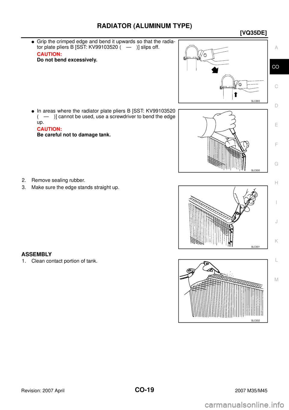
�Grip the crimped edge and bend it upwards so that the radia-
tor plate pliers B [SST: KV99103520 ( — )] slips off.
CAUTION:
Do not bend excessively.
�In areas where the radiator plate pliers B [SST: KV99103520
( — )] cannot be used, use a screwdriver to bend the edge
up.
CAUTION:
Be careful not to damage tank.
2. Remove sealing rubber.
3. Make sure the edge stands straight up.
ASSEMBLY
1. Clean contact portion of tank.
SLC893
SLC930
SLC931
SLC932
Page 1381 of 4647
CO-20
[VQ35DE]
RADIATOR (ALUMINUM TYPE)
Revision: 2007 April2007 M35/M45
2. Install new sealing rubber while pushing it with fingers.
CAUTION:
Be careful not to twist sealing rubber.
3. Caulk tank in numerical order as shown in the figure with the
radiator plate pliers A (SST).
�Use pliers in the locations where the radiator plate pliers A
[SST: KV99103510 ( — )] cannot be used.
SLC917A
SLC904-A
PBIC2076E
SLC897
Page 1382 of 4647
RADIATOR (ALUMINUM TYPE)
CO-21
[VQ35DE]
C
D
E
F
G
H
I
J
K
L
MA
CO
Revision: 2007 April2007 M35/M45
4. Make sure that the rim is completely crimped down.
5. Make sure that there is no leakage. Refer to CO-21, "
INSPECTION" .
INSPECTION
1. Apply pressure with the radiator cap tester adapter (commercial
service tool) (A) and the radiator cap tester (commercial service
tool).
WARNING:
To prevent the risk of hose coming undone while under
pressure, securely fasten it down with hose clamp.
CAUTION:
Attach hose to A/T fluid cooler to seal its inlet and outlet.
2. Check for leakage by soaking radiator in water container with
the testing pressure applied.Standard height “H” : 8.0 - 8.4 mm (0.315 - 0.331 in)
SLC554A
Testing pressure
: 157 kPa (1.6 kg/cm
2 , 23 psi)
PBIC5327E
SLC934

![INFINITI M35 2007 Factory Service Manual CO-18
[VQ35DE]
RADIATOR (ALUMINUM TYPE)
Revision: 2007 April2007 M35/M45
RADIATOR (ALUMINUM TYPE)PFP:21460
ComponentsNBS004QW
Disassembly and AssemblyNBS004QX
PREPARATION
1. Attach spacer to tip of th](/manual-img/42/57024/w960_57024-1378.png "INFINITI M35 2007 Factory Service Manual CO-18
[VQ35DE]
RADIATOR (ALUMINUM TYPE)
Revision: 2007 April2007 M35/M45
RADIATOR (ALUMINUM TYPE)PFP:21460
ComponentsNBS004QW
Disassembly and AssemblyNBS004QX
PREPARATION
1. Attach spacer to tip of th")
![INFINITI M35 2007 Factory Service Manual CO-20
[VQ35DE]
RADIATOR (ALUMINUM TYPE)
Revision: 2007 April2007 M35/M45
2. Install new sealing rubber while pushing it with fingers.
CAUTION:
Be careful not to twist sealing rubber.
3. Caulk tank in](/manual-img/42/57024/w960_57024-1380.png "INFINITI M35 2007 Factory Service Manual CO-20
[VQ35DE]
RADIATOR (ALUMINUM TYPE)
Revision: 2007 April2007 M35/M45
2. Install new sealing rubber while pushing it with fingers.
CAUTION:
Be careful not to twist sealing rubber.
3. Caulk tank in")
![INFINITI M35 2007 Factory Service Manual RADIATOR (ALUMINUM TYPE)
CO-21
[VQ35DE]
C
D
E
F
G
H
I
J
K
L
MA
CO
Revision: 2007 April2007 M35/M45
4. Make sure that the rim is completely crimped down.
5. Make sure that there is no leakage. Refer to](/manual-img/42/57024/w960_57024-1381.png "INFINITI M35 2007 Factory Service Manual RADIATOR (ALUMINUM TYPE)
CO-21
[VQ35DE]
C
D
E
F
G
H
I
J
K
L
MA
CO
Revision: 2007 April2007 M35/M45
4. Make sure that the rim is completely crimped down.
5. Make sure that there is no leakage. Refer to")