Page 1406 of 4647
![INFINITI M35 2007 Factory Service Manual RADIATOR
CO-45
[VK45DE]
C
D
E
F
G
H
I
J
K
L
MA
CO
Revision: 2007 April2007 M35/M45
INSPECTION AFTER INSTALLATION
�Check for leaks of engine coolant using radiator cap tester adapter (commercial servic](/manual-img/42/57024/w960_57024-1405.png "INFINITI M35 2007 Factory Service Manual RADIATOR
CO-45
[VK45DE]
C
D
E
F
G
H
I
J
K
L
MA
CO
Revision: 2007 April2007 M35/M45
INSPECTION AFTER INSTALLATION
�Check for leaks of engine coolant using radiator cap tester adapter (commercial servic")
RADIATOR
CO-45
[VK45DE]
C
D
E
F
G
H
I
J
K
L
MA
CO
Revision: 2007 April2007 M35/M45
INSPECTION AFTER INSTALLATION
�Check for leaks of engine coolant using radiator cap tester adapter (commercial service tool) and radiator
cap tester (commercial service tool). Refer to CO-40, "
LEAK CHECK" .
�Start and warm up engine. Visually Check if there is no leaks of engine coolant and A/T fluid.
Checking Radiator CapNBS004RI
�Check valve seat of radiator cap.
–Check if valve seat is swollen to the extent that the edge of the
plunger cannot be seen when watching it vertically from the top.
–Check if valve seat has no soil and damage.
�Pull negative-pressure valve to open it, and make sure that it
close completely when released.
–Make sure that there is no dirt or damage on the valve seat of
radiator cap negative-pressure valve.
–Make sure that there are no unusualness in the opening and
closing conditions of negative-pressure valve.
�Check radiator cap relief pressure.
–When connecting radiator cap to the radiator cap tester adapter
(commercial service tool) (B) and the radiator cap tester (com-
mercial service tool) (A), apply engine coolant to the cap seal
surface.
�Replace radiator cap if there is an unusualness.
CAUTION:
When installing a radiator cap, thoroughly wipe out the radiator filler neck to remove any waxy residue
or foreign material.
Checking RadiatorNBS004RJ
Check radiator for mud or clogging. If necessary, clean radiator as follows:
�Be careful not to bend or damage the radiator fins.
�When radiator is cleaned without removal, remove all surrounding parts such as cooling fan, radiator
shroud and horns. Then tape the harness and electrical connectors to prevent water from entering.
1. Apply water by hose to the back side of the radiator core vertically downward.
2. Apply water again to all radiator core surface once per minute.
3. Stop washing if any stains no longer flow out from radiator.
4. Blow air into the back side of radiator core vertically downward.
PBIC2816E
SMA967B
Standard : 78 - 98 kPa (0.8 - 1.0 kg/cm2 , 11 - 14 psi)
Limit : 59 kPa (0.6 kg/cm
2 , 9 psi)
PBIC5122J
Page 1407 of 4647
CO-46
[VK45DE]
RADIATOR
Revision: 2007 April2007 M35/M45
�Use compressed air lower than 490 kPa (5 kg/cm2 , 71 psi) and keep distance more than 30 cm (11.81
in).
5. Blow air again into all the radiator core surfaces once per minute until no water sprays out.
Page 1408 of 4647
RADIATOR (ALUMINUM TYPE)
CO-47
[VK45DE]
C
D
E
F
G
H
I
J
K
L
MA
CO
Revision: 2007 April2007 M35/M45
RADIATOR (ALUMINUM TYPE)PFP:21460
ComponentsNBS004RK
Disassembly and AssemblyNBS004RL
PREPARATION
1. Attach spacer to tip of radiator plate pliers A (SST).
Spacer specification: 18 mm (0.71 in) wide × 8.5 mm (0.335 in)
long × 1.5 mm (0.059 in) thick.
2. Make sure that when radiator plate pliers A [SST: KV99103510 ( — )] are closed dimension H′′ is
approx. 7.6 mm (0.299 in).
3. Adjust dimension H′′ with spacer, if necessary.
DISASSEMBLY
1. Remove upper and lower tanks with radiator plate pliers B
(SST).
CAUTION:
Do not disassemble lower tank and A/T fluid cooler.
NOTE:
Regard lower tank and A/T fluid cooler as an assembly.
1. Upper tank 2. Sealing rubber 3. Core
4. Lower tank (with A/T fluid cooler)
PBIC3397E
SLC655CB
SLC903-A
Page 1409 of 4647
CO-48
[VK45DE]
RADIATOR (ALUMINUM TYPE)
Revision: 2007 April2007 M35/M45
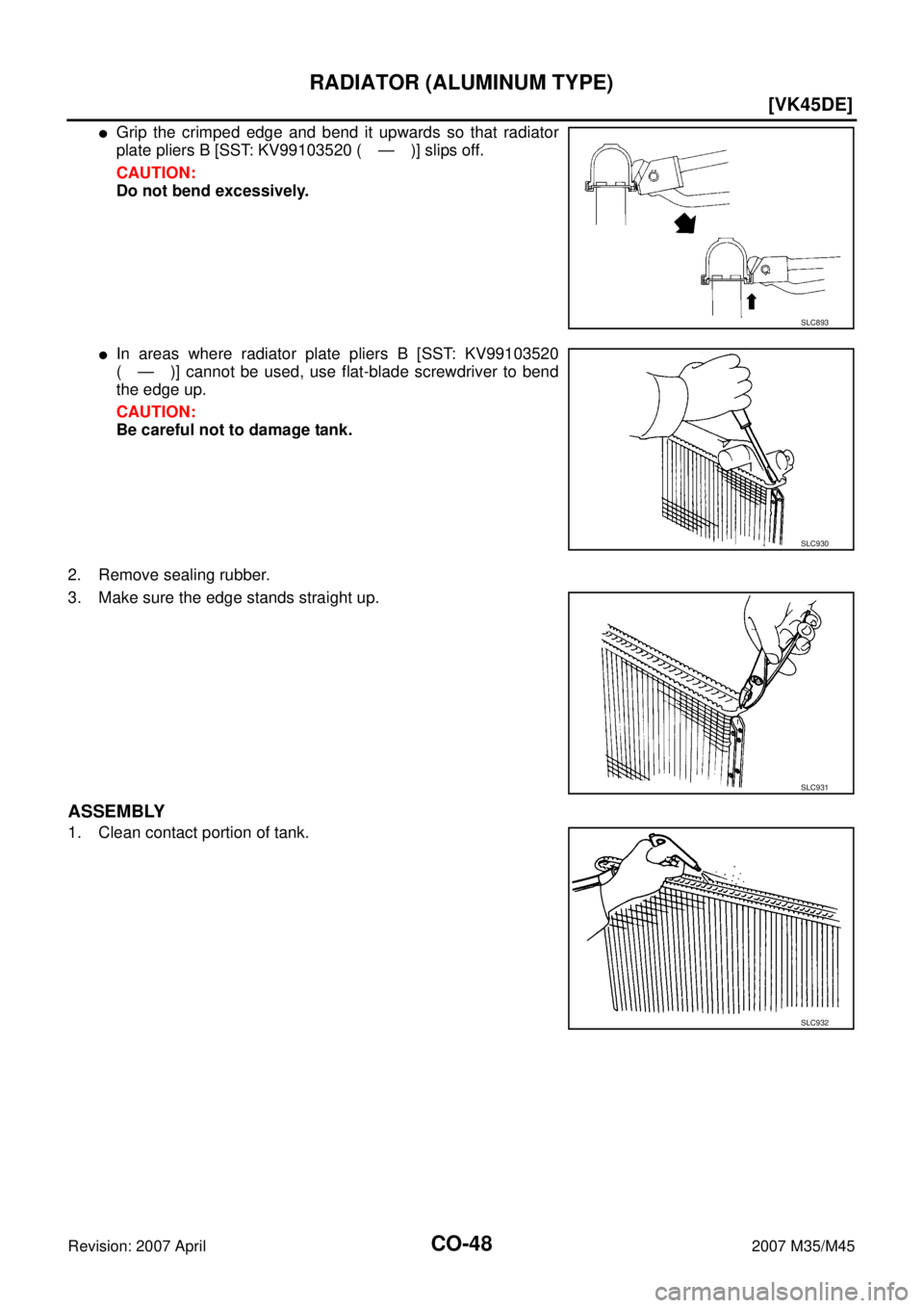
�Grip the crimped edge and bend it upwards so that radiator
plate pliers B [SST: KV99103520 ( — )] slips off.
CAUTION:
Do not bend excessively.
�In areas where radiator plate pliers B [SST: KV99103520
( — )] cannot be used, use flat-blade screwdriver to bend
the edge up.
CAUTION:
Be careful not to damage tank.
2. Remove sealing rubber.
3. Make sure the edge stands straight up.
ASSEMBLY
1. Clean contact portion of tank.
SLC893
SLC930
SLC931
SLC932
Page 1410 of 4647
RADIATOR (ALUMINUM TYPE)
CO-49
[VK45DE]
C
D
E
F
G
H
I
J
K
L
MA
CO
Revision: 2007 April2007 M35/M45
2. Install new sealing rubber while pushing it with fingers.
CAUTION:
Be careful not to twist sealing rubber.
3. Caulk tank in numerical order as shown in the figure with radia-
tor plate pliers A (SST).
�Use pliers in the locations where radiator plate pliers A [SST:
KV99103510 ( — )] cannot be used.
SLC917A
SLC904-A
PBIC2076E
SLC897
Page 1411 of 4647
![INFINITI M35 2007 Factory Service Manual CO-50
[VK45DE]
RADIATOR (ALUMINUM TYPE)
Revision: 2007 April2007 M35/M45
4. Make sure that the rim is completely crimped down.
5. Make sure that there is no leakage. Refer to CO-50, "
INSPECTION" .
IN](/manual-img/42/57024/w960_57024-1410.png "INFINITI M35 2007 Factory Service Manual CO-50
[VK45DE]
RADIATOR (ALUMINUM TYPE)
Revision: 2007 April2007 M35/M45
4. Make sure that the rim is completely crimped down.
5. Make sure that there is no leakage. Refer to CO-50, \"
INSPECTION\" .
IN")
CO-50
[VK45DE]
RADIATOR (ALUMINUM TYPE)
Revision: 2007 April2007 M35/M45
4. Make sure that the rim is completely crimped down.
5. Make sure that there is no leakage. Refer to CO-50, "
INSPECTION" .
INSPECTION
1. Apply pressure with radiator cap tester adapter (commercial ser-
vice tool) and radiator cap tester (commercial service tool).
�provide used radiator and connect it to tested radiator using
radiator hoses as shown in the figure.
NOTE:
The used radiator should be tested beforehand to confirm it
has no leakage. If used one is not available, it is possible to
use new service part as a radiator testing tool.
WARNING:
To prevent the risk of hose coming undone while under pressure, securely fasten it down with
hose clamp.
CAUTION:
Attach hose to A/T fluid cooler to seal its inlet and outlet.
2. Check for leakage by soaking radiator in water container with
the testing pressure applied.Standard height “H” : 8.0 - 8.4 mm (0.315 - 0.331 in)
SLC554A
Testing pressure
: 157 kPa (1.6 kg/cm
2 , 23 psi)PBIC5158E
PBIC1699E
Page 1412 of 4647
![INFINITI M35 2007 Factory Service Manual COOLING FAN
CO-51
[VK45DE]
C
D
E
F
G
H
I
J
K
L
MA
CO
Revision: 2007 April2007 M35/M45
COOLING FANPFP:21140
ComponentsNBS004RM
Removal and InstallationNBS004RN
REMOVAL
1. Remove engine room cover (RH a](/manual-img/42/57024/w960_57024-1411.png "INFINITI M35 2007 Factory Service Manual COOLING FAN
CO-51
[VK45DE]
C
D
E
F
G
H
I
J
K
L
MA
CO
Revision: 2007 April2007 M35/M45
COOLING FANPFP:21140
ComponentsNBS004RM
Removal and InstallationNBS004RN
REMOVAL
1. Remove engine room cover (RH a")
COOLING FAN
CO-51
[VK45DE]
C
D
E
F
G
H
I
J
K
L
MA
CO
Revision: 2007 April2007 M35/M45
COOLING FANPFP:21140
ComponentsNBS004RM
Removal and InstallationNBS004RN
REMOVAL
1. Remove engine room cover (RH and LH). Refer to EM-173, "ENGINE ROOM COVER" .
2. Remove air duct (inlet) and air cleaner case assembly. Refer to EM-177, "
AIR CLEANER AND AIR
DUCT" .
3. Drain engine coolant from radiator. Refer to CO-40, "
ENGINE COOLANT" .
4. Disconnect harness connector from cooling fan control module, and move harness to aside.
5. Remove radiator hose (upper). Refer to CO-43, "
RADIATOR" .
6. Remove cooling fan assembly.
CAUTION:
Be careful not to damage or scratch on radiator core.
INSTALLATION
Note the following, and Install in the reverse order of removal.
CAUTION:
Only use genuine parts for radiator shroud and cooling fan mounting bolt and observe the specified
torque (to prevent radiator from being damaged).
INSPECTION AFTER INSTALLATION
Make sure that fan motors operate normally.
1. Sub-harness 2. Cooling fan control module 3. Sub-harness
4. Fan motor (LH) 5. Fan motor (RH) 6. Fan shroud
7. Cooling fan (RH) 8. Cooling fan (LH)
A. Apply on fan motor shaft.
: Apply Genuine High Strength Lock-
ing Sealant or equivalent.
KBIA3567J
Page 1414 of 4647
![INFINITI M35 2007 Factory Service Manual WATER PUMP
CO-53
[VK45DE]
C
D
E
F
G
H
I
J
K
L
MA
CO
Revision: 2007 April2007 M35/M45
WAT E R P U MPPFP:21020
ComponentsNBS004RP
�Refer to GI-11, "Components" for symbols in the figure.
Removal and I](/manual-img/42/57024/w960_57024-1413.png "INFINITI M35 2007 Factory Service Manual WATER PUMP
CO-53
[VK45DE]
C
D
E
F
G
H
I
J
K
L
MA
CO
Revision: 2007 April2007 M35/M45
WAT E R P U MPPFP:21020
ComponentsNBS004RP
�Refer to GI-11, \"Components\" for symbols in the figure.
Removal and I")
WATER PUMP
CO-53
[VK45DE]
C
D
E
F
G
H
I
J
K
L
MA
CO
Revision: 2007 April2007 M35/M45
WAT E R P U MPPFP:21020
ComponentsNBS004RP
�Refer to GI-11, "Components" for symbols in the figure.
Removal and InstallationNBS004RQ
CAUTION:
�When removing water pump, be careful not to get engine coolant on drive belts.
�Water pump can not be disassembled and should be replaced as a unit.
�After installing water pump, connect hose and clamp securely, then check for leaks using radiator
cap tester (commercial service tool) and radiator cap tester adapter (commercial service tool).
REMOVAL
1. Remove following parts:
�Front engine undercover (power tool)
�Engine cover: Refer to EM-179, "INTAKE MANIFOLD" .
�Engine room cover (RH and LH): Refer to EM-173, "ENGINE ROOM COVER" .
�Air duct (inlet): Refer to EM-177, "AIR CLEANER AND AIR DUCT" .
�Alternator, water pump and A/C compressor belt: Refer to EM-174, "DRIVE BELTS" .
2. Drain engine coolant from drain plugs on radiator and both side of cylinder block. Refer to CO-40, "
Chang-
ing Engine Coolant" and EM-253, "DISASSEMBLY" .
CAUTION:
�Perform this step when engine is cold.
�Do not spill engine coolant on drive belts.
3. Remove water pump pulley.
4. Remove water pump.
�Engine coolant will leak from cylinder block, so have a receptacle ready under vehicle.
CAUTION:
�Handle the water pump vane so that it does not contact any other parts.
�Do not disassemble water pump.
1. Water pump 2. Water pump pulley 3. Gasket
PBIC3396E

![INFINITI M35 2007 Factory Service Manual RADIATOR (ALUMINUM TYPE)
CO-47
[VK45DE]
C
D
E
F
G
H
I
J
K
L
MA
CO
Revision: 2007 April2007 M35/M45
RADIATOR (ALUMINUM TYPE)PFP:21460
ComponentsNBS004RK
Disassembly and AssemblyNBS004RL
PREPARATION
1.](/manual-img/42/57024/w960_57024-1407.png "INFINITI M35 2007 Factory Service Manual RADIATOR (ALUMINUM TYPE)
CO-47
[VK45DE]
C
D
E
F
G
H
I
J
K
L
MA
CO
Revision: 2007 April2007 M35/M45
RADIATOR (ALUMINUM TYPE)PFP:21460
ComponentsNBS004RK
Disassembly and AssemblyNBS004RL
PREPARATION
1.")
![INFINITI M35 2007 Factory Service Manual RADIATOR (ALUMINUM TYPE)
CO-49
[VK45DE]
C
D
E
F
G
H
I
J
K
L
MA
CO
Revision: 2007 April2007 M35/M45
2. Install new sealing rubber while pushing it with fingers.
CAUTION:
Be careful not to twist sealing](/manual-img/42/57024/w960_57024-1409.png "INFINITI M35 2007 Factory Service Manual RADIATOR (ALUMINUM TYPE)
CO-49
[VK45DE]
C
D
E
F
G
H
I
J
K
L
MA
CO
Revision: 2007 April2007 M35/M45
2. Install new sealing rubber while pushing it with fingers.
CAUTION:
Be careful not to twist sealing")