Page 1151 of 4647
BL-218
VEHICLE SECURITY (THEFT WARNING) SYSTEM
Revision: 2007 April2007 M35/M45
1. Fuse block (J/B) fuse layout 2. IPDM E/R fuse layout 3. Fuse and fusible link box
4. BCM M1, M2 (View with instrument
lower panel RH removed)5. IPDM E/R E8, E9
(Engine room)6. Security indicator M69
(Multifunction switch)
7. Key slot M14 8. Hood switch E44
(Hood lock assembly)9. Intelligent key unit M32 (View with
dash side finisher LH removed)
10. Remote keyless entry receiver M89
(View with instrument lower panel RH
removed)11. Power window main switch
D10, D11 (Driver side)12. Power window sub switch
D46 (Passenger side)
13. Front door lock assembly LH D14
(Key cylinder switch)14. Front door switch B11
(Driver side)15. Rear door switch LH B53
16. trunk lid lock assembly T106
(Trunk room lamp switch)17. Trunk lid key cylinder switch T104 18. Horn (low) E56, E57 (View with front
fender protector LH removed)
19. Horn (high) E64, E65 (View with front
grille removed)
PIIB5893E
Page 1166 of 4647

VEHICLE SECURITY (THEFT WARNING) SYSTEM
BL-233
C
D
E
F
G
H
J
K
L
MA
B
BL
Revision: 2007 April2007 M35/M45
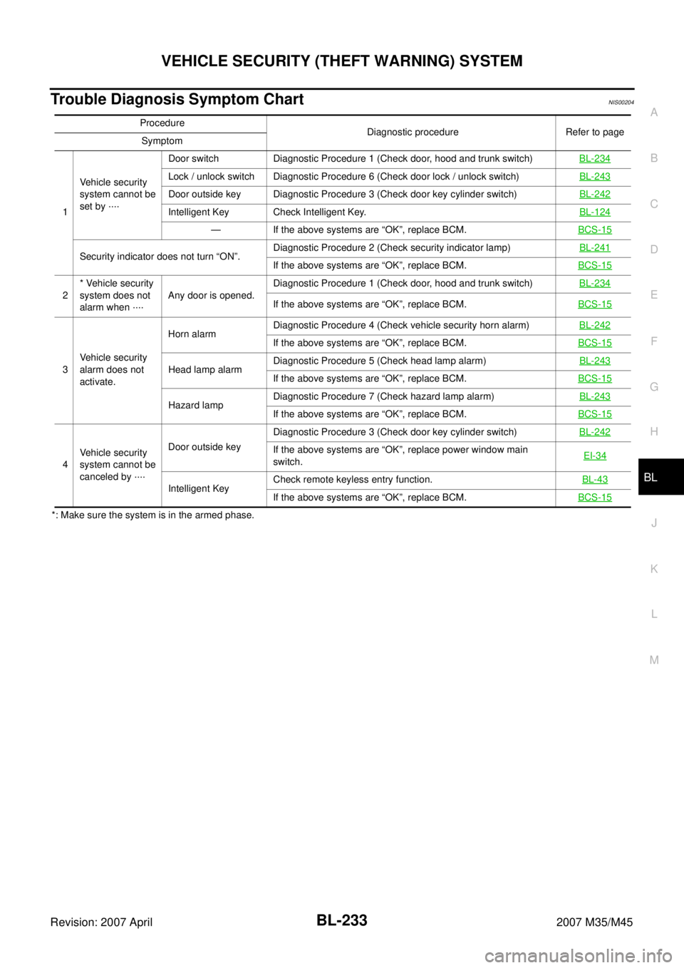
Trouble Diagnosis Symptom ChartNIS00204
*: Make sure the system is in the armed phase.Procedure
Diagnostic procedure Refer to page
Symptom
1Vehicle security
system cannot be
set by ····Door switch Diagnostic Procedure 1 (Check door, hood and trunk switch) BL-234
Lock / unlock switch Diagnostic Procedure 6 (Check door lock / unlock switch)BL-243
Door outside key Diagnostic Procedure 3 (Check door key cylinder switch)BL-242
Intelligent Key Check Intelligent Key.BL-124
— If the above systems are “OK”, replace BCM.BCS-15
Security indicator does not turn “ON”.Diagnostic Procedure 2 (Check security indicator lamp)BL-241If the above systems are “OK”, replace BCM.BCS-15
2* Vehicle security
system does not
alarm when ····Any door is opened.Diagnostic Procedure 1 (Check door, hood and trunk switch)BL-234If the above systems are “OK”, replace BCM.BCS-15
3Vehicle security
alarm does not
activate.Horn alarmDiagnostic Procedure 4 (Check vehicle security horn alarm)BL-242
If the above systems are “OK”, replace BCM.BCS-15
Head lamp alarmDiagnostic Procedure 5 (Check head lamp alarm)BL-243If the above systems are “OK”, replace BCM.BCS-15
Hazard lampDiagnostic Procedure 7 (Check hazard lamp alarm)BL-243If the above systems are “OK”, replace BCM.BCS-15
4Vehicle security
system cannot be
canceled by ····Door outside keyDiagnostic Procedure 3 (Check door key cylinder switch)BL-242
If the above systems are “OK”, replace power window main
switch.EI-34
Intelligent KeyCheck remote keyless entry function.BL-43If the above systems are “OK”, replace BCM.BCS-15
Page 3746 of 4647

ILLUMINATION
LT-295
C
D
E
F
G
H
I
J
L
MA
B
LT
Revision: 2007 April2007 M35/M45
�to door mirror remote control switch (illumination) terminal 15
�to AFS switch (illumination) terminal 6 (with AFS)
�to rear sunshade front switch (illumination) terminal 6 (with rear control switch)
�to A/T illumination terminal 2
�to snow mode switch (illumination) terminal 6 (ADW models)
�to rear control cancel switch (illumination) terminal 5 (with rear control switch)
�to clock terminal 4
�to multifunction switch terminal 4
�to audio unit terminal 8
�to DVD player terminal 17 (With DVD player)
�to climate controlled seat switch driver side (illumination) terminal 8 (with climate controlled seat) and
�to climate controlled seat switch passenger side (illumination) terminal 8 (with climate controlled seat)
�through illumination control switch terminal 2
�to illumination control switch terminal 3
�through grounds M16 and M70,
�to cigarette lighter socket (illumination) terminal 1
�to map lamp (illumination) terminal 4
�to power window main switch illumination terminal 2 and
�to glove box lamp terminal 2
�through grounds M16 and M70,
�to ashtray illumination (rear RH) terminal 2
�through grounds B402, B405,
�to ashtray illumination (rear LH) terminal 2
�to automatic return cancel switch (illumination) terminal 2 (With rear control switch)
�to rear power seat switch LH (illumination) terminal 3 (With rear control switch)
�to rear heated seat switch LH (illumination) terminal 8 (With rear control switch)
�through grounds B5, B40 and B131,
�through rear sunshade cancel relay terminal 7(With rear control switch)
�to rear sunshade rear switch (illumination) terminal 7 (With rear control switch)
�through grounds B5, B40, B131 and B559.
�to rear control switch terminal 4
�to rear power seat switch RH (illumination) terminal 3 (With rear control switch)
�to rear heated seat switch RH (illumination) terminal 8 (With rear control switch)
�through grounds B5, B40, B131 and B559.
With power and ground supplied, illumination lamps illuminate.
EXTERIOR LAMP BATTERY SAVER CONTROL
BCM activates the exterior lamp battery saver control function and turns off the exterior lamps to prevent bat-
tery from over discharge when the combination switch (lighting switch) is in 1ST or 2ND position and/or the
front fog lamp switch ON and the door lock operation is performed by keyless entry system.
CAN Communication System DescriptionNKS003TI
CAN (Controller Area Network) is a serial communication line for real time application. It is an on-vehicle mul-
tiplex communication line with high data communication speed and excellent error detection ability. Many elec-
tronic control units are equipped onto a vehicle, and each control unit shares information and links with other
control units during operation (not independent). In CAN communication, control units are connected with 2
communication lines (CAN H line, CAN L line) allowing a high rate of information transmission with less wiring.
Each control unit transmits/receives data but selectively reads required data only.
CAN Communication UnitNKS003TJ
Refer to LAN-50, "CAN System Specification Chart" .