Page 1434 of 4647
COMBINATION METERS
DI-15
C
D
E
F
G
H
I
J
L
MA
B
DI
Revision: 2007 April2007 M35/M45
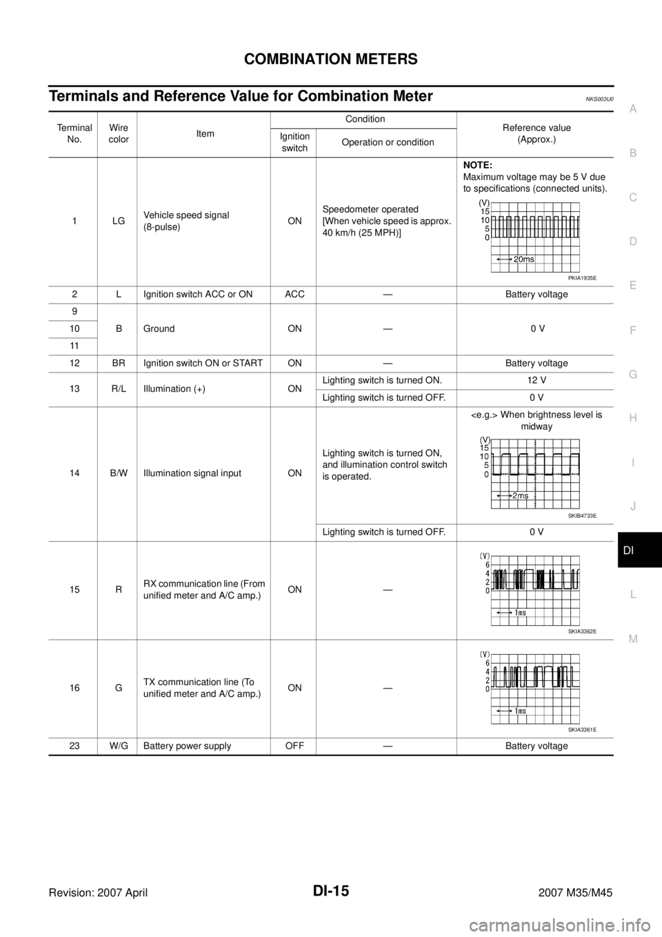
Terminals and Reference Value for Combination MeterNKS003U0
Terminal
No.Wire
colorItemCondition
Reference value
(Approx.) Ignition
switchOperation or condition
1LGVehicle speed signal
(8-pulse)ONSpeedometer operated
[When vehicle speed is approx.
40 km/h (25 MPH)]NOTE:
Maximum voltage may be 5 V due
to specifications (connected units).
2 L Ignition switch ACC or ON ACC — Battery voltage
9
B Ground ON — 0 V 10
11
12 BR Ignition switch ON or START ON — Battery voltage
13 R/L Illumination (+) ONLighting switch is turned ON. 12 V
Lighting switch is turned OFF. 0 V
14 B/W Illumination signal input ONLighting switch is turned ON,
and illumination control switch
is operated. When brightness level is
midway
Lighting switch is turned OFF. 0 V
15 RRX communication line (From
unified meter and A/C amp.)ON —
16 GTX communication line (To
unified meter and A/C amp.)ON —
23 W/G Battery power supply OFF — Battery voltage
PKIA1935E
SKIB4733E
SKIA3362E
SKIA3361E
Page 1435 of 4647
DI-16
COMBINATION METERS
Revision: 2007 April2007 M35/M45
Terminals and Reference Value for Unified Meter and A/C Amp.NKS003U1
Te r m i n a l
No.Wire
colorItemCondition
Reference value
(Approx.) Ignition
switchOperation or condition
7RTX communication line
(To combination meter)ON —
27 GRX communication line
(From combination meter)ON —
28 LGVehicle speed signal output
(8-pulse)ONSpeedometer operated
[When vehicle speed is
approx. 40 km/h (25 MPH)]NOTE:
Maximum voltage may be 5 V due to
specifications (connected units).
41 V Ignition switch ACC or ON ACC — Battery voltage
42 P/L Fuel level sensor signal — —
53 W/G Ignition switch ON or START ON — Battery voltage
54 W/G Battery power supply OFF — Battery voltage
55 B Ground ON — 0 V
56 L CAN–H — — —
58 B Fuel level sensor ground ON — 0 V
71 B Ground (power) ON — 0 V
72 P CAN–L — — —
SKIA3362E
SKIA3361E
PKIA1935E
SKIB8867E
Page 1438 of 4647
COMBINATION METERS
DI-19
C
D
E
F
G
H
I
J
L
MA
B
DI
Revision: 2007 April2007 M35/M45
Power Supply and Ground Circuit InspectionNKS003U6
Symptom : When any power supply circuit is malfunction, the following function is not operative.
�BAT : Meter face illumination, Dot matrix LCD, Ring illumination, Turn signal/hazard indicator lights
�ACC : Meter face illumination, Dot matrix LCD, Pointer illumination, Speedometer, Tachometer
�IGN : Meter face illumination, Dot matrix LCD, Pointer illumination, Speedometer, Tachometer, Engine
coolant temperature, Fuel gauge
1. CHECK FUSE
Check for blown fuses.
OK or NG
OK >> GO TO 2.
NG >> Be sure to eliminate cause of malfunction before installing new fuse. Refer to PG-3, "
POWER
SUPPLY ROUTING CIRCUIT" .
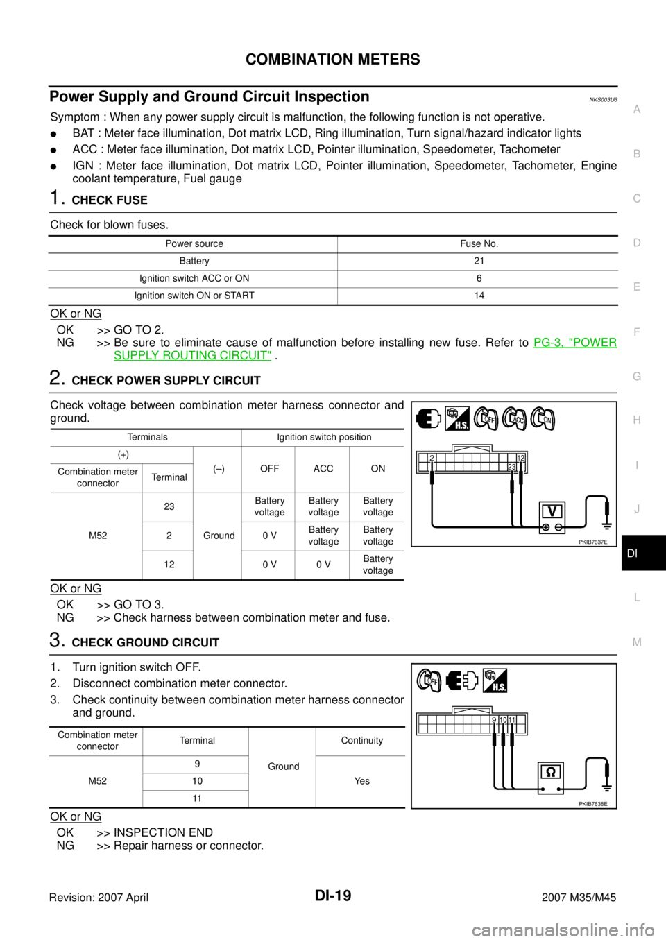
2. CHECK POWER SUPPLY CIRCUIT
Check voltage between combination meter harness connector and
ground.
OK or NG
OK >> GO TO 3.
NG >> Check harness between combination meter and fuse.
3. CHECK GROUND CIRCUIT
1. Turn ignition switch OFF.
2. Disconnect combination meter connector.
3. Check continuity between combination meter harness connector
and ground.
OK or NG
OK >> INSPECTION END
NG >> Repair harness or connector.
Power source Fuse No.
Battery 21
Ignition switch ACC or ON 6
Ignition switch ON or START 14
Terminals Ignition switch position
(+)
(–) OFF ACC ON
Combination meter
connectorTerminal
M5223
GroundBattery
voltageBattery
voltageBattery
voltage
20 VBattery
voltageBattery
voltage
12 0 V 0 VBattery
voltage
PKIB7637E
Combination meter
connectorTerminal
GroundContinuity
M529
Ye s 10
11
PKIB7638E
Page 1450 of 4647
UNIFIED METER AND A/C AMP
DI-31
C
D
E
F
G
H
I
J
L
MA
B
DI
Revision: 2007 April2007 M35/M45
CONSULT-II Function (METER A/C AMP)NKS003UI
CONSULT-II can display each diagnostic item using the diagnostic test modes shown following.
CONSULT-II BASIC OPERATION
Refer to GI-38, "CONSULT-II Start Procedure" .
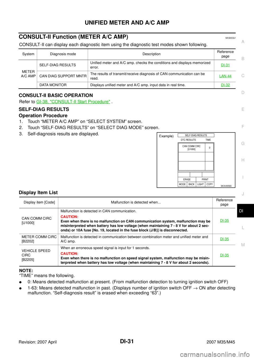
SELF-DIAG RESULTS
Operation Procedure
1. Touch “METER A/C AMP” on “SELECT SYSTEM” screen.
2. Touch “SELF-DIAG RESULTS” on “SELECT DIAG MODE” screen.
3. Self-diagnosis results are displayed.
Display Item List
NOTE:
“TIME” means the following.
�0: Means detected malfunction at present. (From malfunction detection to turning ignition switch OFF)
�1-63: Means detected malfunction in past. (Displays number of ignition switch OFF → ON after detecting
malfunction. “Self-diagnosis result” is erased when exceeding “63”.)
System Diagnosis mode DescriptionReference
page
METER
A/C AMPSELF-DIAG RESULTSUnified meter and A/C amp. checks the conditions and displays memorized
error.DI-31
CAN DIAG SUPPORT MNTRThe results of transmit/receive diagnosis of CAN communication can be
read.LAN-44
DATA MONITOR Displays unified meter and A/C amp. input data in real time.DI-32
SKIA4956E
Display item [Code] Malfunction is detected when...Reference
page
CAN COMM CIRC
[U1000]Malfunction is detected in CAN communication.
CAUTION:
Even when there is no malfunction on CAN communication system, malfunction may be
misinterpreted when battery has low voltage (when maintaining 7 - 8 V for about 2 sec-
onds) or 10A fuse [No. 19, located in the fuse block (J/B)] is disconnected.DI-35
METER COMM CIRC
[B2202]Malfunction is detected in communication between combination meter and unified meter and
A/C amp.DI-35
VEHICLE SPEED
CIRC
[B2205]When an erroneous speed signal is input for 1 seconds.
CAUTION:
Even when there is no malfunction on speed signal system, malfunction may be misin-
terpreted when battery has low voltage (when maintaining 7 - 8 V for about 2 seconds). DI-35
Page 1453 of 4647
DI-34
UNIFIED METER AND A/C AMP
Revision: 2007 April2007 M35/M45
Power Supply and Ground Circuit InspectionNKS003UJ
1. CHECK FUSE
Check for blown fuses.
OK or NG
OK >> GO TO 2.
NG >> Be sure to eliminate cause of malfunction before installing new fuse. Refer to PG-3, "
POWER
SUPPLY ROUTING CIRCUIT" .
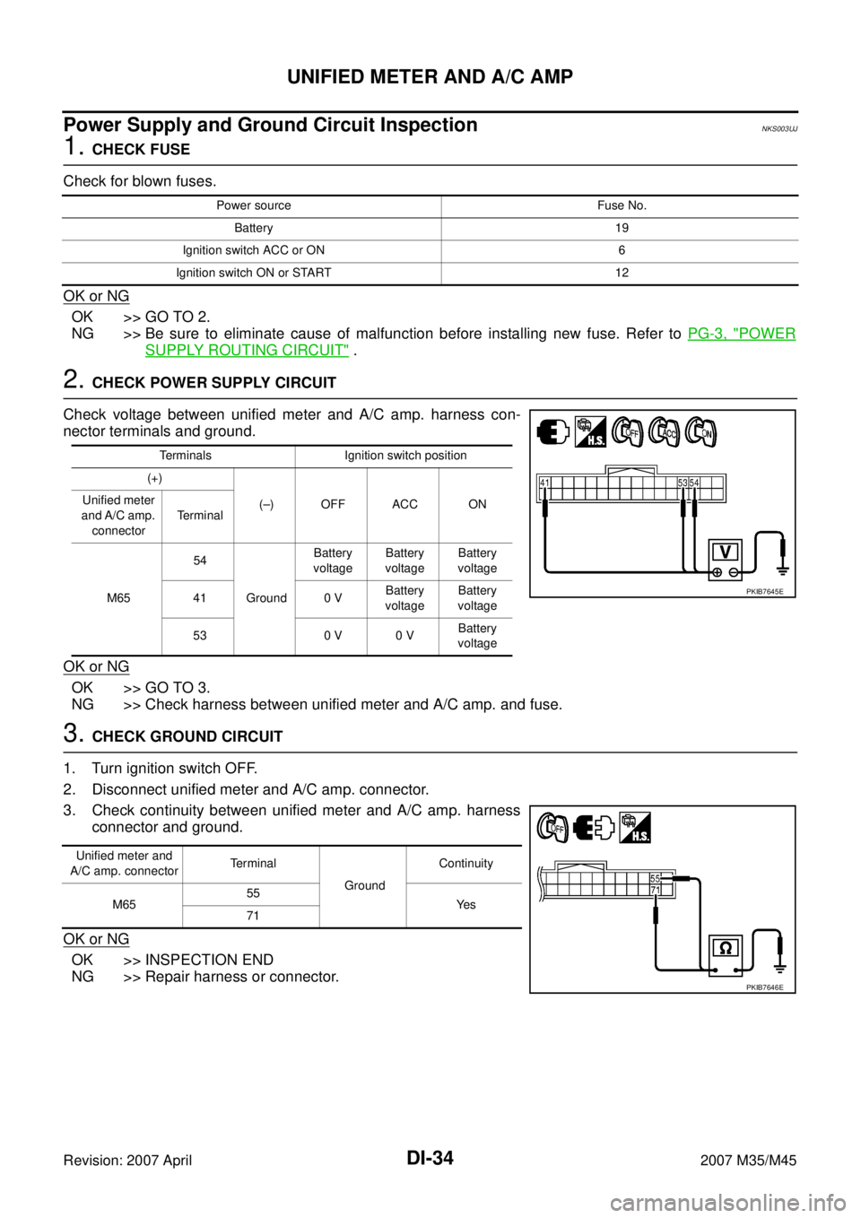
2. CHECK POWER SUPPLY CIRCUIT
Check voltage between unified meter and A/C amp. harness con-
nector terminals and ground.
OK or NG
OK >> GO TO 3.
NG >> Check harness between unified meter and A/C amp. and fuse.
3. CHECK GROUND CIRCUIT
1. Turn ignition switch OFF.
2. Disconnect unified meter and A/C amp. connector.
3. Check continuity between unified meter and A/C amp. harness
connector and ground.
OK or NG
OK >> INSPECTION END
NG >> Repair harness or connector.
Power source Fuse No.
Battery 19
Ignition switch ACC or ON 6
Ignition switch ON or START 12
Terminals Ignition switch position
(+)
(–) OFF ACC ON Unified meter
and A/C amp.
connectorTe r m i n a l
M6554
GroundBattery
voltageBattery
voltageBattery
voltage
41 0 VBattery
voltageBattery
voltage
53 0 V 0 VBattery
voltage
PKIB7645E
Unified meter and
A/C amp. connectorTe r m i n a l
GroundContinuity
M6555
Ye s
71
PKIB7646E
Page 1485 of 4647
DI-66
WARNING CHIME
Revision: 2007 April2007 M35/M45
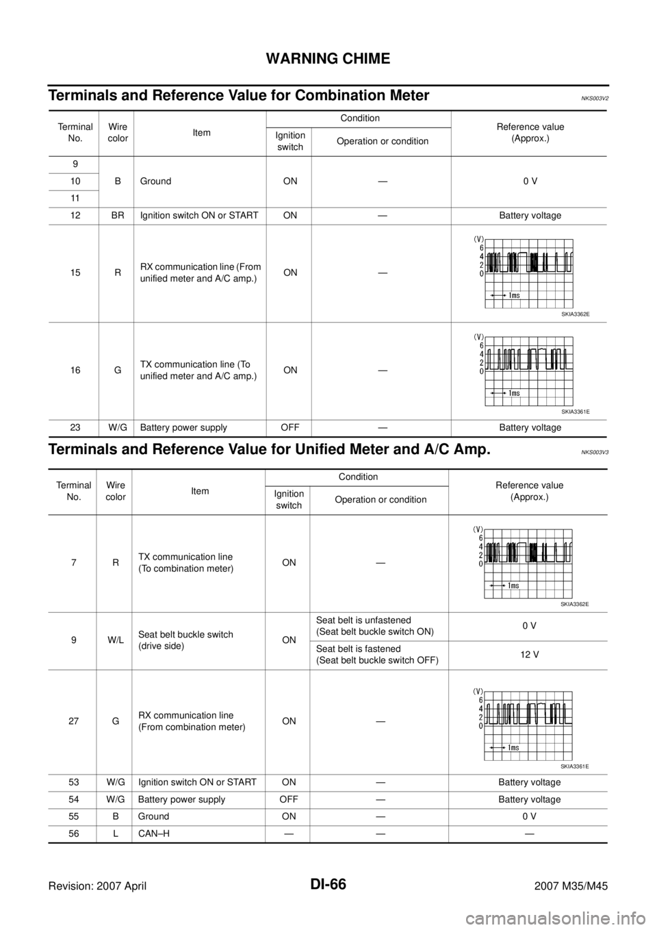
Terminals and Reference Value for Combination MeterNKS003V2
Terminals and Reference Value for Unified Meter and A/C Amp.NKS003V3
Terminal
No.Wire
colorItemCondition
Reference value
(Approx.) Ignition
switchOperation or condition
9
B Ground ON — 0 V 10
11
12 BR Ignition switch ON or START ON — Battery voltage
15 RRX communication line (From
unified meter and A/C amp.)ON —
16 GTX communication line (To
unified meter and A/C amp.)ON —
23 W/G Battery power supply OFF — Battery voltage
SKIA3362E
SKIA3361E
Te r m i n a l
No.Wire
colorItemCondition
Reference value
(Approx.) Ignition
switchOperation or condition
7RTX communication line
(To combination meter)ON —
9W/LSeat belt buckle switch
(drive side)ONSeat belt is unfastened
(Seat belt buckle switch ON)0 V
Seat belt is fastened
(Seat belt buckle switch OFF)12 V
27 GRX communication line
(From combination meter)ON —
53 W/G Ignition switch ON or START ON — Battery voltage
54 W/G Battery power supply OFF — Battery voltage
55 B Ground ON — 0 V
56 L CAN–H — — —
SKIA3362E
SKIA3361E
Page 1486 of 4647
WARNING CHIME
DI-67
C
D
E
F
G
H
I
J
L
MA
B
DI
Revision: 2007 April2007 M35/M45
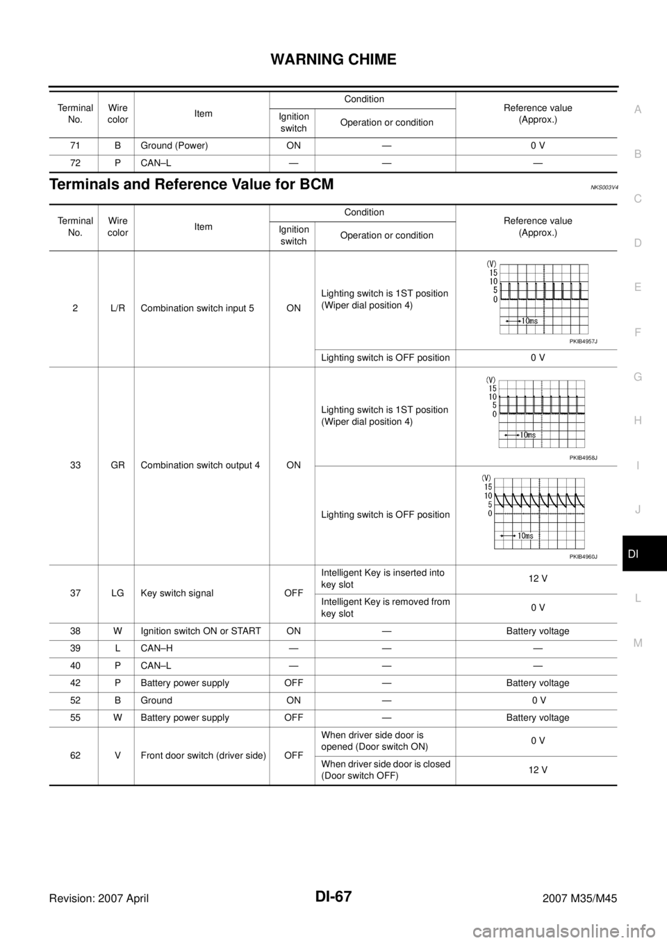
Terminals and Reference Value for BCMNKS003V4
71 B Ground (Power) ON — 0 V
72 P CAN–L — — — Terminal
No.Wire
colorItemCondition
Reference value
(Approx.) Ignition
switchOperation or condition
Terminal
No.Wire
colorItemCondition
Reference value
(Approx.) Ignition
switchOperation or condition
2 L/R Combination switch input 5 ONLighting switch is 1ST position
(Wiper dial position 4)
Lighting switch is OFF position 0 V
33 GR Combination switch output 4 ONLighting switch is 1ST position
(Wiper dial position 4)
Lighting switch is OFF position
37 LG Key switch signal OFFIntelligent Key is inserted into
key slot12 V
Intelligent Key is removed from
key slot0 V
38 W Ignition switch ON or START ON — Battery voltage
39 L CAN–H — — —
40 P CAN–L — — —
42 P Battery power supply OFF — Battery voltage
52 B Ground ON — 0 V
55 W Battery power supply OFF — Battery voltage
62 V Front door switch (driver side) OFFWhen driver side door is
opened (Door switch ON)0 V
When driver side door is closed
(Door switch OFF)12 V
PKIB4957J
PKIB4958J
PKIB4960J
Page 1489 of 4647
DI-70
WARNING CHIME
Revision: 2007 April2007 M35/M45
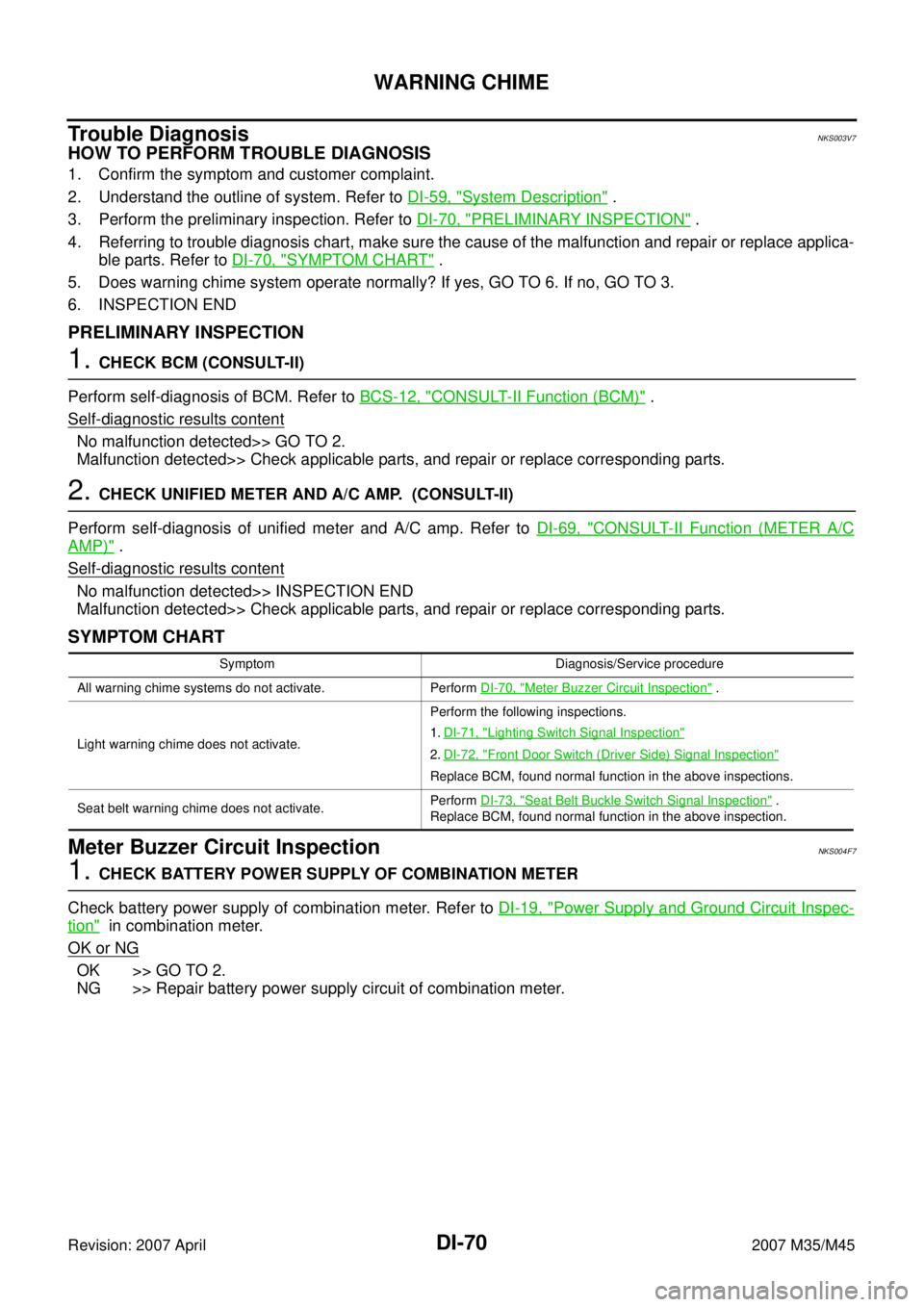
Trouble DiagnosisNKS003V7
HOW TO PERFORM TROUBLE DIAGNOSIS
1. Confirm the symptom and customer complaint.
2. Understand the outline of system. Refer to DI-59, "
System Description" .
3. Perform the preliminary inspection. Refer to DI-70, "
PRELIMINARY INSPECTION" .
4. Referring to trouble diagnosis chart, make sure the cause of the malfunction and repair or replace applica-
ble parts. Refer to DI-70, "
SYMPTOM CHART" .
5. Does warning chime system operate normally? If yes, GO TO 6. If no, GO TO 3.
6. INSPECTION END
PRELIMINARY INSPECTION
1. CHECK BCM (CONSULT-II)
Perform self-diagnosis of BCM. Refer to BCS-12, "
CONSULT-II Function (BCM)" .
Self
-diagnostic results content
No malfunction detected>> GO TO 2.
Malfunction detected>> Check applicable parts, and repair or replace corresponding parts.
2. CHECK UNIFIED METER AND A/C AMP. (CONSULT-II)
Perform self-diagnosis of unified meter and A/C amp. Refer to DI-69, "
CONSULT-II Function (METER A/C
AMP)" .
Self
-diagnostic results content
No malfunction detected>> INSPECTION END
Malfunction detected>> Check applicable parts, and repair or replace corresponding parts.
SYMPTOM CHART
Meter Buzzer Circuit InspectionNKS004F7
1. CHECK BATTERY POWER SUPPLY OF COMBINATION METER
Check battery power supply of combination meter. Refer to DI-19, "
Power Supply and Ground Circuit Inspec-
tion" in combination meter.
OK or NG
OK >> GO TO 2.
NG >> Repair battery power supply circuit of combination meter.
Symptom Diagnosis/Service procedure
All warning chime systems do not activate. Perform DI-70, "
Meter Buzzer Circuit Inspection" .
Light warning chime does not activate.Perform the following inspections.
1.DI-71, "
Lighting Switch Signal Inspection"
2.DI-72, "Front Door Switch (Driver Side) Signal Inspection"
Replace BCM, found normal function in the above inspections.
Seat belt warning chime does not activate.Perform DI-73, "
Seat Belt Buckle Switch Signal Inspection" .
Replace BCM, found normal function in the above inspection.