Page 991 of 4647

BL-58
INTELLIGENT KEY SYSTEM
Revision: 2007 April2007 M35/M45
List of Operation Related Parts
Parts marked with × are the parts related to operation.
Warning function
Intelligent Key
Key slot
Ignition switch
Door switch
Door request switch
Inside key antenna
Outside key antenna
Intelligent Key warning buzzer
Combination meter warning buzzer
Intelligent Key unit
CAN communication system
BCM
Combination meter display
Key slot illumination
Park position switch
“KEY” warning lamp
Intelligent Key system malfunction×× ×
OFF position warningFor internal×××××
For external×××××
P position warning××××××
ACC warning××××××
Take away warningDoor is open or close× × × ×××××××
Door is open× × × ×××××
Push-ignition switch
operation× × × ××× ××
Take away through win-
dow×××××××
Intelligent Key is
removed from key slot×× × ×× ××
Door lock operation warning×× ××××× ×××
Key warning×× × ××××××
Intelligent Key insert information×××× × ×××××
Engine start informationIgnition switch is ON
position××× × ×× × ×
Ignition switch is except
ON position××× × ×× ×
Steering lock information××××
Intelligent Key low battery warning×××××
Key ID warning××× × ×× ×
Page 1057 of 4647

BL-124
INTELLIGENT KEY SYSTEM
Revision: 2007 April2007 M35/M45
Intelligent Key Battery ReplacementNIS001Y6
DISASSEMBLY AND ASSEMBLY OF INTELLIGENT KEY
1. Release the lock knob at the back of the Intelligent Key and remove the mechanical key.
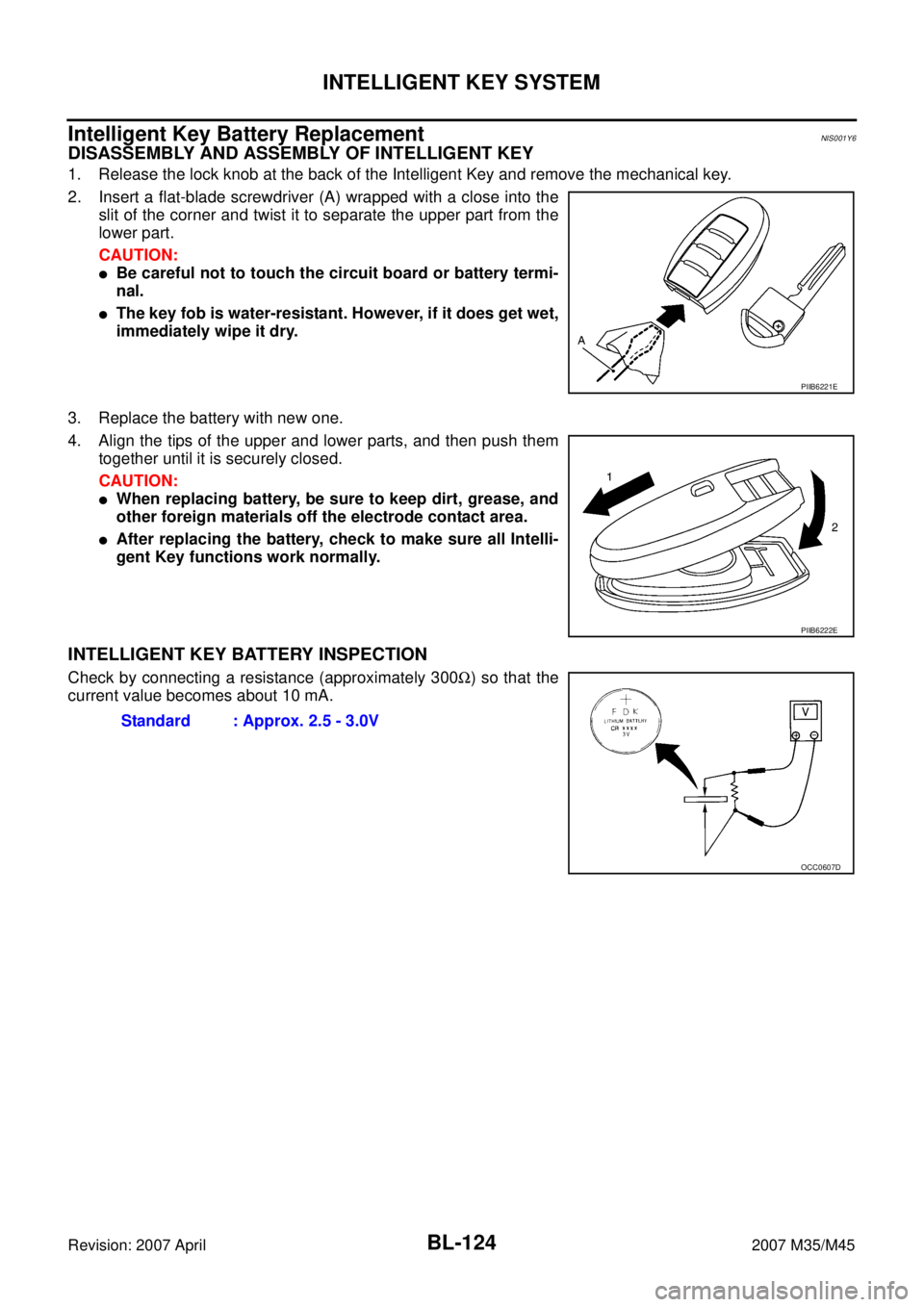
2. Insert a flat-blade screwdriver (A) wrapped with a close into the
slit of the corner and twist it to separate the upper part from the
lower part.
CAUTION:
�Be careful not to touch the circuit board or battery termi-
nal.
�The key fob is water-resistant. However, if it does get wet,
immediately wipe it dry.
3. Replace the battery with new one.
4. Align the tips of the upper and lower parts, and then push them
together until it is securely closed.
CAUTION:
�When replacing battery, be sure to keep dirt, grease, and
other foreign materials off the electrode contact area.
�After replacing the battery, check to make sure all Intelli-
gent Key functions work normally.
INTELLIGENT KEY BATTERY INSPECTION
Check by connecting a resistance (approximately 300Ω) so that the
current value becomes about 10 mA.
PIIB6221E
PIIB6222E
Standard : Approx. 2.5 - 3.0V
OCC0607D
Page 1058 of 4647
INTELLIGENT KEY SYSTEM/ENGINE START FUNCTION
BL-125
C
D
E
F
G
H
J
K
L
MA
B
BL
Revision: 2007 April2007 M35/M45
INTELLIGENT KEY SYSTEM/ENGINE START FUNCTIONPFP:285F1
Component Parts and Harness Connector LocationNIS001Y7
1. Fuse block (J/B) fuse layout 2. Fuse and fusible link box 3. BCM (View with instrument lower
panel RH removed) M1, M2
4. Intelligent key unit (View with dash
side finisher LH removed) M32, M335. PDU (View with combination meter
removed) M30, M316. IPDM E/R (Engine room) E4, E9
7. ECM (View with instrument lower
cover RH removed) M718. Push-button ignition switch M27 9. Stop lamp switch E124
PIIB5894E
Page 1134 of 4647
TRUNK LID
BL-201
C
D
E
F
G
H
J
K
L
MA
B
BL
Revision: 2007 April2007 M35/M45
TRUNK LIDPFP:H4300
Fitting AdjustmentNIS001ZH
1. Check the clearance and the evenness between the trunk lid and eack part by visual and tactile feeling.
(Fitting standard dimension in the table below should be satisfied.)
* Unit: mm (in)
2. In case out of specification, adjust them according to the procedures shown below.
�Loosen the bumper rubber.
1. Trunk lid assembly 2. Rear fender 3. Rear combination lamp
4. Rear bumper fascia 5. Bumper rubber 6. Trunk lid hinge
7. Trunk lid striker
Parts Standard Right/left clearance (MAX)
A – Aa 2.5 - 4.5 (01.0 - 0.18) 1.5 (0.06)
b -1.0 - 1.0 (-0.04 - 0.04) 1.5 (0.06)
B – Ba 2.5 - 5.5 (0.10 - 0.22) 2.0 (0.08)
b -1.5 - 1.5 (-0.06 - 0.06) 2.0 (0.08)
C – C a 2.4 - 6.6 (0.09 - 0.26) —
PIIB5817E
Page 1140 of 4647
TRUNK LID OPENER
BL-207
C
D
E
F
G
H
J
K
L
MA
B
BL
Revision: 2007 April2007 M35/M45
TRUNK LID OPENERPFP:84640
Component Parts and Harness Connector LocationNIS001ZN
1. Fuse block (J / B) fuse layout 2. Fuse and fusible link box 3. BCM M1, M2, M3 (View with instru-
ment lower panel RH removed)
4. Intelligent key unit M32 (View with
dash side finisher LH removed)5. Unified meter and A / C AMP M65 6. Trunk lid opener switch M25
7. Trunk lid lock assembly T106
(Trunk lid opener actuator)8. Trunk lid opener cancel switch M99
(Glove box inside)
PIIB5916E
Page 1150 of 4647
VEHICLE SECURITY (THEFT WARNING) SYSTEM
BL-217
C
D
E
F
G
H
J
K
L
MA
B
BL
Revision: 2007 April2007 M35/M45
VEHICLE SECURITY (THEFT WARNING) SYSTEMPFP:28491
Component Parts and Harness Connector LocationNIS001ZT
PIIB5863E
Page 1177 of 4647
BL-244
IVIS (INFINITI VEHICLE IMMOBILIZER SYSTEM-NATS)
Revision: 2007 April2007 M35/M45
IVIS (INFINITI VEHICLE IMMOBILIZER SYSTEM-NATS)PFP:28591
Component Parts and Harness Connector LocationNIS0020C
1. Fuse block (J/B) fuse layout 2. Fuse and fusible link box 3. BCM M1, M2, M3 (View with instru-
ment lower panel RH removed)
4. Intelligent key unit M32, M33 (View
with dash side finisher LH removed) 5. PDU M30, M31 (View with combina-
tion meter removed)6. IPDM E/R E4, E9
(Engine room)
7. ECM M71 (View with instrument
lower panel RH removed)8. Push-button ignition switch M27 9. Stop lamp switch E124
PIIB5894E
Page 1202 of 4647

IVIS (INFINITI VEHICLE IMMOBILIZER SYSTEM-NATS)
BL-269
C
D
E
F
G
H
J
K
L
MA
B
BL
Revision: 2007 April2007 M35/M45
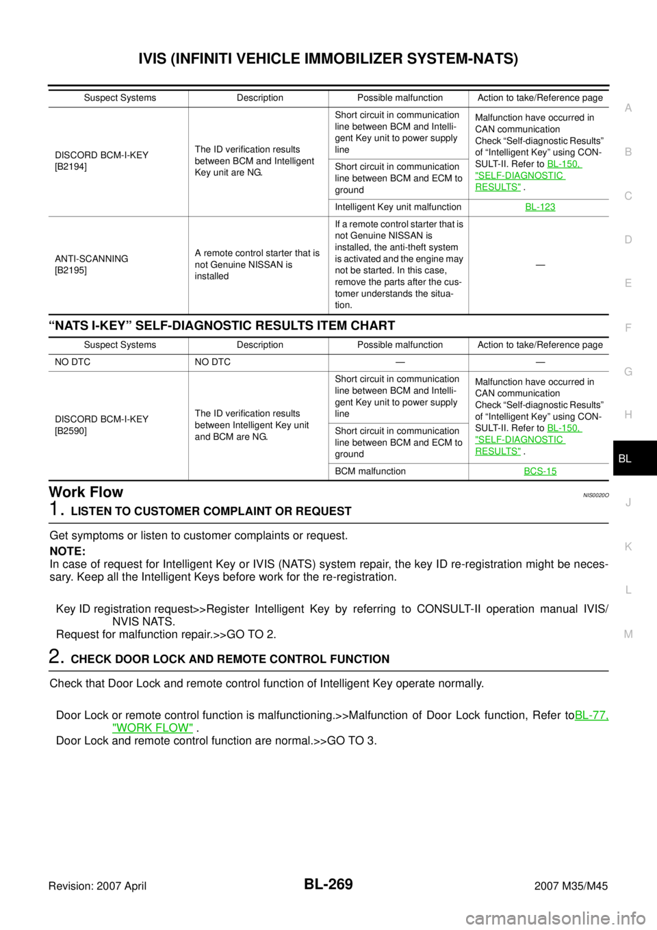
“NATS I-KEY” SELF-DIAGNOSTIC RESULTS ITEM CHART
Work FlowNIS0020O
1. LISTEN TO CUSTOMER COMPLAINT OR REQUEST
Get symptoms or listen to customer complaints or request.
NOTE:
In case of request for Intelligent Key or IVIS (NATS) system repair, the key ID re-registration might be neces-
sary. Keep all the Intelligent Keys before work for the re-registration.
Key ID registration request>>Register Intelligent Key by referring to CONSULT-II operation manual IVIS/
NVIS NATS.
Request for malfunction repair.>>GO TO 2.
2. CHECK DOOR LOCK AND REMOTE CONTROL FUNCTION
Check that Door Lock and remote control function of Intelligent Key operate normally.
Door Lock or remote control function is malfunctioning.>>Malfunction of Door Lock function, Refer toBL-77,
"WORK FLOW" .
Door Lock and remote control function are normal.>>GO TO 3.
DISCORD BCM-I-KEY
[B2194]The ID verification results
between BCM and Intelligent
Key unit are NG.Short circuit in communication
line between BCM and Intelli-
gent Key unit to power supply
lineMalfunction have occurred in
CAN communication
Check “Self-diagnostic Results”
of “Intelligent Key” using CON-
SULT-II. Refer to BL-150,
"SELF-DIAGNOSTIC
RESULTS" . Short circuit in communication
line between BCM and ECM to
ground
Intelligent Key unit malfunctionBL-123
ANTI-SCANNING
[B2195]A remote control starter that is
not Genuine NISSAN is
installedIf a remote control starter that is
not Genuine NISSAN is
installed, the anti-theft system
is activated and the engine may
not be started. In this case,
remove the parts after the cus-
tomer understands the situa-
tion.— Suspect Systems Description Possible malfunction Action to take/Reference page
Suspect Systems Description Possible malfunction Action to take/Reference page
NO DTC NO DTC — —
DISCORD BCM-I-KEY
[B2590]The ID verification results
between Intelligent Key unit
and BCM are NG.Short circuit in communication
line between BCM and Intelli-
gent Key unit to power supply
lineMalfunction have occurred in
CAN communication
Check “Self-diagnostic Results”
of “Intelligent Key” using CON-
SULT-II. Refer to BL-150,
"SELF-DIAGNOSTIC
RESULTS" . Short circuit in communication
line between BCM and ECM to
ground
BCM malfunctionBCS-15