Page 603 of 4647
ATC-152
REFRIGERANT LINES
Revision: 2007 April2007 M35/M45
ComponentsNJS000HN
Refer to AT C - 7 , "Precautions for Refrigerant Connection" .
VQ35DE
SJIA1700E
Page 740 of 4647
![INFINITI M35 2007 Factory Service Manual TROUBLE DIAGNOSIS
AV-115
[WITHOUT MOBILE ENTERTAINMENT SYSTEM]
C
D
E
F
G
H
I
J
L
MA
B
AV
Revision: 2007 April2007 M35/M45
Warning Message of Whether Rear View Image Is Rolling or Not DisplayedNKS00495](/manual-img/42/57024/w960_57024-739.png "INFINITI M35 2007 Factory Service Manual TROUBLE DIAGNOSIS
AV-115
[WITHOUT MOBILE ENTERTAINMENT SYSTEM]
C
D
E
F
G
H
I
J
L
MA
B
AV
Revision: 2007 April2007 M35/M45
Warning Message of Whether Rear View Image Is Rolling or Not DisplayedNKS00495")
TROUBLE DIAGNOSIS
AV-115
[WITHOUT MOBILE ENTERTAINMENT SYSTEM]
C
D
E
F
G
H
I
J
L
MA
B
AV
Revision: 2007 April2007 M35/M45
Warning Message of Whether Rear View Image Is Rolling or Not DisplayedNKS00495
1. CHECK HARNESS BETWEEN AV (NAVI) CONTROL UNIT AND FRONT DISPLAY UNIT
1. Disconnect AV (NAVI) control unit connector and front display unit connector.
2. Check continuity between AV (NAVI) control unit harness con-
nector (A) M210 terminals 51, 52 and display unit harness con-
nector (B) M203 terminals 4, 6.
3. Check continuity between AV (NAVI) control unit harness con-
nector (A) M210 terminals 51, 52 and ground.
OK or NG
OK >> GO TO 2.
NG >> Repair harness or connector.
2. CHECK HORIZONTAL SYNCHRONIZING SIGNAL
1. Connect AV (NAVI) control unit connector and front display unit connector.
2. Turn ignition switch ON.
3. Check signal between AV (NAVI) control unit harness connector
M210 terminal 51 and ground.
OK or NG
OK >> GO TO 3.
NG >> Replace front display unit.
3. CHECK VERTICAL SYNCHRONIZING SIGNAL
Check signal between AV (NAVI) control unit harness connector
M210 terminal 52 and ground.
OK or NG
OK >> Replace AV (NAVI) control unit.
NG >> Replace front display unit.
DVD Operation Screen Is Not DisplayedNKS00496
Refer to AV- 11 5 , "Warning Message of Whether Rear View Image Is Rolling or Not Displayed" .
It Cannot Be Switched to DVD ModeNKS00497
Refer to AV- 11 6 , "DVD SOUND IS NOT OUTPUT" . 51 – 4 : Continuity should exist.
52 – 6 : Continuity should exist.
51, 52 – Ground : Continuity should not exist.
SKIB4698E
51 – Ground:
SKIB4699E
SKIB3601E
52 – Ground:
SKIB4700E
SKIB3598E
Page 890 of 4647
![INFINITI M35 2007 Factory Service Manual TROUBLE DIAGNOSIS
AV-265
[WITH MOBILE ENTERTAINMENT SYSTEM]
C
D
E
F
G
H
I
J
L
MA
B
AV
Revision: 2007 April2007 M35/M45
6. CHECK VERTICAL SYNCHRONIZING SIGNAL
Check signal between AV (NAVI) control uni](/manual-img/42/57024/w960_57024-889.png "INFINITI M35 2007 Factory Service Manual TROUBLE DIAGNOSIS
AV-265
[WITH MOBILE ENTERTAINMENT SYSTEM]
C
D
E
F
G
H
I
J
L
MA
B
AV
Revision: 2007 April2007 M35/M45
6. CHECK VERTICAL SYNCHRONIZING SIGNAL
Check signal between AV (NAVI) control uni")
TROUBLE DIAGNOSIS
AV-265
[WITH MOBILE ENTERTAINMENT SYSTEM]
C
D
E
F
G
H
I
J
L
MA
B
AV
Revision: 2007 April2007 M35/M45
6. CHECK VERTICAL SYNCHRONIZING SIGNAL
Check signal between AV (NAVI) control unit harness connector
M210 terminal 52 and ground.
OK or NG
OK >> Replace AV (NAVI) control unit.
NG >> Replace video distributor.
DVD Operation Screen Is Not DisplayedNKS004B8
ONLY FRONT DISPLAY
Refer to AV- 2 6 3 , "Warning Message of Whether Rear View Image Is Rolling or Not Displayed" .
ONLY REAR DISPLAY
1. CHECK HARNESS BETWEEN VIDEO DISTRIBUTOR AND REAR DISPLAY UNIT
1. Disconnect video distributor connector and rear display unit connector.
2. Check continuity between video distributor harness connector
(A) M206 terminals 29, 30 and rear display unit harness connec-
tor (B) R102 terminals 19, 20.
3. Check continuity between AV (NAVI) control unit harness con-
nector (A) M206 terminals 29, 30 and ground.
OK or NG
OK >> GO TO 2.
NG >> Repair harness or connector.
2. CHECK VERTICAL SYNCHRONIZING SIGNAL
1. Connect video distributor connector and rear display unit connector.
2. Turn ignition switch ON.
3. Check signal between video distributor harness connector M206
terminal 29 and ground.
OK or NG
OK >> GO TO 3.
NG >> Replace rear display unit.52 – Ground:
SKIB4700E
SKIB3598E
29 – 19 : Continuity should exist.
30 – 20 : Continuity should exist.
29, 30 – Ground : Continuity should not exist.
SKIB4829E
29 – Ground:
SKIB4830E
SKIB3598E
Page 1170 of 4647
 SYSTEM
BL-237
C
D
E
F
G
H
J
K
L
MA
B
BL
Revision: 2007 April2007 M35/M45
HOOD SWITCH CHECK
1. CHECK HOOD SWITCH
Check hood switch and hood fitting condition.
OK or NG")
VEHICLE SECURITY (THEFT WARNING) SYSTEM
BL-237
C
D
E
F
G
H
J
K
L
MA
B
BL
Revision: 2007 April2007 M35/M45
HOOD SWITCH CHECK
1. CHECK HOOD SWITCH
Check hood switch and hood fitting condition.
OK or NG
OK >> GO TO 2.
NG >> Adjust installation of hood switch.
2. CHECK HOOD SWITCH INPUT SIGNAL
With CONSULT-II
Check (“HOOD SW”) in “DATA MONITOR” mode with CONSULT-II.
�When hood is opened:
�When hood is closed:
Without CONSULT-II
Check voltage between IPDM E/R connector and ground.
OK or NG
OK >> Hood switch is OK, and go to BL-239, "TRUNK ROOM
LAMP SWITCH CHECK" .
NG >> GO TO 3.
3. CHECK HOOD SWITCH
1. Turn ignition switch OFF.
2. Disconnect hood switch connector.
3. Check continuity between hood switch terminals 1 and 2.
OK or NG
OK >> GO TO 4.
NG >> Replace hood switch.HOOD SW : ON
HOOD SW : OFF
PIIA7006E
IPDM E/R con-
nectorTe r m i n a l s
Condition of hoodVoltage [V]
(Approx.)
(+) (-)
E9 60 GroundOPEN 0
CLOSE Battery voltage
PIIB6214E
Hood
switchTerminalsCondition of hood
switchContinuity
E44 1 2Pressed No
Released Yes
PIIB6215E
Page 1174 of 4647
 SYSTEM
BL-241
C
D
E
F
G
H
J
K
L
MA
B
BL
Revision: 2007 April2007 M35/M45
Diagnostic Procedure 2NIS00206
SECURITY INDICATOR LAMP CHECK
1. SECURITY INDICATOR LAMP ACTIVE")
VEHICLE SECURITY (THEFT WARNING) SYSTEM
BL-241
C
D
E
F
G
H
J
K
L
MA
B
BL
Revision: 2007 April2007 M35/M45
Diagnostic Procedure 2NIS00206
SECURITY INDICATOR LAMP CHECK
1. SECURITY INDICATOR LAMP ACTIVE TEST
With CONSULT-II
Check (“THEFT IND”) in “ACTIVE TEST” mode with CONSULT-II.
OK or NG
OK >> Security indicator lamp is OK.
NG >> GO TO 2.
2. CHECK HARNESS CONTINUITY
1. Turn ignition switch OFF.
2. Disconnect security indicator lamp connector.
3. Check voltage between multi-function switch (security indicator
lamp) connector and ground.
OK or NG
OK >> Check the following.
�Harness for open or short between BCM and multi-
function switch (security indicator lamp)
�Security indicator lamp condition
NG >> Check the following.
�15A fuse [No.37, located in fuse block (J/B)]
�Harness for open or short between multi-function switch (security indicator lamp) and fuse Perform operation shown on display indicator lamp
should illuminate.
PIIA7005E
Terminals
Voltage (V)
(Approx.) (+)
(–)
Security indicator
lamp connectorTerminal
M69 1 Ground Battery voltage
PIIB6218E
Page 1207 of 4647

Revision: 2007 April2007 M35/M45
Symptom Chart for Security IndicatorNIS0020Q
Security indicator does not turn ON or flash.
CAUTION:
�Follow Trou")
BL-274
IVIS (INFINITI VEHICLE IMMOBILIZER SYSTEM-NATS)
Revision: 2007 April2007 M35/M45
Symptom Chart for Security IndicatorNIS0020Q
Security indicator does not turn ON or flash.
CAUTION:
�Follow Trouble Diagnosis Flowchart referring to “Diagnosis Procedure”. Determine malfunction-
ing condition before performing this diagnosis.
�Make sure that vehicle is under the condition shown in “Conditions of vehicle” before starting
diagnosis.
�Check systems shown in the “Action” column in this order.
CONDITIONS OF VEHICLE (OPERATING CONDITIONS)
�Intelligent Key is not inserted into key slot.
�Engine switch is not depressed.
Check Security Indicator HarnessNIS0020R
1. SECURITY INDICATOR LAMP ACTIVE TEST
With CONSULT-II
Check (“THEFT IND”) in “ACTIVE TEST” mode with CONSULT-II.
OK or NG
OK >> Security indicator lamp is OK.
NG >> GO TO 2.
Action Reference page
1. Check security indicator harnessBL-274
2. Replace BCMBCS-15
Perform operation shown on display indicator lamp
should illuminate.
PIIA7005E
Page 1249 of 4647
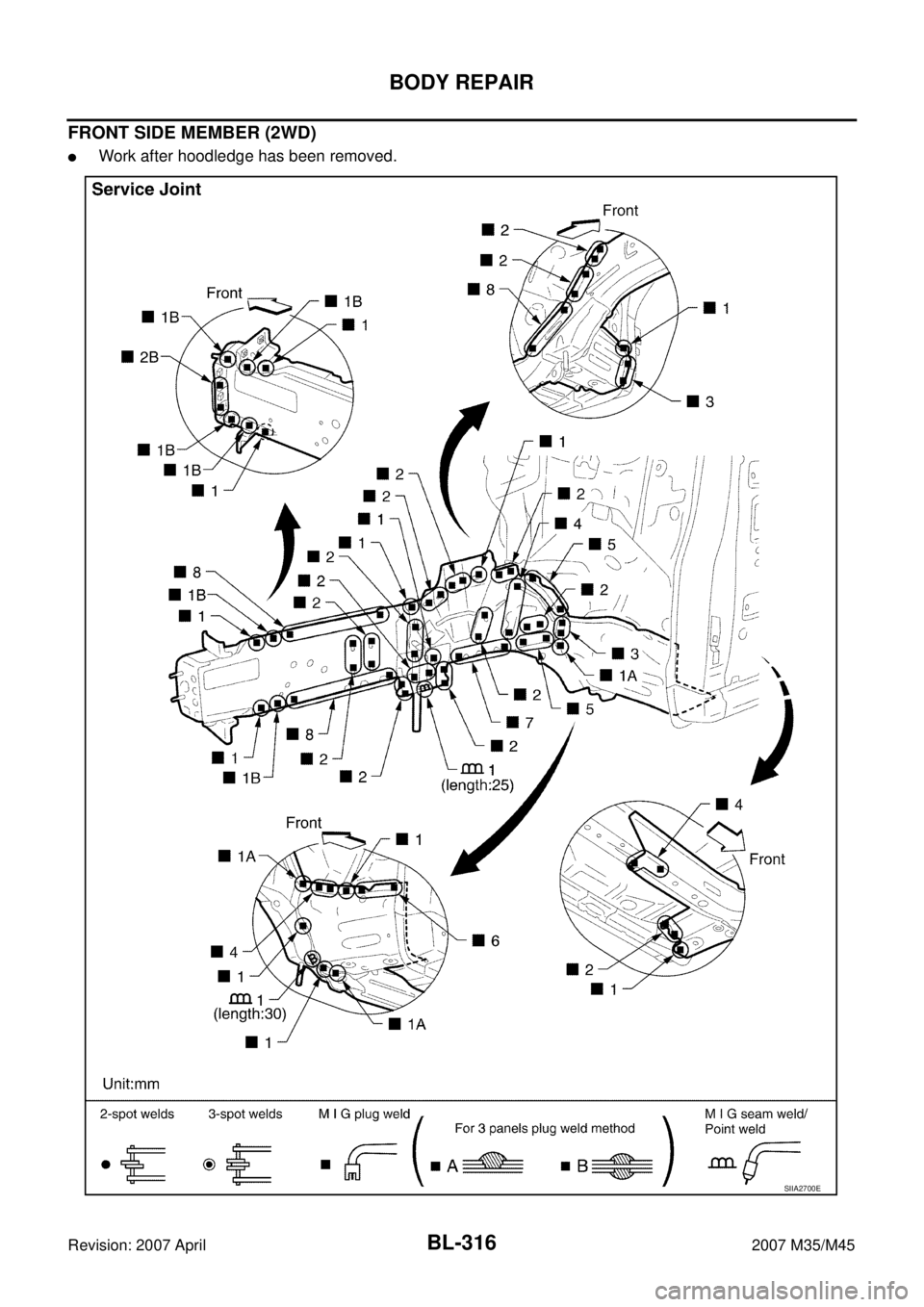
BL-316
BODY REPAIR
Revision: 2007 April2007 M35/M45
FRONT SIDE MEMBER (2WD)
�Work after hoodledge has been removed.
SIIA2700E
Page 1294 of 4647

FRONT DISC BRAKE
BR-27
C
D
E
G
H
I
J
K
L
MA
B
BR
Revision: 2007 April2007 M35/M45
DISC ROTOR INSPECTION
Visual Inspection
Check surface of disc rotor for uneven wear, cracks, and serious damage. Replace if there are.
Runout Inspection
1. Fix disc rotor to wheel hub using wheel nuts (2 or more posi-
tions).
2. Inspect runout using a dial gauge. [Measured at 10 mm (0.39 in)
inside the disc edge.]
NOTE:
Before measuring, make sure that wheel bearing axial end play
is within the specification. Refer to FAX-5, "
WHEEL BEARING
INSPECTION" .
3. When runout exceeds limit value, displace mounting positions of
disc rotor by one hole. And then find a position of the minimum value for runout.
4. Replace or lathe disc rotor if runout is outside the specified value after performing the above operation.
(“MAD DL-8700”, “AMMCO 700 and 705” or equivalent.)
Thickness Inspection
Check thickness of the disc rotor using a micrometer. Replace disc
rotor if thickness is under the wear limit.
BRAKE BURNISHING PROCEDURE
Burnish contact surfaces between disc rotors and pads according to following procedure after refinishing or
replacing rotors, after replacing pads, or if a soft pedal occurs at very low mileage.
CAUTION:
�Be careful of vehicle speed because the brake does not operate easily until pad and disc rotor are
securely fitted.
�Only perform this procedure under safe road and traffic conditions. Use extreme caution.
1. Drive vehicle on straight, flat road.
2. Depress brake pedal with the power to stop vehicle within 3 to 5 seconds until the vehicle stops.
3. Drive without depressing brake for a few minutes to cool the brake.
4. Repeat steps 1 to 3 until pad and disc rotor are securely fitted.Runout limit : 0.035 mm (0.0014 in)
(with it attached to the vehicle)
BRA0580D
Standard thickness : 28.0 mm (1.102 in)
Wear limit : 26.0 mm (1.024 in)
Thickness variation
(Measured at 8 positions): 0.015 mm (0.0006 in)
SBR020B