Page 4415 of 4647
SRS-34
TROUBLE DIAGNOSIS
Revision: 2007 April2007 M35/M45
PASS A/B INDCTR
CKT
[B1023]�Front passenger air bag off indicator or related circuit is mal-
functioning.1. Visually check the wiring harness
connection.
2. Replace the harness if it has visible
damage.
3. Replace front passenger air bag off
indicator (The installation position is
an overhead consoul).
4. Replace the diagnosis sensor unit.
5. Replace the related harness.
FRONTAL COLLISION
DETECTION
[B1209]
�Seat belt pre-tensioner and front air bag are deployed.�Go to SRS-54, "For Frontal Colli-
sion" .
SIDE COLLISION
DETECTION
[B1210]
�Side and curtain air bag is deployed.�Go to SRS-56, "For Side Collision" . Diagnostic item ExplanationRepair order
“Recheck SRS at each replacement”
Page 4420 of 4647

TROUBLE DIAGNOSIS
SRS-39
C
D
E
F
G
I
J
K
L
MA
B
SRS
Revision: 2007 April2007 M35/M45
Trouble Diagnosis: “AIR BAG” Warning Lamp Does Not Turn OFFNHS00099
DIAGNOSTIC PROCEDURE 7
1. CHECK THE DEPLOYMENT OF AIR BAG MODULE
Is air bag module deployed?
YES or NO
YES >> Refer to SRS-54, "COLLISION DIAGNOSIS" .
NO >> GO TO 2.
2. CHECK THE AIR BAG FUSE
Check 10A fuse [No.13, located in fuse block (J/B)].
Refer to PG-3, "
POWER SUPPLY ROUTING CIRCUIT" .
OK or NG
OK >> GO TO 4.
NG >> GO TO 3.
3. CHECK AIR BAG FUSE AGAIN
Replace “AIR BAG” fuse and turn ignition switch ON.
Does the
“AIR BAG” fuse blow again?
YES >> Repair or replace main harness.
NO >>INSPECTION END
4. CHECK DIAGNOSIS SENSOR UNIT
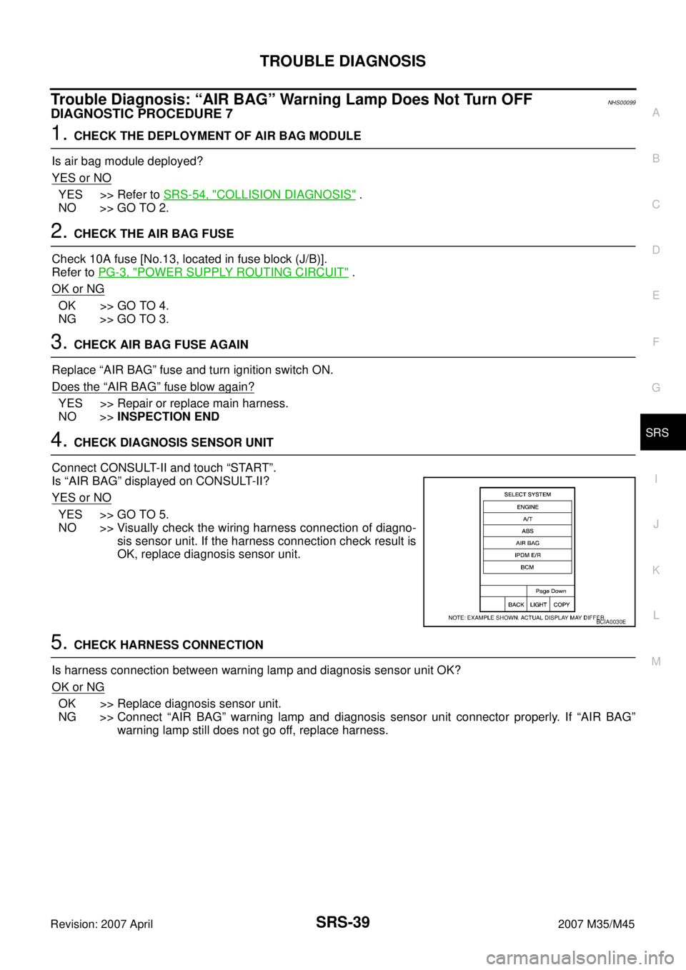
Connect CONSULT-II and touch “START”.
Is “AIR BAG” displayed on CONSULT-II?
YES or NO
YES >> GO TO 5.
NO >> Visually check the wiring harness connection of diagno-
sis sensor unit. If the harness connection check result is
OK, replace diagnosis sensor unit.
5. CHECK HARNESS CONNECTION
Is harness connection between warning lamp and diagnosis sensor unit OK?
OK or NG
OK >> Replace diagnosis sensor unit.
NG >> Connect “AIR BAG” warning lamp and diagnosis sensor unit connector properly. If “AIR BAG”
warning lamp still does not go off, replace harness.
BCIA0030E
Page 4421 of 4647
SRS-40
TROUBLE DIAGNOSIS
Revision: 2007 April2007 M35/M45
Trouble Diagnosis: “AIR BAG” Warning Lamp Does Not Turn ONNHS0009A
DIAGNOSTIC PROCEDURE 8
1. CHECK METER FUSE
Check 10A fuse [No.14, located in fuse block (J/B)].
Refer to PG-3, "
POWER SUPPLY ROUTING CIRCUIT" .
OK or NG
OK >> GO TO 3.
NG >> GO TO 2.
2. CHECK METER FUSE AGAIN
Replace 10A fuse [No.14, located in fuse block (J/B)] and turn ignition switch ON.
Does the meter fuse blow again?
YES >> Repair or replace the related harness.
NO >>INSPECTION END
3. CHECK HARNESS CONNECTION BETWEEN DIAGNOSIS SENSOR UNIT AND COMBINATION
METER
Disconnect diagnosis sensor unit connector and turn ignition switch ON.
Does “AIR BAG” warning lamp turn ON?
YES or NO
YES >> Replace diagnosis sensor unit.
NO >> Replace combination meter assembly.
Page 4422 of 4647

TROUBLE DIAGNOSIS
SRS-41
C
D
E
F
G
I
J
K
L
MA
B
SRS
Revision: 2007 April2007 M35/M45
Trouble Diagnosis: Passenger Seatbelt Warning SystemNHS0009S
1. CHECK THE SYSTEM 1
Check seatbelt warning lamp function.
Seatbelt warning lamp turns ON in the following conditions.
�Driver seatbelt is fastened.
�Occupant is on passenger seat.
�Passenger seatbelt is not fasten.
OK or NG
OK >> GO TO 2.
NG >> Check the followings.
�Harness between air bag diagnosis sensor unit and combination meter.
�Seatbelt buckle switch (passenger side) circuit.
�Seatbelt buckle switch (passenger side).
If these are OK, replace air bag diagnosis sensor unit.
2. CHECK THE SYSTEM 2
Check seatbelt warning lamp function.
Seatbelt warning lamp turns OFF in the following conditions.
�Driver seatbelt is fastened.
�Occupant is on passenger seat.
�Passenger seatbelt is fastened.
OK or NG
OK >> System is OK.
NG >> Check the followings.
�Seatbelt buckle switch (passenger side) circuit.
�Seatbelt buckle switch (passenger side).
If these are OK, replace air bag diagnosis sensor unit.
Page 4430 of 4647

CRASH ZONE SENSOR
SRS-49
C
D
E
F
G
I
J
K
L
MA
B
SRS
Revision: 2007 April2007 M35/M45
CRASH ZONE SENSORPFP:98531
Removal and InstallationNHS0009G
REMOVAL
CAUTION:
�Before servicing, turn ignition switch OFF, disconnect both battery terminal and wait at least 3
minutes.
�Do not use air tools or electric tools for servicing.
�Do not use old fixing nuts after removal; replace with new nuts.
�Do not make an impact to the crash zone sensor by dropping etc. Replace the crash zone sensor if
it has been dropped or sustained an impact.
�Replace the crash zone sensor of deployed SRS driver air bag and deployed SRS front passenger
air bag.
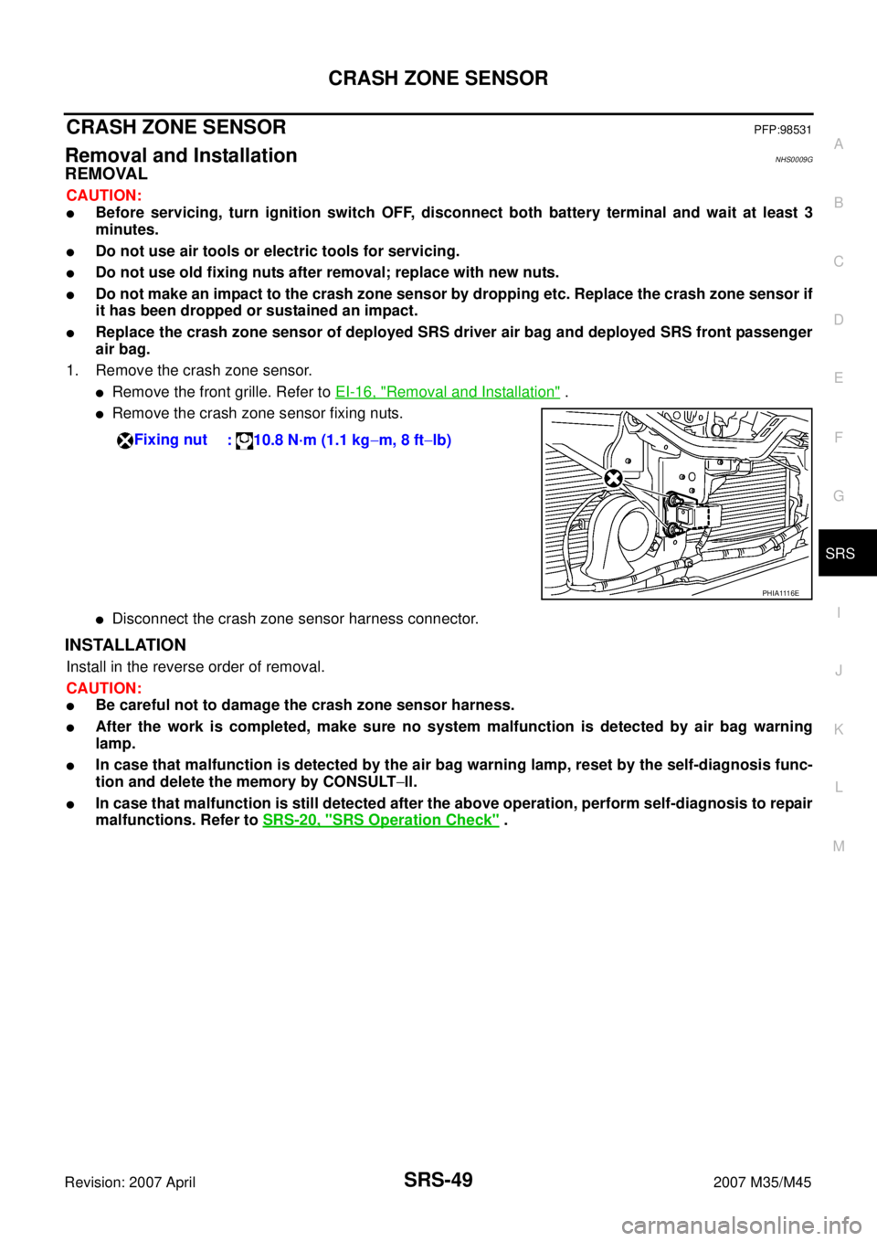
1. Remove the crash zone sensor.
�Remove the front grille. Refer to EI-16, "Removal and Installation" .
�Remove the crash zone sensor fixing nuts.
�Disconnect the crash zone sensor harness connector.
INSTALLATION
Install in the reverse order of removal.
CAUTION:
�Be careful not to damage the crash zone sensor harness.
�After the work is completed, make sure no system malfunction is detected by air bag warning
lamp.
�In case that malfunction is detected by the air bag warning lamp, reset by the self-diagnosis func-
tion and delete the memory by CONSULT−ll.
�In case that malfunction is still detected after the above operation, perform self-diagnosis to repair
malfunctions. Refer to SRS-20, "
SRS Operation Check" . Fixing nut
: 10.8 N·m (1.1 kg−m, 8 ft−lb)
PHIA1116E
Page 4431 of 4647

SRS-50
SIDE AIR BAG (SATELLITE) SENSOR
Revision: 2007 April2007 M35/M45
SIDE AIR BAG (SATELLITE) SENSORPFP:98830
Removal and InstallationNHS0009H
REMOVAL
CAUTION:
�Before servicing, turn ignition switch OFF, disconnect both battery terminal and wait at least 3
minutes.
�Do not use air tools or electric tools for servicing.
�Do not use old fixing nuts after removal; replace with new nuts.
�Do not make an impact to the side air bag (satellite) sensor by dropping etc. Replace the side air
bag (satellite) sensor if it has been dropped or sustained an impact.
�Replace the satellite sensor of deployed SRS front side air bag and deployed SRS side curtain air
bag.
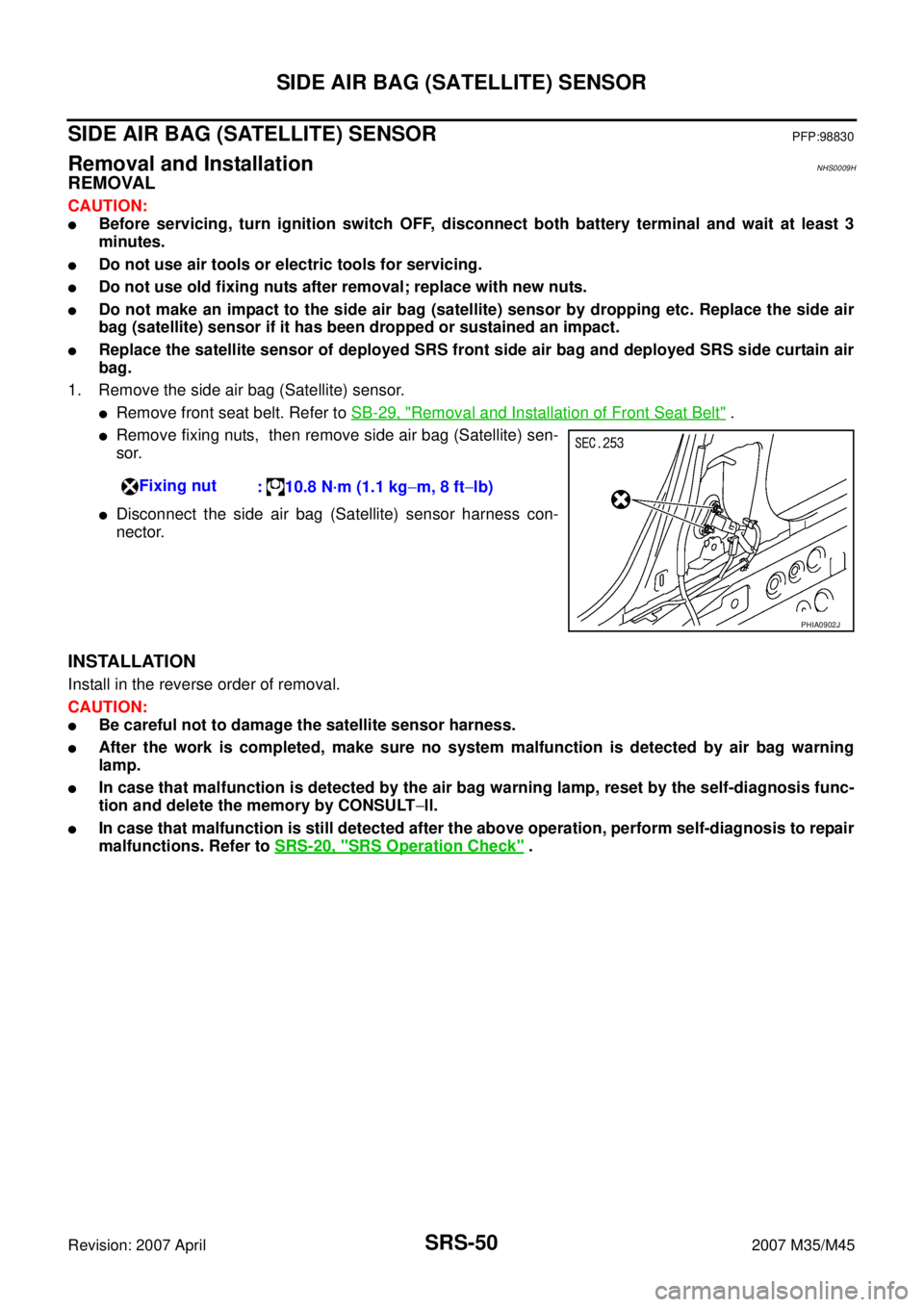
1. Remove the side air bag (Satellite) sensor.
�Remove front seat belt. Refer to SB-29, "Removal and Installation of Front Seat Belt" .
�Remove fixing nuts, then remove side air bag (Satellite) sen-
sor.
�Disconnect the side air bag (Satellite) sensor harness con-
nector.
INSTALLATION
Install in the reverse order of removal.
CAUTION:
�Be careful not to damage the satellite sensor harness.
�After the work is completed, make sure no system malfunction is detected by air bag warning
lamp.
�In case that malfunction is detected by the air bag warning lamp, reset by the self-diagnosis func-
tion and delete the memory by CONSULT−ll.
�In case that malfunction is still detected after the above operation, perform self-diagnosis to repair
malfunctions. Refer to SRS-20, "
SRS Operation Check" . Fixing nut
: 10.8 N·m (1.1 kg−m, 8 ft−lb)
PHIA0902J
Page 4433 of 4647

SRS-52
DIAGNOSIS SENSOR UNIT
Revision: 2007 April2007 M35/M45
DIAGNOSIS SENSOR UNITPFP:28556
Removal and InstallationNHS0009J
REMOVAL
CAUTION:
�Before servicing, turn ignition switch OFF, disconnect both battery terminal and wait at least 3
minutes.
�Before disconnecting the air bag sensor unit harness connector, be sure to disconnect the each
harness connector of the air bag module and pre-tensioner seatbelt to prevent air bag deployment
by static electricity and pre-tensioner seatbelt operation.
�Do not use air tools or electric tools for servicing.
�Do not use old fixing bolts after removal; replace with new bolts.
�Do not make an impact to the diagnosis sensor unit by dropping etc. Replace the diagnosis sen-
sor unit if it has been dropped or sustained an impact.
�Replace the diagnosis sensor unit of deployed SRS air bag and deployed SRS front seat belt pre-
tensioner.
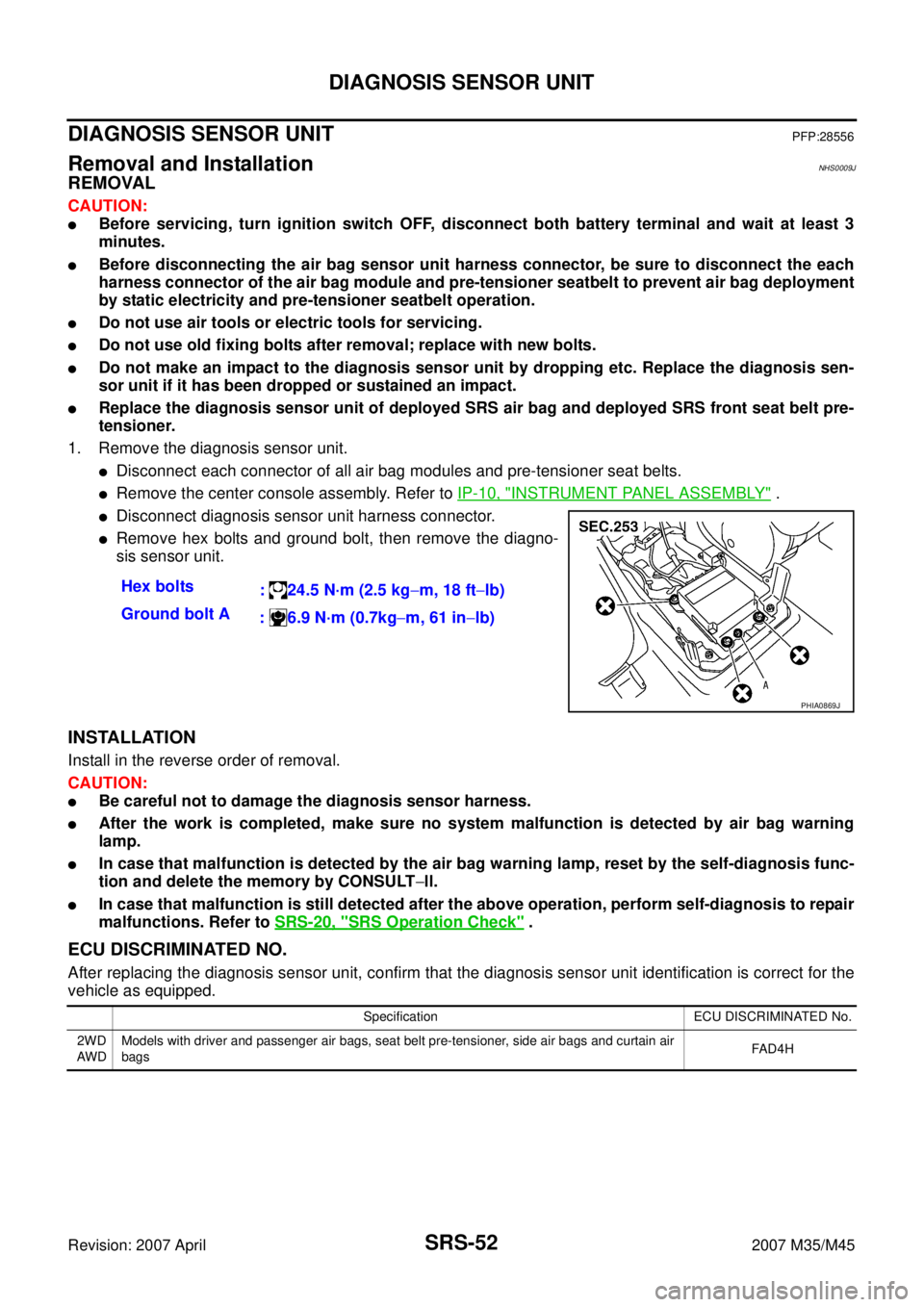
1. Remove the diagnosis sensor unit.
�Disconnect each connector of all air bag modules and pre-tensioner seat belts.
�Remove the center console assembly. Refer to IP-10, "INSTRUMENT PANEL ASSEMBLY" .
�Disconnect diagnosis sensor unit harness connector.
�Remove hex bolts and ground bolt, then remove the diagno-
sis sensor unit.
INSTALLATION
Install in the reverse order of removal.
CAUTION:
�Be careful not to damage the diagnosis sensor harness.
�After the work is completed, make sure no system malfunction is detected by air bag warning
lamp.
�In case that malfunction is detected by the air bag warning lamp, reset by the self-diagnosis func-
tion and delete the memory by CONSULT−ll.
�In case that malfunction is still detected after the above operation, perform self-diagnosis to repair
malfunctions. Refer to SRS-20, "
SRS Operation Check" .
ECU DISCRIMINATED NO.
After replacing the diagnosis sensor unit, confirm that the diagnosis sensor unit identification is correct for the
vehicle as equipped.Hex bolts
: 24.5 N·m (2.5 kg−m, 18 ft−lb)
Ground bolt A
: 6.9 N·m (0.7kg−m, 61 in−lb)
PHIA0869J
Specification ECU DISCRIMINATED No.
2WD
AW DModels with driver and passenger air bags, seat belt pre-tensioner, side air bags and curtain air
bagsFA D 4 H
Page 4434 of 4647
OCCUPANT CLASSIFICATION SYSTEM CONTROL UNIT
SRS-53
C
D
E
F
G
I
J
K
L
MA
B
SRS
Revision: 2007 April2007 M35/M45
OCCUPANT CLASSIFICATION SYSTEM CONTROL UNITPFP:98852
Removal and InstallationNHS0009K
The occupant classification system control unit, seat pressure sensor, and bladder are an integral part of the
front passenger seat cushion and are replaced as an assembly. Refer to SE-166, "
Passenger's Seat Compo-
nents" .