Page 3607 of 4647
![INFINITI M35 2007 Factory Service Manual LT-156
ACTIVE AFS
Revision: 2007 April2007 M35/M45
CAUTION:
�If DTC relating to CAN communication [U1000] and other components are displayed at the same
time, diagnose CAN communication first.
�Make s INFINITI M35 2007 Factory Service Manual LT-156
ACTIVE AFS
Revision: 2007 April2007 M35/M45
CAUTION:
�If DTC relating to CAN communication [U1000] and other components are displayed at the same
time, diagnose CAN communication first.
�Make s](/manual-img/42/57024/w960_57024-3606.png)
LT-156
ACTIVE AFS
Revision: 2007 April2007 M35/M45
CAUTION:
�If DTC relating to CAN communication [U1000] and other components are displayed at the same
time, diagnose CAN communication first.
�Make sure of the normal operation after the parts (except AFS control unit) replacement according
to the self-diagnosis results. Delete the malfunction history.
Display Results
�0: There is malfunction now.
�1 – 39: Displays when it is normal at present and finds malfunction in the past. It increases in order
of 0→1→2...38→39 after returning to the normal condition whenever IGN OFF→ON. If it is over 39,
it is fixed to 39 until the self-diagnostic results are erased. It returns to 0 when malfunction is
detected again in the process.
ECU CIRC
[B2521]Any of several statuses below
�Short circuit exists for 2 seconds or longer on power supply
(approx. 12 V) or ground of swivel position sensor (RH) power
supply (AFS control unit terminal 4).
�Short circuit exists for 2 seconds or longer on power supply
(approx. 12 V) of swivel position sensor (RH) signal (AFS con-
trol unit terminal 9).
�Short circuit exists for 2 seconds or longer on power supply
(approx. 12 V) or ground of swivel position sensor (LH) power
supply (AFS control unit terminal 24).
�Short circuit exists for 2 seconds or longer on power supply
(approx. 12 V) of swivel position sensor (LH) signal (AFS con-
trol unit terminal 29).
�Short circuit exists for 2 seconds or longer on power supply
(approx. 12 V) or ground of height sensor power supply (AFS
control unit terminal 6).
�Short circuit exists for 2 seconds or longer on power supply
(approx. 12 V) of height sensor signal (AFS control unit termi-
nal 28).
�AFS control unit (RAM/ROM) malfunctions.1. Stop the swivel motor RH and
LH when the malfunction
occurred.
2. Stop aiming motors when the
malfunction occurred.
3. Flash at intervals of approx. 1
second when keeping error state
for 2 seconds or longer.
4. Turn ignition switch OFF.LT- 1 7 9 , "
DTC
B2521 ECU
CIRC"
ECM SIG
[B2522]Cannot receive engine speed signal.1. Back to the initial position.
2. Stop when the malfunction
occurred.
3. Flash at intervals of approx. 1
second when keeping error state
for 2 seconds or longer.
4. Turn ignition switch OFF.EC-126,
"SELF-DIAG
RESULTS
MODE".
If above sys-
tem is normal,
replace AFS
control unit.
AFS SIG
[B2523]Cannot transmit AFS off indicator signal.1. Back to the initial position.
2. Normal operation
3. Flashes at intervals of approx. 1
second when keeping error state
for 2 seconds or longer.
4. Turn ignition switch OFF.Replace
AFS control
unit LT- 1 9 2
Details of
error
indication
detected by
CONSULT-
IIConditions of error detectionFail-safe
1. Swivel operation
2. Auto aiming operation
3. AFS OFF indicator operation
4. CancellationReference
Page 3612 of 4647

ACTIVE AFS
LT-161
C
D
E
F
G
H
I
J
L
MA
B
LT
Revision: 2007 April2007 M35/M45
DTC B2503 SWIVEL ACTUATOR RHNKS003QO
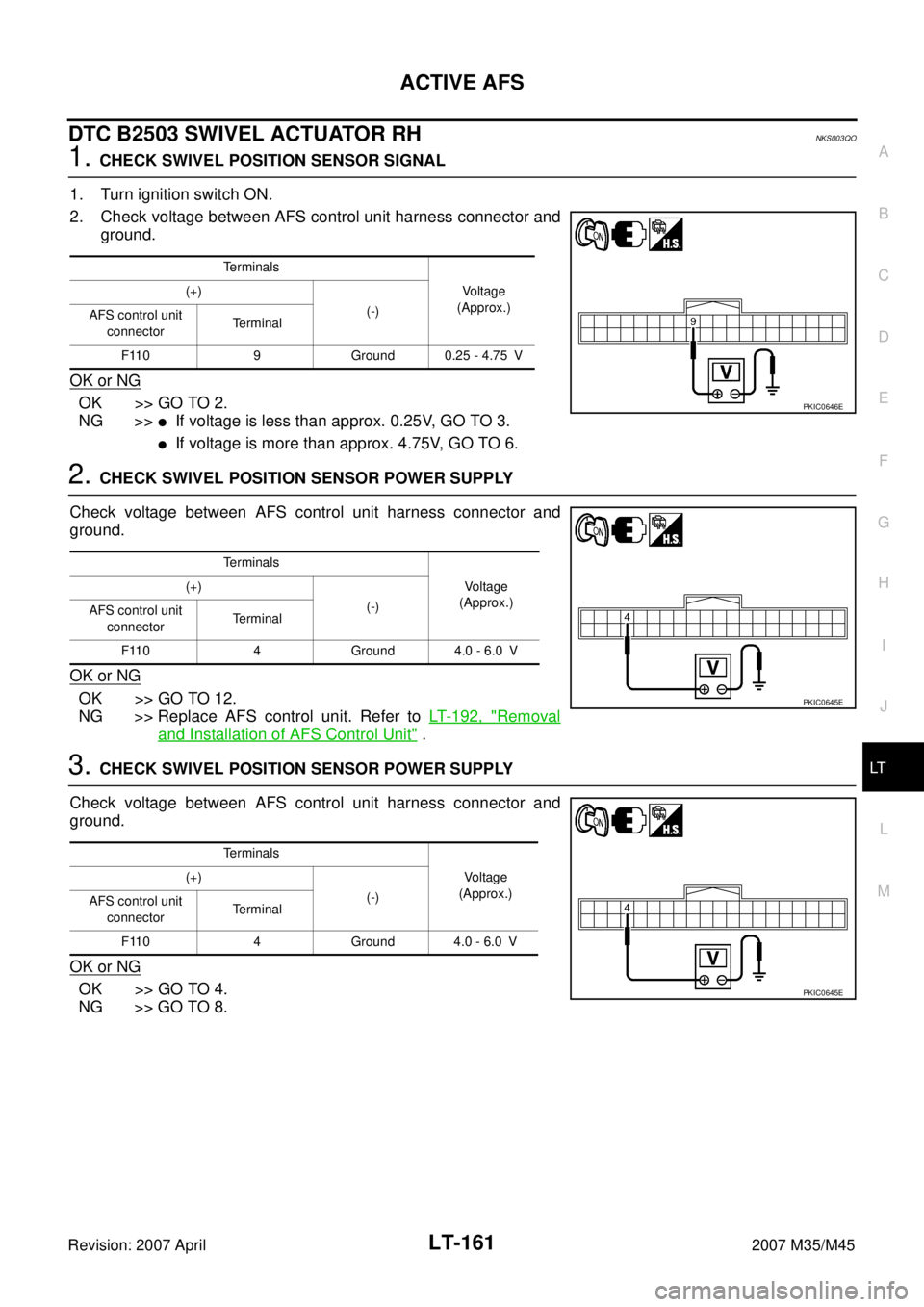
1. CHECK SWIVEL POSITION SENSOR SIGNAL
1. Turn ignition switch ON.
2. Check voltage between AFS control unit harness connector and
ground.
OK or NG
OK >> GO TO 2.
NG >>
�If voltage is less than approx. 0.25V, GO TO 3.
�If voltage is more than approx. 4.75V, GO TO 6.
2. CHECK SWIVEL POSITION SENSOR POWER SUPPLY
Check voltage between AFS control unit harness connector and
ground.
OK or NG
OK >> GO TO 12.
NG >> Replace AFS control unit. Refer to LT- 1 9 2 , "
Removal
and Installation of AFS Control Unit" .
3. CHECK SWIVEL POSITION SENSOR POWER SUPPLY
Check voltage between AFS control unit harness connector and
ground.
OK or NG
OK >> GO TO 4.
NG >> GO TO 8.
Terminals
Voltage
(Approx.) (+)
(-)
AFS control unit
connectorTerminal
F110 9 Ground 0.25 - 4.75 V
PKIC0646E
Terminals
Voltage
(Approx.) (+)
(-)
AFS control unit
connectorTerminal
F110 4 Ground 4.0 - 6.0 V
PKIC0645E
Terminals
Voltage
(Approx.) (+)
(-)
AFS control unit
connectorTerminal
F110 4 Ground 4.0 - 6.0 V
PKIC0645E
Page 3613 of 4647

LT-162
ACTIVE AFS
Revision: 2007 April2007 M35/M45
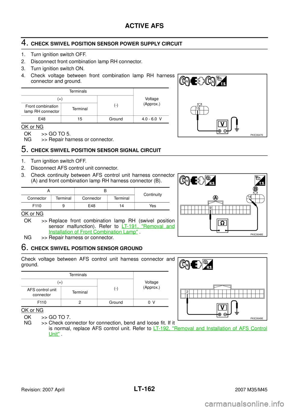
4. CHECK SWIVEL POSITION SENSOR POWER SUPPLY CIRCUIT
1. Turn ignition switch OFF.
2. Disconnect front combination lamp RH connector.
3. Turn ignition switch ON.
4. Check voltage between front combination lamp RH harness
connector and ground.
OK or NG
OK >> GO TO 5.
NG >> Repair harness or connector.
5. CHECK SWIVEL POSITION SENSOR SIGNAL CIRCUIT
1. Turn ignition switch OFF.
2. Disconnect AFS control unit connector.
3. Check continuity between AFS control unit harness connector
(A) and front combination lamp RH harness connector (B).
OK or NG
OK >> Replace front combination lamp RH (swivel position
sensor malfunction). Refer to LT- 1 9 1 , "
Removal and
Installation of Front Combination Lamp" .
NG >> Repair harness or connector.
6. CHECK SWIVEL POSITION SENSOR GROUND
Check voltage between AFS control unit harness connector and
ground.
OK or NG
OK >> GO TO 7.
NG >> Check connector for connection, bend and loose fit. If it
is normal, replace AFS control unit. Refer to LT- 1 9 2 , "
Removal and Installation of AFS Control
Unit" .
Te r m i n a l s
Voltage
(Approx.) (+)
(-)
Front combination
lamp RH connectorTerminal
E48 15 Ground 4.0 - 6.0 V
PKIC0647E
AB
Continuity
Connector Terminal Connector Terminal
F110 9 E48 14 Yes
PKIC0648E
Te r m i n a l s
Voltage
(Approx.) (+)
(-)
AFS control unit
connectorTerminal
F110 2 Ground 0 V
PKIC0649E
Page 3614 of 4647

ACTIVE AFS
LT-163
C
D
E
F
G
H
I
J
L
MA
B
LT
Revision: 2007 April2007 M35/M45
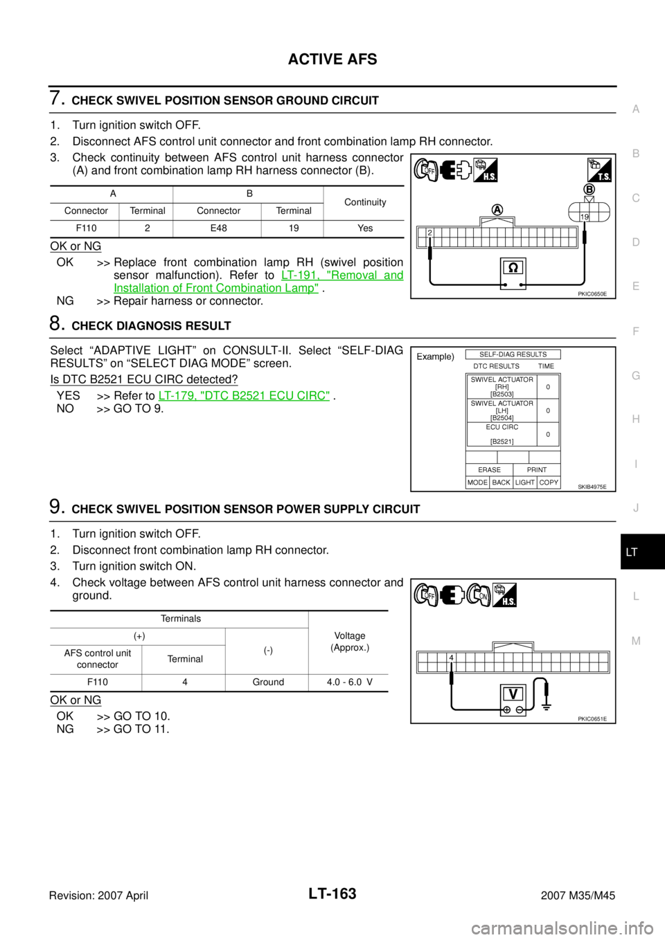
7. CHECK SWIVEL POSITION SENSOR GROUND CIRCUIT
1. Turn ignition switch OFF.
2. Disconnect AFS control unit connector and front combination lamp RH connector.
3. Check continuity between AFS control unit harness connector
(A) and front combination lamp RH harness connector (B).
OK or NG
OK >> Replace front combination lamp RH (swivel position
sensor malfunction). Refer to LT- 1 9 1 , "
Removal and
Installation of Front Combination Lamp" .
NG >> Repair harness or connector.
8. CHECK DIAGNOSIS RESULT
Select “ADAPTIVE LIGHT” on CONSULT-II. Select “SELF-DIAG
RESULTS” on “SELECT DIAG MODE” screen.
Is DTC B2521 ECU CIRC detected?
YES >> Refer to LT- 1 7 9 , "DTC B2521 ECU CIRC" .
NO >> GO TO 9.
9. CHECK SWIVEL POSITION SENSOR POWER SUPPLY CIRCUIT
1. Turn ignition switch OFF.
2. Disconnect front combination lamp RH connector.
3. Turn ignition switch ON.
4. Check voltage between AFS control unit harness connector and
ground.
OK or NG
OK >> GO TO 10.
NG >> GO TO 11.
AB
Continuity
Connector Terminal Connector Terminal
F110 2 E48 19 Yes
PKIC0650E
SKIB4975E
Terminals
Voltage
(Approx.) (+)
(-)
AFS control unit
connectorTerminal
F110 4 Ground 4.0 - 6.0 V
PKIC0651E
Page 3615 of 4647
LT-164
ACTIVE AFS
Revision: 2007 April2007 M35/M45
10. CHECK SWIVEL POSITION SENSOR SIGNAL CIRCUIT (SHORT CIRCUIT)
1. Turn ignition switch OFF.
2. Disconnect AFS control unit connector.
3. Check continuity between AFS control unit harness connector
and ground.
OK or NG
OK >> Replace front combination lamp RH (swivel position
sensor malfunction). Refer to LT- 1 9 1 , "
Removal and
Installation of Front Combination Lamp" .
NG >> Repair harness or connector.
11 . CHECK SWIVEL POSITION SENSOR POWER SUPPLY CIRCUIT (SHORT CIRCUIT)
1. Turn ignition switch OFF.
2. Disconnect AFS control unit connector.
3. Check continuity between AFS control unit harness connector
and ground.
OK or NG
OK >> Replace AFS control unit. Refer to LT- 1 9 2 , "Removal
and Installation of AFS Control Unit" .
NG >> Repair harness or connector.
AFS control unit
connectorTerminal
GroundContinuity
F110 9 No
SKIB4968E
AFS control unit
connectorTerminal
GroundContinuity
F110 4 No
PKIC0652E
Page 3616 of 4647
ACTIVE AFS
LT-165
C
D
E
F
G
H
I
J
L
MA
B
LT
Revision: 2007 April2007 M35/M45
12. CHECK SWIVEL MOTOR
1. Turn ignition switch OFF.
2. Disconnect front combination lamp RH connector.
3. Check continuity between front combination lamp RH connector
terminals.
4. Check continuity between front combination lamp RH connector
terminals.
5. Check continuity between front combination lamp RH connector
terminals (insulation resistance).
OK or NG
OK >> GO TO 13.
NG >> Replace front combination lamp RH (swivel motor mal-
function). Refer to LT- 1 9 1 , "
Removal and Installation of
Front Combination Lamp" .
Front combination lamp RH terminals (1 phase) Resistance
16 20 Approx. 7.4Ω
PKIC0655E
Front combination lamp RH terminals (2 phase) Resistance
17 21 Approx. 7.4Ω
PKIC0656E
Front combination lamp RH terminals Resistance
16 17 Approx. 1 MΩ or more
PKIC0654E
Page 3617 of 4647

LT-166
ACTIVE AFS
Revision: 2007 April2007 M35/M45
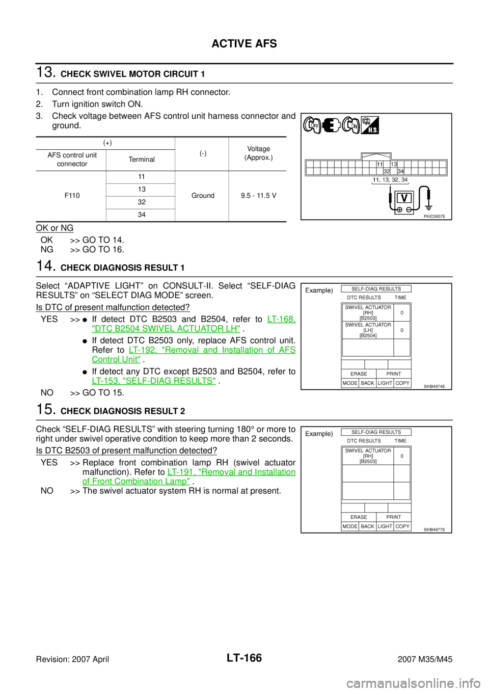
13. CHECK SWIVEL MOTOR CIRCUIT 1
1. Connect front combination lamp RH connector.
2. Turn ignition switch ON.
3. Check voltage between AFS control unit harness connector and
ground.
OK or NG
OK >> GO TO 14.
NG >> GO TO 16.
14. CHECK DIAGNOSIS RESULT 1
Select “ADAPTIVE LIGHT” on CONSULT-II. Select “SELF-DIAG
RESULTS” on “SELECT DIAG MODE” screen.
Is DTC of present malfunction detected?
YES >>�If detect DTC B2503 and B2504, refer to LT- 1 6 8 ,
"DTC B2504 SWIVEL ACTUATOR LH" .
�If detect DTC B2503 only, replace AFS control unit.
Refer to LT- 1 9 2 , "
Removal and Installation of AFS
Control Unit" .
�If detect any DTC except B2503 and B2504, refer to
LT- 1 5 3 , "
SELF-DIAG RESULTS" .
NO >> GO TO 15.
15. CHECK DIAGNOSIS RESULT 2
Check “SELF-DIAG RESULTS” with steering turning 180° or more to
right under swivel operative condition to keep more than 2 seconds.
Is DTC B2503 of present malfunction detected?
YES >> Replace front combination lamp RH (swivel actuator
malfunction). Refer to LT- 1 9 1 , "
Removal and Installation
of Front Combination Lamp" .
NO >> The swivel actuator system RH is normal at present.
(+)
(-)Voltage
(Approx.) AFS control unit
connectorTerminal
F11011
Ground 9.5 - 11.5 V 13
32
34
PKIC0657E
SKIB4974E
SKIB4977E
Page 3618 of 4647
ACTIVE AFS
LT-167
C
D
E
F
G
H
I
J
L
MA
B
LT
Revision: 2007 April2007 M35/M45
16. CHECK SWIVEL MOTOR CIRCUIT 2
1. Turn ignition switch OFF.
2. Disconnect AFS control unit connector and front combination lamp RH connector.
3. Check continuity between AFS control unit harness connector
(A) and front combination lamp RH harness connector (B).
4. Check continuity between AFS control unit harness connector (A) and ground.
OK or NG
OK >> Replace AFS control unit. Refer to LT- 1 9 2 , "Removal and Installation of AFS Control Unit" .
NG >> Repair or replace harness or connector.
AB
Continuity
Connector Terminal Connector Terminal
F11011
E4820
Ye s 13 21
32 17
34 16
PKIC0653E
A
GroundContinuity
Connector Terminal
F11011
No 13
32
34