HARNESS
PG-97
C
D
E
F
G
H
I
J
L
MA
B
PG
Revision: 2007 April2007 M35/M45
PGC/V EC EVAP Canister Purge Volume Control Solenoid Valve
PHASE EC Camshaft Position Sensor (PHASE)
PHSB1 EC Camshaft Position Sensor (PHASE) (Bank 1)
PHSB2 EC Camshaft Position Sensor (PHASE) (Bank 2)
PNP/SW AT Park/Neutral Position Switch
PNP/SW EC Park/Neutral Position Switch
POS EC Crankshaft Position Sensor (CKPS) (POS)
POWER PG Power Supply Routing Circuit
PRE/SE EC EVAP Control System Pressure Sensor
PS/SEN EC Power Steering Pressure Sensor
PSB SB Pre-Crash Seat Belt
R/SEAT SE Auto Return Seat
RAS STC Rear Active Steer
ROOM/L LT Interior Room Lamp
RP/SEN EC Refrigerant Pressure Sensor
SEAT SE Power Seat
SEN/PW EC Sensor Power Supply
SHADE EI Rear Sunshade
SHIFT AT A/T Shift Lock System
SNOWSW EC Snow Mode Switch
SROOF RF Sunroof
SRS SRS Supplemental Restraint System
START SC Starting System
STOP/L LT Stop Lamp
STSIG AT Start Signal Circuit
T/WARN WT Low Tire Pressure Warning System
TAIL/L LT Parking, License and Tail Lamps
TLID BL Trunk Lid Opener
TPS1 EC Throttle Position Sensor (Sensor 1)
TPS2 EC Throttle Position Sensor (Sensor 2)
TPS3 EC Throttle Position Sensor
TRNSCV BL Homelink Universal Transceiver
TURN LT Turn Signal and Hazard Warning Lamp
VDC BRC Vehicle Dynamics Control System
VEHSEC BL Vehicle Security System
VENT/V EC EVAP Canister Vent Control Valve
VIAS EC Variable Induction Air Control System
VIAS/V EC VIAS Control Solenoid Valve
VSSA/T AT Vehicle speed Sensor A/T (Revolution Sensor)
WARN DI Warning Lamps
WINDOW GW Power Window
WIPER WW Front Wiper and Washer Code Section Wiring Diagram Name
RSU-6
REAR SUSPENSION ASSEMBLY
Revision: 2007 April2007 M35/M45
THE ALIGNMENT PROCESS
IMPORTANT:
Use only the alignment specifications listed in this Service Manual.
�When displaying the alignment settings, many alignment machines use “indicators”: (Green/red, plus or
minus, Go/No Go). Do NOT use these indicators.
–The alignment specifications programmed into your machine that operate these indicators may not be cor-
rect.
–This may result in an ERROR.
�Some newer alignment machines are equipped with an optional “Rolling Compensation” method to “com-
pensate” the sensors (alignment targets or head units). DO NOT use this “Rolling Compensation”
method.
–Use the “Jacking Compensation Method”. After installing the alignment targets or head units, raise the
vehicle and rotate the wheels 1/2 turn both ways.
–See Instructions in the alignment machine you're using for more information on this.
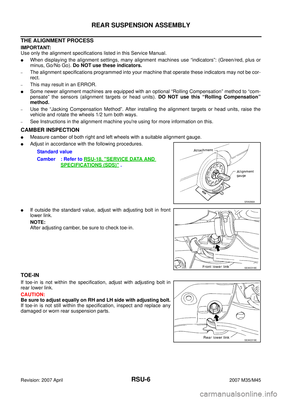
CAMBER INSPECTION
�Measure camber of both right and left wheels with a suitable alignment gauge.
�Adjust in accordance with the following procedures.
�If outside the standard value, adjust with adjusting bolt in front
lower link.
NOTE:
After adjusting camber, be sure to check toe-in.
TOE-IN
If toe-in is not within the specification, adjust with adjusting bolt in
rear lower link.
CAUTION:
Be sure to adjust equally on RH and LH side with adjusting bolt.
If toe-in is not still within the specification, inspect and replace any
damaged or worn rear suspension parts.Standard value
Camber : Refer to RSU-18, "
SERVICE DATA AND
SPECIFICATIONS (SDS)" .
SRA096A
SEIA0318E
SEIA0319E
AWD SYSTEM
TF-11
C
E
F
G
H
I
J
K
L
MA
B
TF
Revision: 2007 April2007 M35/M45
ELECTRIC CONTROLLED COUPLING
Operation Principle
1. AWD control unit supplies command current to electric controlled coupling (AWD solenoid).
2. Control clutch is engaged by electromagnet and torque is detected in control clutch.
3. The cam operates in response to control clutch torque and applies pressure to main clutch.
4. Main clutch transmits torque to front wheels according to pressing power.
�Transmission torque to front wheels is determined according
to command current.
AWD CONTROL UNIT
�Controls distribution of drive power between rear-wheel drive
(0:100) and AWD (50:50) conditions according to signals from
sensors.
�Self-diagnosis can be done with CONSULT-II.
SDIA2270E
SDIA1844E
SDIA3133E

PHSB1 EC Camshaft Position")