Page 3729 of 4366

CHASSIS AND BODY MAINTENANCE MA-37
C
D E
F
G H
I
J
K
M A
B
MA
Revision: 2006 July 2007 FX35/FX45
Checking Power Steering Fluid and LinesNLS00070
Check fluid level in reservoir tank with engine off.
Use “HOT” range at fluid temperatures of 50 to 80 °C (122 to 176 °F)
or “COLD” range at fluid temperatures of 0 to 30 °C (32 to 86 °F).
CAUTION:
�Do not overfill.
�Recommended fluid is Genuine NISSAN PSF or equivalent.
Refer to MA-12, "
RECOMMENDED FLUIDS AND LUBRI-
CANTS"
�Check lines for improper attachment, leaks, cracks, dam-
age, loose connections, chafing and deterioration.
�Check rack boots for accumulation of power steering fluid.
Axle and Suspension PartsNLS00071
Check front and rear axle and suspension parts for excessive play,
cracks, wear or other damage.
�Shake each wheel to check for excessive play.
�Check wheel bearings for smooth operation.
�Check axle and suspension nuts and bolts for looseness.
�Check strut (shock absorber) for oil leakage or other damage.
�Check suspension ball joint for grease leakage and ball joint
dust cover for cracks or other damage.
SST850C
SST851C
SMA525A
SFA392B
Page 3865 of 4366
 to ball stud axially. Use a dial
g")
POWER STEERING GEAR AND LINKAGE PS-25
C
D E
F
H I
J
K L
M A
B
PS
Revision: 2006 July 2007 FX35/FX45
Axial End Play
�Apply load of 490 N (50 kg, 110 lb) to ball stud axially. Use a dial
gauge to measure the amount of the movement that the stud
makes. Check if the reading is within the specified below. If the
value is outside the standard, replace outer and inner sockets.
ASSEMBLY
1. Apply recommended fluid to O-ring. Put an O-ring into rack Teflon ring.
2. Heat rack Teflon ring to approximately 40 °C (104 °F) with a
dryer. Assemble it to mounting groove of rack.
3. To fit rack Teflon ring on rack, use rack Teflon ring installation tool (SST) from tooth side. Compress rim of ring with the tool.
4. Apply recommended grease to rack oil seal. Insert rack oil seal, then insert rack assembly to gear housing assembly.
CAUTION:
�When inserting rack assembly, do not damage retainer
sliding part. If it is damaged, replace gear housing
assembly.
�When inserting rack assembly, do not damage cylinder
inner wall. If it is damaged, it may cause oil leaks.
Replace gear housing assembly.
�Attach rack oil seal. Both inner lip and outer lip should
face each other.
Outer socket 0.5 mm (0.02 in) or less
Inner socket 0.2 mm (0.01 in) or less
SGIA0057E
SGIA0153E
SGIA0154E
SGIA0205E
Page 3866 of 4366
 × 100 mm (3.94 in) around rack")
PS-26
POWER STEERING GEAR AND LINKAGE
Revision: 2006 July 2007 FX35/FX45
a. To avoid damaging inner rack oil seal, wrap an OHP sheet
[approximately. 70 mm (2.76 in) × 100 mm (3.94 in) around rack
tooth. Place oil seal on sheet. Then, pull oil seal along with OHP
sheet until they pass the toothed section of rack, then remove it.
b. Insert rack oil seal (inner) to piston (rack Teflon ring) position and push retainer to adjust screw side with fingers lightly, and
then make rack move in gear housing assembly, install rack oil
seal (inner) to fit with gear housing assembly.
c. When installing outer rack oil seal, cover the end of rack with an OHP sheet [70 mm (2.76 in) × 100 mm (3.94 in)]. It will avoid
damaging rack oil seal. Then place oil seal on sheet. Pull rack oil
seal along with OHP sheet until they pass rack end. Then
remove OHP sheet.
d. Install end cover assembly to rack, move it to gear housing assembly.
5. Using a 45 mm (1.77 in) open head (suitable tool), tighten end cover assembly at the specified torque.
CAUTION:
Do not damage rack surface. If it is damaged, it may cause
oil leaks. Replace rack assembly.
6. After tightening end cover assembly, caulk cylinder at one point as shown in the figure using a punch. This will prevent end cover
from getting loose.
7. Install pinion assembly to gear housing assembly. CAUTION:
In order to protect oil seal from any damage, insert pinion
assembly out straightly.
8. Apply recommended fluid to O-ring. Install O-ring to rear cover.
9. Use a rear cover wrench (SST), install rear cover to gear hous- ing assembly.
SGIA0155E
SGIA0548E
SGIA0157E
SST081B
SGIA0158E
Page 3874 of 4366

PS-34
POWER STEERING OIL PUMP
Revision: 2006 July 2007 FX35/FX45
5. Remove cam ring, rotor, vane, front side plate, flow control valve
A, spring, flow control valve B assembly and O-ring from body
assembly.
CAUTION:
Be careful not to drop and deform flow control valve A and
flow control valve B assembly.
6. Remove suction pipe from body assembly.
7. Remove O-ring from suction pipe.
8. Remove bracket from body assembly.
INSPECTION AFTER DISASSEMBLY
Body Assembly and Rear Cover Inspection
Check body assembly and rear cover for internal damage. Replace rear cover if it is damaged. Replace oil
pump assembly if body assembly is damaged.
Cartridge Assembly Inspection
Check cam ring, rotor and vane for damage. Replace cartridge assembly if necessary.
Side Plate Inspection
Check side plate (front and rear) for damage. Side plate (front and rear) must be replaced as a set if they are
damaged.
Flow Control Valve Inspection
Check flow control valve A, flow control valve spring and flow control valve B assembly for damage. Replace if
there are.
ASSEMBLY
NOTE:
Fix oil pump in vise as occasion demands.
CAUTION:
When retaining drive shaft in a vise, always use copper or aluminum plates between vise and shaft.
1. Apply recommended grease to oil seal lips. Apply recommended fluid to around oil seal, and then install oil seal to body assembly
using the drift [SST].
2. If dowel pin has been removed, insert it into body assembly by hand. If it cannot be inserted by hand, lightly tap with a hammer.
3. Install flow control valve A, flow control valve spring and flow control valve B assembly to locations shown in the figure.
SGIA0526E
SGIA0527E
SGIA0526E
Page 3876 of 4366
PS-36
POWER STEERING OIL PUMP
Revision: 2006 July 2007 FX35/FX45
9. Using a hammer and a 10 mm (0.39 in) box, install rotor snap
ring to slot in pulley shaft.
CAUTION:
Be careful not to damage rotor and pulley shaft.
10. Match dowel pin A on flow control valve A, shown in the figure, with cutout B of rear side plate and install rear side plate to car-
tridge.
11. Apply recommended fluid to O-ring and install O-ring into rear side plate.
12. Apply recommended fluid to Teflon ring and Install Teflon ring into rear side plate.
13. Position rear cover on body assembly and tighten mounting bolts to specified torque.
14. Apply recommended fluid to O-ring and install O-ring into suc- tion pipe.
15. Install suction pipe into body assembly.
16. Install bracket to body assembly and tighten mounting bolts to specified torque.
SGIA0063E
SGIA0530E
Page 3879 of 4366

POWER STEERING OIL PUMP PS-39
C
D E
F
H I
J
K L
M A
B
PS
Revision: 2006 July 2007 FX35/FX45
ASSEMBLY
NOTE:
Fix oil pump in vise as vise occasion demands.
CAUTION:
When retaining drive shaft assembly in a vise, always use copper or aluminum plates between vise
and shaft.
1. Apply recommended grease to oil seal lips (1). Apply recom- mended fluid to around oil seal, and then install oil seal to body
assembly.
2. Apply recommended fluid to drive shaft assembly and press drive shaft assembly into body assembly with suitable tool, then
install snap ring.
3. Apply recommended fluid to O-ring and Install O-ring into body assembly.
4. Install side plate to body assembly.
5. Install lock pin into lock pin hole, and install cam-ring as shown in the figure.
�When installing cam-ring, turn carved face with a letter (E) of
it to rear cover.
CAUTION:
Do not confuse the assembling direction of cam ring. If
cam ring is installed facing the incorrect direction, it may
cause pump operation malfunction.
6. Install rotor to body assembly.
SGIA1150E
SGIA0422E
SGIA0591E
Page 3880 of 4366
PS-40
POWER STEERING OIL PUMP
Revision: 2006 July 2007 FX35/FX45
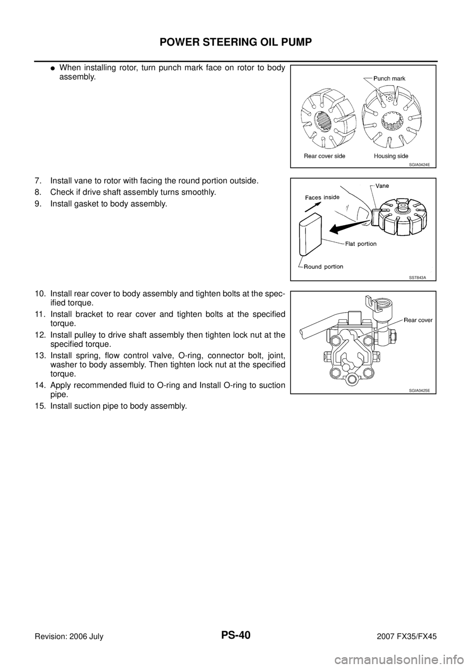
�When installing rotor, turn punch mark face on rotor to body
assembly.
7. Install vane to rotor with facing the round portion outside.
8. Check if drive shaft assembly turns smoothly.
9. Install gasket to body assembly.
10. Install rear cover to body assembly and tighten bolts at the spec- ified torque.
11. Install bracket to rear cover and tighten bolts at the specified torque.
12. Install pulley to drive shaft assembly then tighten lock nut at the specified torque.
13. Install spring, flow control valve, O-ring, connector bolt, joint, washer to body assembly. Then tighten lock nut at the specified
torque.
14. Apply recommended fluid to O-ring and Install O-ring to suction pipe.
15. Install suction pipe to body assembly.
SGIA0424E
SST843A
SGIA0425E
Page 3948 of 4366

RFD-18
REAR FINAL DRIVE ASSEMBLY
Revision: 2006 July 2007 FX35/FX45
Disassembly and AssemblyNDS000CX
COMPONENTS
1. Drive pinion lock nut 2. Companion flange 3. Front oil seal
4. Pinion front bearing 5. Gear carrier 6. Side oil seal
7. Side flange 8. Collapsible spacer 9. Pinion rear bearing
10. Pinion height adjusting washer 11. Drive pinion 12. Side bearing adjusting washer
13. Side bearing 14. Side gear thrust washer 15. Circular clip
16. Side gear 17. Lock pin 18. Pinion mate gear
19. Pinion mate thrust washer 20. Pinion mate shaft 21. Drive gear
22. Differential case 23. Bearing cap 24. Filler plug
25. Gasket 26. Rear cover 27. Drain plug
A: Oil seal lip
B: Screw hole
C: After tightening the bolts to the specified torque, tighten the bolts additionally by turning the bolts 31 to 36 degrees.
Refer to GI-11, "
Components" and the followings for the symbols in the figure.
: Apply multi-purpose grease.
: Apply gear oil.
: Apply anti-corrosion oil.
: Apply Genuine Silicone RTV or equivalent. Refer to
GI-48, "
Recommended Chemical Products and Sealants" .
: Apply Genuine High Strength Thread Locking Sealant or equivalent. Refer to
GI-48, "
Recommended Chemical Prod-
ucts and Sealants" .
PDIA0986E
 box, install rotor snap
ring to slot in pulley shaft.
CAUTION:
Be careful not to damage roto")