Page 3966 of 4366

RFD-36
REAR FINAL DRIVE ASSEMBLY
Revision: 2006 July 2007 FX35/FX45
16. Using the drift, drive side oil seals until it becomes flush with the
case end.
CAUTION:
�Do not reuse oil seal.
�When installing, do not incline oil seal.
�Apply multi-purpose grease onto oil seal lips, and gear
oil onto the circumference of oil seal.
17. Check and adjust drive gear runout, tooth contact, drive gear to drive pinion backlash, and total preload torque. Refer to RFD-
19, "Drive Gear Runout" , RFD-20, "Tooth Contact" , RFD-21,
"Backlash" , RFD-19, "Total Preload Torque" .
Recheck above items. Readjust the above description, if necessary.
18. Apply sealant to mating surface of rear cover.
�Use Genuine Silicone RTV or equivalent. Refer to GI-48,
"RECOMMENDED CHEMICAL PRODUCTS AND SEAL-
ANTS" .
CAUTION:
Remove old sealant adhering to mounting surfaces. Also
remove any moisture, oil, or foreign material adhering to
application and mounting surfaces.
19. Install rear cover on gear carrier and tighten mounting bolts with the specified torque. Refer to RFD-18, "
COMPONENTS" .
20. Install side flange with the following procedure.
a. Attach the protector to side oil seal.
b. After the side flange is inserted and the serrated part of side gear has engaged the serrated part of flange, remove the pro-
tector.
c. Put a suitable drift on the center of side flange, then drive it until sound changes.
NOTE:
When installation is completed, driving sound of the side flange
turns into a sound which seems to affect the whole final drive.
d. Confirm that the dimension of the side flange installation (Mea- surement A) in the figure comes into the following. Tool number : KV38100200 (J-26233)
SPD560
PDIA0961E
Tool number : KV38107900 (J-39352)
SDIA0822E
Measurement A: 326 - 328 mm (12.83 - 12.91 in)
SDIA1039E
Page 3973 of 4366

REAR SUSPENSION ASSEMBLY RSU-5
C
D
F
G H
I
J
K L
M A
B
RSU
Revision: 2006 July 2007 FX35/FX45
REAR SUSPENSION ASSEMBLYPFP:55020
On-Vehicle Inspection and ServiceNES000HU
Make sure the mounting conditions (looseness, back lash) of each component and component status (wear,
damage) are normal.
INSPECTION OF BALL JOINT END PLAY
Measure axial end play by installing and moving up/down with an
iron pry bar or something similar between suspension arm and axle.
CAUTION:
Be careful not to damage ball joint boot.
SHOCK ABSORBER INSPECTION
Check shock absorber for oil leakage, damage and replace if necessary.
Wheel Alignment InspectionNES000HV
DESCRIPTION
�Measure wheel alignment under unladen conditions. “Unladen conditions” means that fuel, engine cool-
ant, and lubricant are full. Spare tire, jack, hand tools and mats in designated positions.
PRELIMINARY INSPECTION
�Check tires for improper air pressure and wear.
�Check road wheels for runout.
�Check wheel bearing axial end play.
�Check ball joint axial end play of suspension arm.
�Check shock absorber operation.
�Check each mounting point of axle and suspension for looseness and deformation.
�Check each link, arm and member for cracks, deformation, and other damage.
�Check vehicle posture.
GENERAL INFORMATION AND RECOMMENDATIONS
�A four-wheel thrust alignment should be performed.
–This type of alignment is recommended for any NISSAN/INFINITI vehicle.
–The four-wheel “thrust” process helps ensure that the vehicle is properly aligned and the steering wheel is
centered.
–The alignment rack itself should be capable of accepting any NISSAN/INFINITI vehicle.
–The rack should be checked to ensure that it is level.
�Make sure the machine is properly calibrated.
–Your alignment equipment should be regularly calibrated in order to give correct information.
–Check with the manufacturer of your specific equipment for their recommended Service/Calibration
Schedule. Standard value
Axial end play : 0 mm (0 in)
SEIA0245J
Page 4260 of 4366
TF-56
TRANSFER ASSEMBLY
Revision: 2006 July 2007 FX35/FX45
16. Apply liquid gasket to mating surface of rear case.
�Use Genuine Anaerobic Liquid Gasket or equivalent.
Refer to GI-48, "
Recommended Chemical Products and
Sealants" .
CAUTION:
Remove old sealant adhering to mounting surfaces. Also
remove any moisture, oil, or foreign material adhering to
application and mounting surfaces.
17. Set front case to rear case. CAUTION:
Be careful not to damage the mating surface transmission
side.
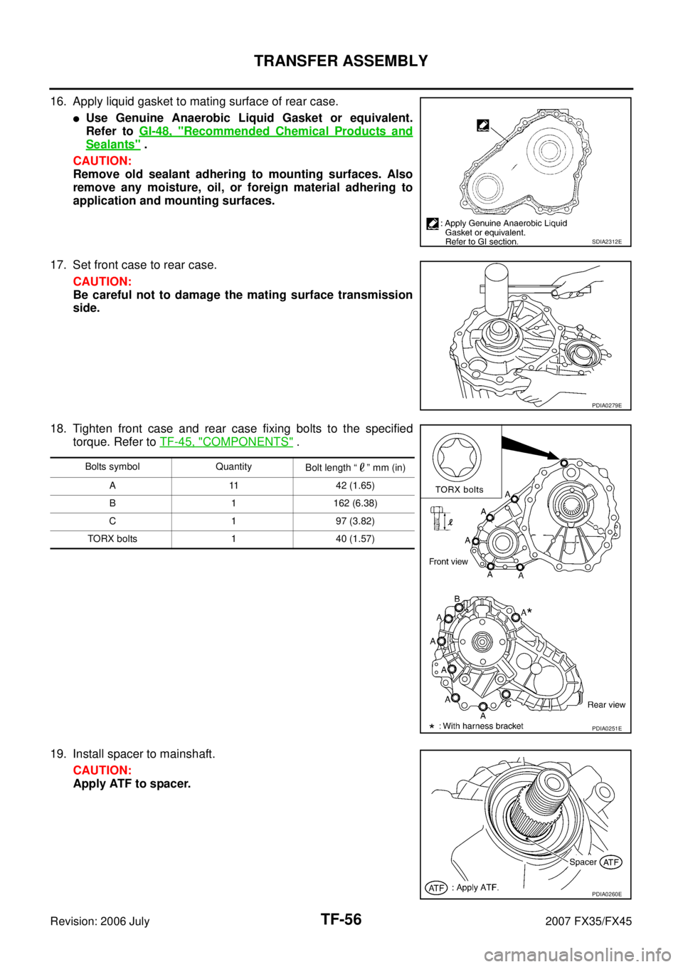
18. Tighten front case and rear case fixing bolts to the specified torque. Refer to TF-45, "
COMPONENTS" .
19. Install spacer to mainshaft. CAUTION:
Apply ATF to spacer.
SDIA2312E
PDIA0279E
Bolts symbol Quantity Bolt length “ ” mm (in)
A 11 42 (1.65)
B 1 162 (6.38)
C 1 97 (3.82)
TORX bolts 1 40 (1.57)
PDIA0251E
PDIA0260E
Page 4262 of 4366
TF-58
TRANSFER ASSEMBLY
Revision: 2006 July 2007 FX35/FX45
�Use Genuine Silicone RTV or equivalent. Refer to GI-48, "Recommended Chemical Products and
Sealants" .
CAUTION:
Remove old sealant and oil adhering to threads.
26. Set gasket to filler plug. Install it to rear case and tighten to the specified torque. Refer to TF-45, "
COM-
PONENTS" .
CAUTION:
Do not reuse gasket.