Page 4246 of 4366
TF-42
REAR OIL SEAL
Revision: 2006 July 2007 FX35/FX45
INSTALLATION
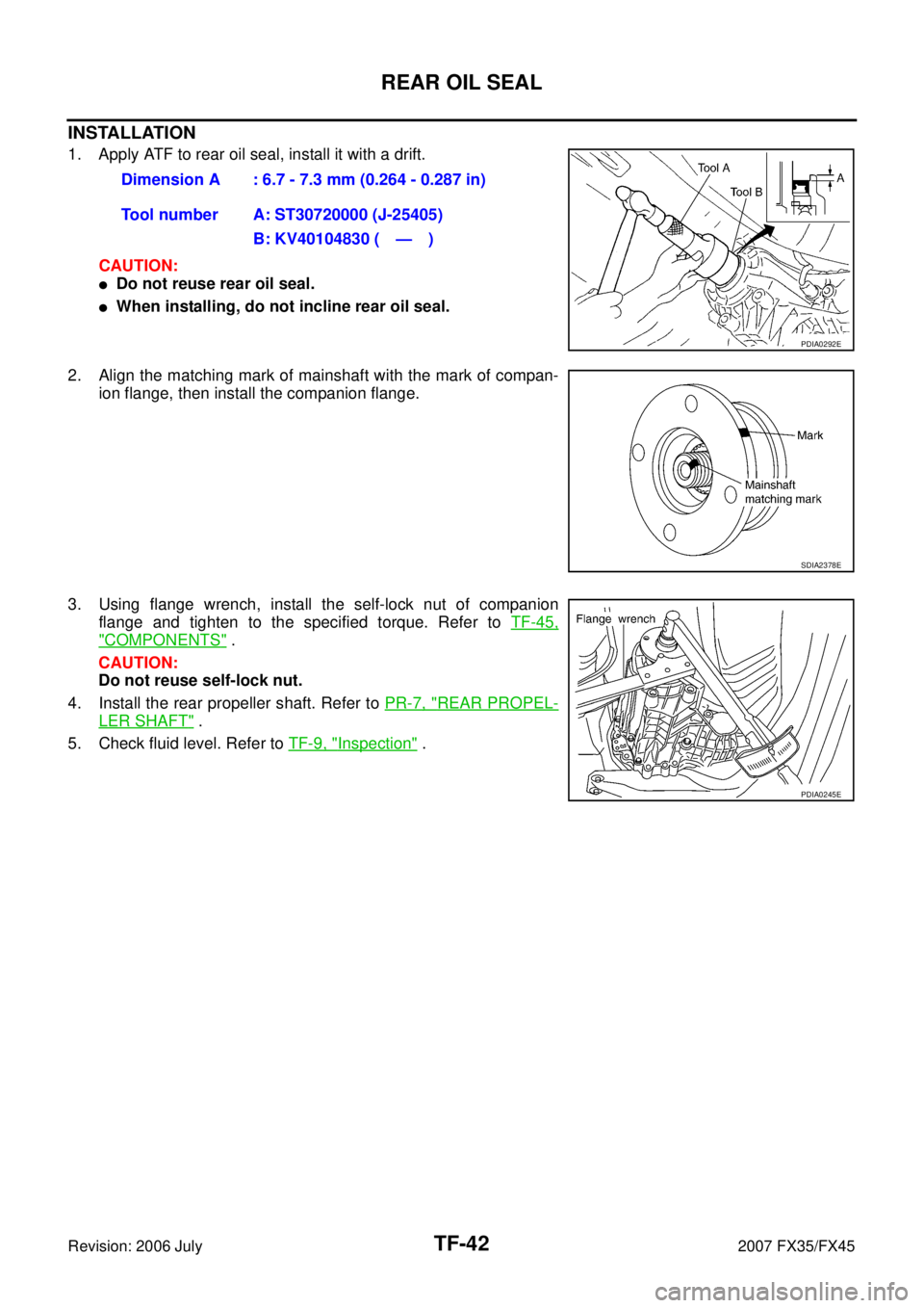
1. Apply ATF to rear oil seal, install it with a drift.
CAUTION:
�Do not reuse rear oil seal.
�When installing, do not incline rear oil seal.
2. Align the matching mark of mainshaft with the mark of compan- ion flange, then install the companion flange.
3. Using flange wrench, install the self-lock nut of companion flange and tighten to the specified torque. Refer to TF-45,
"COMPONENTS" .
CAUTION:
Do not reuse self-lock nut.
4. Install the rear propeller shaft. Refer to PR-7, "
REAR PROPEL-
LER SHAFT" .
5. Check fluid level. Refer to TF-9, "
Inspection" .
Dimension A : 6.7 - 7.3 mm (0.264 - 0.287 in)
Tool number A: ST30720000 (J-25405) B: KV40104830 ( — )
PDIA0292E
SDIA2378E
PDIA0245E
Page 4249 of 4366
TRANSFER ASSEMBLY TF-45
C E F
G H
I
J
K L
M A
B
TF
Revision: 2006 July 2007 FX35/FX45
Disassembly and AssemblyNDS000AO
COMPONENTS
1. Drive chain 2. Front drive shaft rear bearing 3. Front drive shaft
4. Front drive shaft front bearing 5. Sprocket 6. Mainshaft
7. Needle bearing 8. Snap ring 9. Mainshaft bearing
10. Front case 11. Front oil seal 12. Mainshaft oil seal
13. Oil cover 14. Temperature sensor 15. Electric controlled coupling
16. Spacer 17. Snap ring 18. O-ring
19. Oil gutter 20. Drain plug 21. Baffle plate
22. Rear bearing 23. Snap ring 24. Spacer
25. Rear oil seal 26. Companion flange 27. Self-lock nut
28. Breather tube 29. Rear case 30. Harness bracket
31. Retainer 32. Filler plug 33. Gasket
PDIA0244E
Page 4250 of 4366
TF-46
TRANSFER ASSEMBLY
Revision: 2006 July 2007 FX35/FX45
DISASSEMBLY
Front Case and Rear Case
1. Remove drain plug and filler plug.
2. Remove mainshaft oil seal from front case, using a flat-bladed screwdriver.
CAUTION:
Be careful not to damage the front case and mainshaft.
3. Remove front oil seal from front case, using a flat-bladed screw- driver.
CAUTION:
Be careful not to damage the front case and front drive
shaft.
4. Remove self-lock nut.
5. Put a matching mark on the end of mainshaft. The mark should be in line with the mark on the companion flange.
CAUTION:
For matching mark, use paint. Do not damage mainshaft.
6. Remove companion flange, using a puller. CAUTION:
Be careful not to damage the companion flange.
PDIA0253E
PDIA0255E
SDIA2378E
PDIA0258E
Page 4251 of 4366
TRANSFER ASSEMBLY TF-47
C E F
G H
I
J
K L
M A
B
TF
Revision: 2006 July 2007 FX35/FX45
7. Remove rear oil seal from rear case, using a puller.
CAUTION:
Be careful not to damage the rear case.
8. Remove spacer from mainshaft.
9. Remove front case and rear case fixing bolts, then remove har- ness bracket.
10. Separate front case and rear case. Then, remove front case by levering it up with a tire lever or the like.
CAUTION:
Be careful not to damage the mating surface. Tool number : KV381054S0 (J-34286)
PDIA0259E
PDIA0260E
Bolts symbol Quantity
Bolt length “ ” mm (in)
A 11 42 (1.65)
B 1 162 (6.38)
C 1 97 (3.82)
TORX bolts 1 40 (1.57)
PDIA0251E
SDIA2460E
Page 4252 of 4366
TF-48
TRANSFER ASSEMBLY
Revision: 2006 July 2007 FX35/FX45
11. Remove snap ring from front case.
12. Remove mainshaft bearing from front case, using a drift.
13. Remove drive chain and front drive shaft while tapping front drive shaft with plastic hammer.
CAUTION:
Be careful not to tap drive chain.
14. Remove oil gutter from rear case.
15. Remove oil cover bolt and sensor fixing bolt from rear case. And then, remove oil cover.
PDIA0267E
Tool number : KV38100300 (J-25523)
PDIA0256E
PDIA0257E
PDIA0261E
SDIA2403E
Page 4258 of 4366
TF-54
TRANSFER ASSEMBLY
Revision: 2006 July 2007 FX35/FX45
4. Install snap ring to rear case.
CAUTION:
Do not reuse snap ring.
5. Install mainshaft assembly to rear case, using a drift. CAUTION:
ATF should be applied to contact surface of mainshaft and
rear bearing.
6. Install O-ring to transfer assembly harness connector. CAUTION:
�Do not reuse O-ring.
�Apply ATF to O-ring.
7. Install transfer assembly harness connector into rear case.
8. Install retainer to transfer assembly harness connector.
9. Set temperature sensor and tighten bolt to the specified torque. Refer to TF-45, "
COMPONENTS" .
10. Hold electric controlled coupling harness with oil cover hold plate, install oil cover to rear case, and tighten bolt to the speci-
fied torque. Refer to TF-45, "
COMPONENTS" .
CAUTION:
The harness should be guided by a cut portion.
PDIA0263E
Tool number : ST35321000 ( — )
SDIA2368E
SDIA1597E
SDIA2404E
Page 4259 of 4366
TRANSFER ASSEMBLY TF-55
C E F
G H
I
J
K L
M A
B
TF
Revision: 2006 July 2007 FX35/FX45
11. Install oil gutter to rear case.
CAUTION:
The tip of oil gutter should be put into rear case groove.
12. Install drive chain to front drive shaft. CAUTION:
Identification mark of drive chain should be in the side of
front bearing of front drive shaft.
13. Install drive chain to mainshaft, and then install tap front drive shaft with plastic hammer. Press-fit rear bearing of front drive
shaft to rear case.
CAUTION:
Be careful not to tap drive chain.
14. Install mainshaft bearing to front case, using a drift.
15. Install snap ring to front case. CAUTION:
Do not reuse snap ring.
PDIA0261E
PDIA0284E
PDIA0257E
Tool number : ST30621000 (J-25742-5)
PDIA0283E
PDIA0267E
Page 4260 of 4366
TF-56
TRANSFER ASSEMBLY
Revision: 2006 July 2007 FX35/FX45
16. Apply liquid gasket to mating surface of rear case.
�Use Genuine Anaerobic Liquid Gasket or equivalent.
Refer to GI-48, "
Recommended Chemical Products and
Sealants" .
CAUTION:
Remove old sealant adhering to mounting surfaces. Also
remove any moisture, oil, or foreign material adhering to
application and mounting surfaces.
17. Set front case to rear case. CAUTION:
Be careful not to damage the mating surface transmission
side.
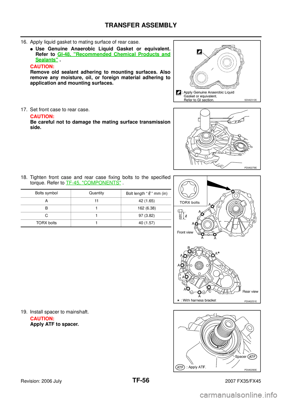
18. Tighten front case and rear case fixing bolts to the specified torque. Refer to TF-45, "
COMPONENTS" .
19. Install spacer to mainshaft. CAUTION:
Apply ATF to spacer.
SDIA2312E
PDIA0279E
Bolts symbol Quantity Bolt length “ ” mm (in)
A 11 42 (1.65)
B 1 162 (6.38)
C 1 97 (3.82)
TORX bolts 1 40 (1.57)
PDIA0251E
PDIA0260E