Page 4189 of 4366

DRIVER AIR BAG MODULE SRS-43
C
D E
F
G
I
J
K L
M A
B
SRS
Revision: 2006 July 2007 FX35/FX45
CAUTION:
�Always place driver air bag module with pad side facing
upward.
�Do not insert any foreign objects (screwdriver, etc.) into
driver air bag module.
�Do not disassemble driver air bag module.
�Do not use old bolts after removal; replace with new bolts.
�Do not expose the driver air bag module to temperatures
exceeding 90 °C (194 °F).
�Replace driver air bag module if it has been dropped or sus-
tained an impact.
�Do not allow oil, grease or water to come in contact with the
driver air bag module.
INSTALLATION
Install in the reverse order of removal.
CAUTION:
�Fix the air bag module harness (shown as A in the figure) to
the harness fixing hook (shown as B in the figure).
�Be careful not to damage the harness while installing.
�Tighten the special bolts after exactly adjusting the centers of fixing holes on the air bag module
side and the steering wheel side. If the holes are misaligned, the bolt threads are damaged and the
module is not installed securely.
�After the work is completed, make sure no system malfunction is detected by air bag warning
lamp.
�In case that malfunction is detected by the air bag warning lamp, reset by the self-diagnosis func-
tion and delete the memory by CONSOULT–II.
�In case that malunction is still detected after the above operation, peform self-diagnosis to repair
malfunctions. Refer to Refer to SRS-20, "
SRS Operation Check" .
PHIA0320E
SBF814E
PHIA0885J
Page 4193 of 4366

FRONT PASSENGER AIR BAG MODULE SRS-47
C
D E
F
G
I
J
K L
M A
B
SRS
Revision: 2006 July 2007 FX35/FX45
�Replace front passenger air bag module if it has been
dropped or sustained an impact.
�Do not expose the front passenger air bag module to tem-
peratures exceeding 90 °C (194 °F).
�Do not allow oil, grease or water to come in contact with the
front passenger air bag module.
�After front passenger air bag module inflates, the instru-
ment panel assembly should be replaced.
INSTALLATION
Install in the reverse order of removal.
CAUTION:
�Be careful not to damage the harness while installing.
�After the work is completed, make sure no system malfunction is detected by air bag warning
lamp.
�In case that malfunction is detected by the air bag warning lamp, reset by the self-diagnosis func-
tion and delete the memory by CONSULT −II.
�In case that malfunction is still detected after the above operation, perform self-diagnosis to repair
malfunctions. Refer to Refer to SRS-20, "
SRS Operation Check" .
SBF814E
Page 4195 of 4366
SIDE CURTAIN AIR BAG MODULE SRS-49
C
D E
F
G
I
J
K L
M A
B
SRS
Revision: 2006 July 2007 FX35/FX45
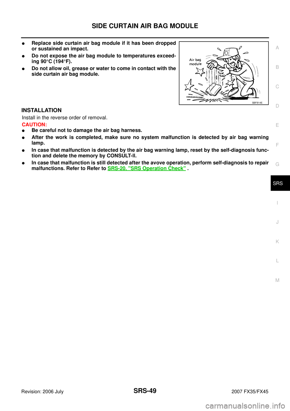
�Replace side curtain air bag module if it has been dropped
or sustained an impact.
�Do not expose the air bag module to temperatures exceed-
ing 90 °C (194 °F).
�Do not allow oil, grease or water to come in contact with the
side curtain air bag module.
INSTALLATION
Install in the reverse order of removal.
CAUTION:
�Be careful not to damage the air bag harness.
�After the work is completed, make sure no system malfunction is detected by air bag warning
lamp.
�In case that malfunction is detected by the air bag warning lamp, reset by the self-diagnosis func-
tion and delete the memory by CONSULT-ll.
�In case that malfunction is still detected after the avove operation, perform self-diagnosis to repair
malfunctions. Refer to Refer to SRS-20, "
SRS Operation Check" .
SBF814E
Page 4206 of 4366

TF-2Revision: 2006 July 2007 FX35/FX45
Started .................................................................
... 35
DIAGNOSTIC PROCEDURE ........................... ... 35
Vehicle Does Not Enter AWD Mode Even Though
AWD Warning Lamp Turned to OFF .................... ... 36
DIAGNOSTIC PROCEDURE ........................... ... 36
While Driving, AWD Warning Lamp Flashes Rapidly
(When Flashing in Approx. 1 Minute and Then Turn-
ing OFF) .............................................................. ... 37
While Driving, AWD Warning Lamp Flashes Slowly
(When Continuing to Flash until Turning Ignition
Switch OFF) ......................................................... ... 37
DIAGNOSTIC PROCEDURE ........................... ... 37
AWD CONTROL UNIT ........................................... ... 39
Removal and Installation ..................................... ... 39
REMOVAL ........................................................ ... 39
INSTALLATION ................................................. ... 39
FRONT OIL SEAL .................................................. ... 40
Removal and Installation ..................................... ... 40
REMOVAL ........................................................ ... 40
INSTALLATION ................................................. ... 40 REAR OIL SEAL ....................................................
... 41
Removal and Installation ...................................... ... 41
REMOVAL ......................................................... ... 41
INSTALLATION ................................................. ... 42
AIR BREATHER HOSE .......................................... ... 43
Removal and Installation ...................................... ... 43
TRANSFER ASSEMBLY ........................................ ... 44
Removal and Installation ...................................... ... 44
REMOVAL ......................................................... ... 44
INSTALLATION ................................................. ... 44
Disassembly and Assembly ................................. ... 45
COMPONENTS ................................................ ... 45
DISASSEMBLY ................................................. ... 46
INSPECTION .................................................... ... 51
ASSEMBLY ....................................................... ... 52
SERVICE DATA AND SPECIFICATIONS (SDS) ... ... 59
General Specifications ......................................... ... 59
Page 4209 of 4366

PREPARATION TF-5
C E F
G H
I
J
K L
M A
B
TF
Revision: 2006 July 2007 FX35/FX45
PREPARATIONPFP:00002
Special Service ToolsNDS0009P
The actual shapes of Kent-Moore tools may differ from those of special service tools illustrated here.
Tool number
(Kent-Moore No.)
Tool name Description
ST27862000
(—)
Drift
a: 62.5 mm (2.461 in) dia.
b: 42 mm (1.65 in) dia.
�Installing front oil seal
KV381054S0
(J-34286)
Puller
�Removing rear oil seal
ST30720000
(J-25405)
Drift
a: 77 mm (3.03 in) dia.
b: 55.5 mm (2.185 in) dia.
�Installing rear oil seal
�Installing mainshaft oil seal
KV40104830
(—)
Drift
a: 70 mm (2.76 in) dia.
b: 63.5 mm (2.500 in) dia.
�Installing rear oil seal
KV38100300
(J-25523)
Drift
a: 54 mm (2.13 in) dia.
b: 46 mm (1.81 in) dia.
c: 32 mm (1.26 in) dia.
�Removing mainshaft bearing
ST33052000
(—)
Drift
a: 28 mm (1.10 in) dia.
b: 22 mm (0.87 in) dia.
�Removing mainshaft assembly
ST30611000
(J-25742-1)
Drift bar
a: 350 mm (1.10 in)
b: 25 mm (1.10 in) dia.
c: M12 × 1.5P
�Removing rear bearing
ZZA0194D
ZZA0601D
ZZA0811D
ZZA1003D
ZZA1046D
ZZA1000D
NT663
Page 4212 of 4366
TF-8
NOISE, VIBRATION AND HARSHNESS (NVH) TROUBLESHOOTING
Revision: 2006 July 2007 FX35/FX45
NOISE, VIBRATION AND HARSHNESS (NVH) TROUBLESHOOTINGPFP:00003
NVH Troubleshooting ChartNDS0009R
Use the chart below to help you find the cause of the symptom. The numbers indicate the order of the inspec-
tion. If necessary, repair or replace these parts.
Reference pageTF-9TF-45TF-45TF-51TF-51TF-51
SUSPECTED PARTS
(Possible cause)
TRANSFER FLUID (Level low)
TRANSFER FLUID (Wrong)
TRANSFER FLUID (Level too high)
LIQUID GASKET (Damaged)
OIL SEAL (Worn or damaged)
GEAR (Worn or damaged)
BEARING (Worn or damaged)
TRANSFER CASE (Damaged)
Symptom Noise 1 2 3 3 3
Transfer fluid leakage 4 1 2 2 3
Page 4244 of 4366
TF-40
FRONT OIL SEAL
Revision: 2006 July 2007 FX35/FX45
FRONT OIL SEALPFP:38189
Removal and InstallationNDS000AK
REMOVAL
1. Remove the drain plug to drain the transfer fluid. Refer to TF-9, "Replacement" .
2. Remove the front propeller shaft. Refer to PR-4, "
FRONT PROPELLER SHAFT" .
3. Remove front oil seal using a flat-bladed screwdriver. CAUTION:
Be careful not to damage the front case and front drive
shaft.
INSTALLATION
1. Apply ATF to front oil seal, install it with a drift until the end face of front case.
CAUTION:
�Do not reuse front oil seal.
�When installing, do not incline front oil seal.
2. Install front propeller shaft. Refer to PR-4, "
FRONT PROPEL-
LER SHAFT" .
3. Install transfer fluid, check fluid level and for fluid leakage. Refer to TF-9, "
Inspection" .
SDIA1782E
Tool number : ST27862000 ( — )
SDIA1783E
Page 4245 of 4366
REAR OIL SEAL TF-41
C E F
G H
I
J
K L
M A
B
TF
Revision: 2006 July 2007 FX35/FX45
REAR OIL SEALPFP:33140
Removal and InstallationNDS000AL
REMOVAL
1. Remove the rear propeller shaft. Refer to PR-7, "REAR PROPELLER SHAFT" .
2. Remove self-lock nut of companion flange using the flange wrench.
3. Put matching mark on the end of the mainshaft. The mark should be in line with the mark on the companion flange.
CAUTION:
For matching mark, use paint. Do not damage mainshaft.
4. Remove the companion flange using a puller. CAUTION:
Be careful not to damage the companion flange.
5. Remove the rear oil seal using a puller. CAUTION:
Be careful not to damage the rear case.
SDIA2454E
SDIA2378E
SDIA1785E
Tool number : KV381054S0 (J-34286)
SDIA1786E
 TROUBLESHOOTING
Revision: 2006 July 2007 FX35/FX45
NOISE, VIBRATION AND HARSHNESS (NVH) TROUBLESHOOTINGPFP:00003
NVH Troubleshooting ChartNDS0009R
Use the cha")

