Page 187 of 4366

TROUBLE DIAGNOSIS AT-103
D E
F
G H
I
J
K L
M A
B
AT
Revision: 2006 July 2007 FX35/FX45
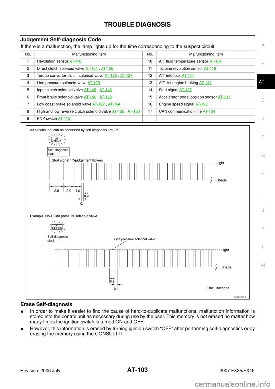
Judgement Self-diagnosis Code
If there is a malfunction, the lamp lights up for the time corresponding to the suspect circuit.
Erase Self-diagnosis
�In order to make it easier to find the cause of hard-to-duplicate malfunctions, malfunction information is
stored into the control unit as necessary during use by the user. This memory is not erased no matter how
many times the ignition switch is turned ON and OFF.
�However, this information is erased by turning ignition switch “OFF” after performing self-diagnostics or by
erasing the memory using the CONSULT-II.
No. Malfunctioning item No. Malfunctioning item
1 Revolution sensor AT- 11 8
10 A/T fluid temperature sensor AT- 1 3 4
2 Direct clutch solenoid valve AT-154 , AT-15611 Turbine revolution sensor AT- 11 6
3 Torque converter clutch solenoid valve AT-125 , AT- 1 2 712 A/T interlock AT- 1 4 1
4 Line pressure solenoid valve AT-12913 A/T 1st engine braking AT-144
5 Input clutch solenoid valve AT- 1 4 6 , AT- 1 4 814 Start signal AT-107
6 Front brake solenoid valve AT- 1 5 0 , AT- 1 5 215 Accelerator pedal position sensor AT- 1 3 1
7 Low coast brake solenoid valve AT- 1 6 2 , AT- 1 6 416 Engine speed signal AT- 1 2 3
8 High and low reverse clutch solenoid valve AT- 1 5 8 , AT- 1 6 017 CAN communication line AT- 1 0 4
9 PNP switch AT- 11 2
SCIA5767E
Page 229 of 4366

DTC P1731 A/T 1ST ENGINE BRAKING AT-145
D E
F
G H
I
J
K L
M A
B
AT
Revision: 2006 July 2007 FX35/FX45
Diagnostic ProcedureNCS001EO
1. CHECK INPUT SIGNALS
With CONSULT-II
1. Start the engine.
2. Select “SELECTION FROM MENU” in “DATA MONITOR” mode for “A/T” with CONSULT-II.
3. Drive vehicle in the “M” position (1st gear), and confirm the ON/ OFF actuation of “ATF PRES SW 2” and “ON OFF SOL”.
OK or NG
OK >> GO TO 4.
NG >> GO TO 2.
2. CHECK TCM POWER SUPPLY AND GROUND CIRCUIT
Check TCM power supply and ground circuit. Refer to AT- 1 7 9 , "
MAIN POWER SUPPLY AND GROUND CIR-
CUIT" .
OK or NG
OK >> GO TO 3.
NG >> Repair or replace damaged parts.
3. DETECT MALFUNCTIONING ITEM
Check A/T assembly harness connector pin terminals for damage or loose connection with harness connector.
OK or NG
OK >> Replace the control valve with TCM. Refer to AT- 2 3 9 , "Control Valve with TCM and A/T Fluid Tem-
perature Sensor 2" .
NG >> Repair or replace damaged parts.
4. CHECK DTC
Perform AT- 1 4 4 , "
DTC Confirmation Procedure" .
OK or NG
OK >> INSPECTION END
NG >> GO TO 2.
Item name Condition Display value
ON OFF SOL Low coast brake engaged. Refer to
AT- 2 2
.ON
Low coast brake disengaged. Refer to AT- 2 2
.OFF
ATF PRES
SW 2 Low coast brake engaged. Refer to
AT- 2 2
.ON
Low coast brake disengaged. Refer to AT- 2 2
.OFF
SCIA4670E
Page 235 of 4366

DTC P1757 FRONT BRAKE SOLENOID VALVE AT-151
D E
F
G H
I
J
K L
M A
B
AT
Revision: 2006 July 2007 FX35/FX45
Diagnostic ProcedureNCS001F6
1. CHECK INPUT SIGNAL
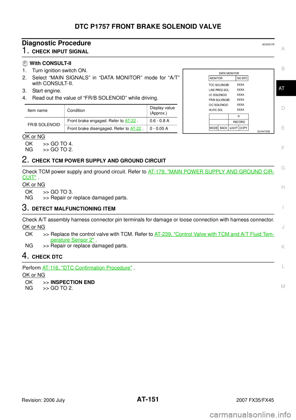
With CONSULT-II
1. Turn ignition switch ON.
2. Select “MAIN SIGNALS” in “DATA MONITOR” mode for “A/T” with CONSULT-II.
3. Start engine.
4. Read out the value of “FR/B SOLENOID” while driving.
OK or NG
OK >> GO TO 4.
NG >> GO TO 2.
2. CHECK TCM POWER SUPPLY AND GROUND CIRCUIT
Check TCM power supply and ground circuit. Refer to AT- 1 7 9 , "
MAIN POWER SUPPLY AND GROUND CIR-
CUIT" .
OK or NG
OK >> GO TO 3.
NG >> Repair or replace damaged parts.
3. DETECT MALFUNCTIONING ITEM
Check A/T assembly harness connector pin terminals for damage or loose connection with harness connector.
OK or NG
OK >> Replace the control valve with TCM. Refer to AT- 2 3 9 , "Control Valve with TCM and A/T Fluid Tem-
perature Sensor 2" .
NG >> Repair or replace damaged parts.
4. CHECK DTC
Perform AT- 11 6 , "
DTC Confirmation Procedure" .
OK or NG
OK >> INSPECTION END
NG >> GO TO 2.
Item name Condition Display value
(Approx.)
FR/B SOLENOID Front brake engaged. Refer to
AT- 2 2
. 0.6 - 0.8 A
Front brake disengaged. Refer to AT- 2 2
. 0 - 0.05 ASCIA4793E
Page 237 of 4366

DTC P1759 FRONT BRAKE SOLENOID VALVE FUNCTION AT-153
D E
F
G H
I
J
K L
M A
B
AT
Revision: 2006 July 2007 FX35/FX45
WITH GST
Follow the procedure “WITH CONSULT-II”.
Diagnostic ProcedureNCS001FC
1. CHECK INPUT SIGNALS
With CONSULT-II
1. Start engine.
2. Select “SELECTION FROM MENU” in “DATA MONITOR” mode for “A/T” with CONSULT-II.
3. Drive vehicle in the “D” position (3rd � 4th gear), and confirm
the ON/OFF actuation of the “ATF PRES SW 1” and electrical
current value of “FR/B SOLENOID”.
OK or NG
OK >> GO TO 4.
NG >> GO TO 2.
2. CHECK TCM POWER SUPPLY AND GROUND CIRCUIT
Check TCM power supply and ground circuit. Refer to AT- 1 7 9 , "
MAIN POWER SUPPLY AND GROUND CIR-
CUIT" .
OK or NG
OK >> GO TO 3.
NG >> Repair or replace damaged parts.
3. DETECT MALFUNCTIONING ITEM
Check A/T assembly harness connector pin terminals for damage or loose connection with harness connector
OK or NG
OK >> Replace the control valve with TCM. Refer to AT- 2 3 9 , "Control Valve with TCM and A/T Fluid Tem-
perature Sensor 2" .
NG >> Repair or replace damaged parts.
4. CHECK DTC
Perform AT- 1 5 2 , "
DTC Confirmation Procedure" .
OK or NG
OK >> INSPECTION END
NG >> GO TO 2.
Item name Condition Display value
(Approx.)
FR/B SOLENOID Front brake engaged. Refer to
AT- 2 2
. 0.6 - 0.8 A
Front brake disengaged. Refer to AT- 2 2
. 0 - 0.05 A
ATF PRES SW 1 Front brake engaged. Refer to
AT- 2 2
.ON
Front brake disengaged. Refer to AT- 2 2
.OFF
SCIA4796E
Page 247 of 4366

DTC P1772 LOW COAST BRAKE SOLENOID VALVE AT-163
D E
F
G H
I
J
K L
M A
B
AT
Revision: 2006 July 2007 FX35/FX45
Diagnostic ProcedureNCS001G6
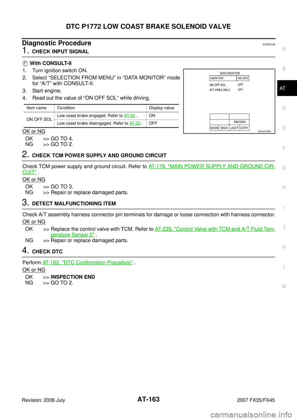
1. CHECK INPUT SIGNAL
With CONSULT-II
1. Turn ignition switch ON.
2. Select “SELECTION FROM MENU” in “DATA MONITOR” mode for “A/T” with CONSULT-II.
3. Start engine.
4. Read out the value of “ON OFF SOL” while driving.
OK or NG
OK >> GO TO 4.
NG >> GO TO 2.
2. CHECK TCM POWER SUPPLY AND GROUND CIRCUIT
Check TCM power supply and ground circuit. Refer to AT- 1 7 9 , "
MAIN POWER SUPPLY AND GROUND CIR-
CUIT" .
OK or NG
OK >> GO TO 3.
NG >> Repair or replace damaged parts.
3. DETECT MALFUNCTIONING ITEM
Check A/T assembly harness connector pin terminals for damage or loose connection with harness connector.
OK or NG
OK >> Replace the control valve with TCM. Refer to AT- 2 3 9 , "Control Valve with TCM and A/T Fluid Tem-
perature Sensor 2" .
NG >> Repair or replace damaged parts.
4. CHECK DTC
Perform AT- 1 6 2 , "
DTC Confirmation Procedure" .
OK or NG
OK >> INSPECTION END
NG >> GO TO 2.
Item name Condition Display value
ON OFF SOL Low coast brake engaged. Refer to
AT- 2 2
.ON
Low coast brake disengaged. Refer to AT- 2 2
.OFF
SCIA4794E
Page 249 of 4366

DTC P1774 LOW COAST BRAKE SOLENOID VALVE FUNCTION AT-165
D E
F
G H
I
J
K L
M A
B
AT
Revision: 2006 July 2007 FX35/FX45
Diagnostic ProcedureNCS001GC
1. CHECK INPUT SIGNALS
With CONSULT-II
1. Start engine.
2. Select “SELECTION FROM MENU” in “DATA MONITOR” mode for “A/T” with CONSULT-II.
3. Drive vehicle in the manual mode (1st or 2nd gear), and confirm the ON/OFF actuation of the “ATF PRES SW 2” and “ON OFF
SOL”.
OK or NG
OK >> GO TO 4.
NG >> GO TO 2.
2. CHECK TCM POWER SUPPLY AND GROUND CIRCUIT
Check TCM power supply and ground circuit. Refer to AT- 1 7 9 , "
MAIN POWER SUPPLY AND GROUND CIR-
CUIT" .
OK or NG
OK >> GO TO 3.
NG >> Repair or replace damaged parts.
3. DETECT MALFUNCTIONING ITEM
Check A/T assembly harness connector pin terminals for damage or loose connection with harness connector.
OK or NG
OK >> Replace the control valve with TCM. Refer to AT- 2 3 9 , "Control Valve with TCM and A/T Fluid Tem-
perature Sensor 2" .
NG >> Repair or replace damaged parts.
4. CHECK DTC
Perform AT- 1 6 4 , "
DTC Confirmation Procedure" .
OK or NG
OK >> INSPECTION END
NG >> GO TO 2.
Item name Condition Display value
ON OFF SOL Low coast brake engaged. Refer to
AT- 2 2
.ON
Low coast brake disengaged. Refer to AT- 2 2
.OFF
ATF PRES SW 2 Low coast brake engaged. Refer to
AT- 2 2
.ON
Low coast brake disengaged. Refer to AT- 2 2
.OFF
SCIA4794E
Page 256 of 4366

AT-172
DTC P1841 ATF PRESSURE SWITCH 1
Revision: 2006 July 2007 FX35/FX45
Diagnostic ProcedureNCS001GQ
1. CHECK INPUT SIGNAL
With CONSULT-II
1. Start engine.
2. Select “ECU INPUT SIGNALS” or “MAIN SIGNALS” in “DATA MONITOR” mode for “A/T” with CONSULT-II.
3. Drive vehicle in the “D” position (3rd � 4th gear), and confirm
the ON/OFF actuation of the “ATF PRES SW 1”.
OK or NG
OK >> GO TO 4.
NG >> GO TO 2.
2. CHECK TCM POWER SUPPLY AND GROUND CIRCUIT
Check TCM power supply and ground circuit. Refer to AT- 1 7 9 , "
MAIN POWER SUPPLY AND GROUND CIR-
CUIT" .
OK or NG
OK >> GO TO 3.
NG >> Repair or replace damaged parts.
3. DETECT MALFUNCTIONING ITEM
Check A/T assembly harness connector pin terminals for damage or loose connection with harness connector.
OK or NG
OK >> Replace the control valve with TCM. Refer to AT- 2 3 9 , "Control Valve with TCM and A/T Fluid Tem-
perature Sensor 2" .
NG >> Repair or replace damaged parts.
4. CHECK DTC
Perform AT- 1 7 1 , "
DTC Confirmation Procedure" .
OK or NG
OK >> INSPECTION END
NG >> GO TO 2.
Item name Condition Display value
ATF PRES SW 1 Front brake engaged. Refer to
AT- 2 2
.ON
Front brake disengaged. Refer to AT- 2 2
.OFF
PCIA0067E
Page 281 of 4366

TROUBLE DIAGNOSIS FOR SYMPTOMS AT-197
D E
F
G H
I
J
K L
M A
B
AT
Revision: 2006 July 2007 FX35/FX45
5. DETECT MALFUNCTIONING ITEM
1. Disassemble A/T. Refer to AT- 2 9 4 , "
DISASSEMBLY" .
2. Check the following.
–Reverse brake. Refer to AT- 2 9 4 , "DISASSEMBLY" .
OK or NG
OK >> GO TO 9.
NG >> Repair or replace damaged parts.
6. CHECK LINE PRESSURE
Check the line pressure with the engine idling. Refer to AT- 5 4 , "
LINE
PRESSURE TEST" .
OK or NG
OK >> GO TO 9.
NG-1 >> Line pressure high: GO TO 7.
NG-2 >> Line pressure low: GO TO 8.
7. DETECT MALFUNCTIONING ITEM
1. Check control valve with TCM. Refer to AT- 2 3 9 , "
Control Valve with TCM and A/T Fluid Temperature Sen-
sor 2" .
2. Disassemble A/T. Refer to AT- 2 9 4 , "
DISASSEMBLY" .
3. Check the following.
–Oil pump assembly. Refer to AT- 3 1 2 , "Oil Pump" .
OK or NG
OK >> GO TO 9.
NG >> Repair or replace damaged parts.
8. DETECT MALFUNCTIONING ITEM
1. Check control valve with TCM. Refer to AT- 2 3 9 , "
Control Valve with TCM and A/T Fluid Temperature Sen-
sor 2" .
2. Disassemble A/T. Refer to AT- 2 9 4 , "
DISASSEMBLY" .
3. Check the following.
–Oil pump assembly. Refer to AT- 3 1 2 , "Oil Pump" .
–Power train system. Refer to AT- 2 9 4 , "DISASSEMBLY" .
–Transmission case. Refer to AT- 2 9 4 , "DISASSEMBLY" .
OK or NG
OK >> GO TO 9.
NG >> Repair or replace damaged parts.
SAT494G