Page 1348 of 4366

DI-102
LANE DEPARTURE WARNING SYSTEM
Revision: 2006 July 2007 FX35/FX45
9. CHECK LDW SYSTEM ON INDICATOR
1. Connect LDW switch connector.
2. Turn ignition switch ON.
3. Apply ground to LDW switch terminal 2.
4. Check condition of the LDW system ON indicator.
OK or NG
OK >> Replace LDW camera unit.
NG >> Replace LDW switch.
LDW Indicator Lamp Circuit InspectionNKS0031M
1. CHECK OPERATION OF LDW INDICATOR LAMP
Check LDW indicator operation “INDICATOR LAMP DRIVE” in
“ACTIVE TEST” mode with CONSULT-II.
OK or NG
OK >> INSPECTION END
NG >> GO TO 2.
2. CHECK LDW INDICATOR LAMP SIGNAL CIRCUIT
1. Turn ignition switch OFF.
2. Disconnect LDW camera unit connector and combination meter connector.
3. Check continuity between LDW camera unit harness connector R9 terminal 8 and combination meter harness connector M20
terminal 17.
4. Check continuity between LDW camera unit harness connector R9 terminal 8 and ground.
OK or NG
OK >> GO TO 3.
NG >> Repair harness or connector. 2 – Ground : LDW system ON indicator
should illuminate.
PKIB4707E
“INDICATOR LAMP DRIVE”
Touch “ON” : LDW indicator lamp illuminates.
Touch “OFF” : LDW indicator lamp OFF.
PKIB4692E
8 – 17 : Continuity should exist.
8 – Ground : Continuity should not exist.
PKIB4708E
Page 1349 of 4366
LANE DEPARTURE WARNING SYSTEM DI-103
C
D E
F
G H
I
J
L
M A
B
DI
Revision: 2006 July 2007 FX35/FX45
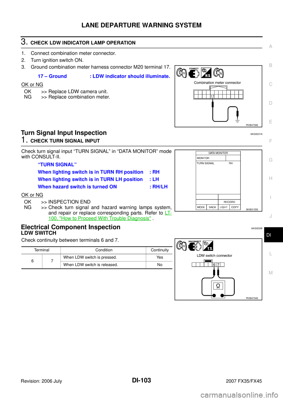
3. CHECK LDW INDICATOR LAMP OPERATION
1. Connect combination meter connector.
2. Turn ignition switch ON.
3. Ground combination meter harness connector M20 terminal 17.
OK or NG
OK >> Replace LDW camera unit.
NG >> Replace combination meter.
Turn Signal Input InspectionNKS0031N
1. CHECK TURN SIGNAL INPUT
Check turn signal input “TURN SIGNAL” in “DATA MONITOR” mode
with CONSULT-II.
OK or NG
OK >> INSPECTION END
NG >> Check turn signal and hazard warning lamps system,
and repair or replace corresponding parts. Refer to LT-
100, "How to Proceed With Trouble Diagnosis" .
Electrical Component InspectionNKS003IB
LDW SWITCH
Check continuity between terminals 6 and 7. 17 – Ground : LDW indicator should illuminate.
PKIB4709E
“TURN SIGNAL”
When lighting switch is in TURN RH position : RH
When lighting switch is in TURN LH position : LH
When hazard switch is turned ON : RH/LH
SKIB3125E
Terminal Condition Continuity
67 When LDW switch is pressed. Yes
When LDW switch is released. No
PKIB4704E
Page 1359 of 4366
REAR VIEW MONITOR DI-113
C
D E
F
G H
I
J
L
M A
B
DI
Revision: 2006 July 2007 FX35/FX45
REAR VIEW MONITORPFP:28260
System DescriptionNKS0031T
�The rear view monitor is equipped to check the rearward of the vehicle with display when A/T selector
lever is in reverse position.
�The lines of vehicle sides and the distance from the rear end of the vehicle are provided on display as a
guide. It allows the driver to know the distance between the vehicle and a rearward object, and the width
of the vehicle much easier.
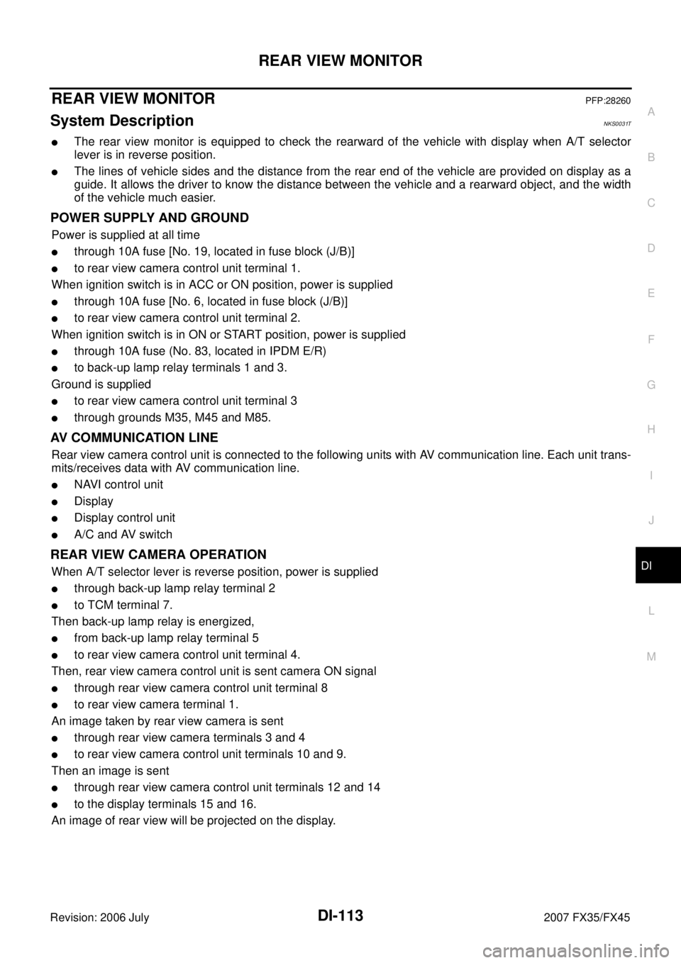
POWER SUPPLY AND GROUND
Power is supplied at all time
�through 10A fuse [No. 19, located in fuse block (J/B)]
�to rear view camera control unit terminal 1.
When ignition switch is in ACC or ON position, power is supplied
�through 10A fuse [No. 6, located in fuse block (J/B)]
�to rear view camera control unit terminal 2.
When ignition switch is in ON or START position, power is supplied
�through 10A fuse (No. 83, located in IPDM E/R)
�to back-up lamp relay terminals 1 and 3.
Ground is supplied
�to rear view camera control unit terminal 3
�through grounds M35, M45 and M85.
AV COMMUNICATION LINE
Rear view camera control unit is connected to the following units with AV communication line. Each unit trans-
mits/receives data with AV communication line.
�NAVI control unit
�Display
�Display control unit
�A/C and AV switch
REAR VIEW CAMERA OPERATION
When A/T selector lever is reverse position, power is supplied
�through back-up lamp relay terminal 2
�to TCM terminal 7.
Then back-up lamp relay is energized,
�from back-up lamp relay terminal 5
�to rear view camera control unit terminal 4.
Then, rear view camera control unit is sent camera ON signal
�through rear view camera control unit terminal 8
�to rear view camera terminal 1.
An image taken by rear view camera is sent
�through rear view camera terminals 3 and 4
�to rear view camera control unit terminals 10 and 9.
Then an image is sent
�through rear view camera control unit terminals 12 and 14
�to the display terminals 15 and 16.
An image of rear view will be projected on the display.
Page 1365 of 4366
REAR VIEW MONITOR DI-119
C
D E
F
G H
I
J
L
M A
B
DI
Revision: 2006 July 2007 FX35/FX45
Terminals and Reference Value for Rear View Camera Control UnitNKS0031X
Te r m i n a l s
Item Condition
Reference value
Terminal
No. Wire
color Ignition
switch Operation
1 R/W Battery power supply OFF — Battery voltage
2 LG Ignition power supply ACC — Battery voltage
3 B Ground ON — Approx. 0 V
4 OR Reverse signal input ON A/T selector lever R range
position Battery voltage
A/T selector lever in other than
R range position Approx. 0 V
5 G/Y CONTROL 1 ON — Approx. 0 V
6 PU DDL — — —
8 R/W Camera power output ON A/T selector lever R range
position Approx. 6 V
9 — Camera image input (–) ON — Approx. 0 V
10 W Camera image input (+) ON A/T selector lever R range
position
11 — Shield ground — — —
12 L Composite image output ON A/T selector lever R range
position
14 R Composite image synchroni-
zation signal output ON A/T selector lever R range
position
SKIA4894E
SKIA4896E
SKIA5896E
Page 1367 of 4366
REAR VIEW MONITOR DI-121
C
D E
F
G H
I
J
L
M A
B
DI
Revision: 2006 July 2007 FX35/FX45
Side Distance Guideline CorrectionNKS0031Z
This mode is used to modify the side distance guidelines if they are dislocated from the rear view monitor
image, because of variations of body/camera mounting conditions.
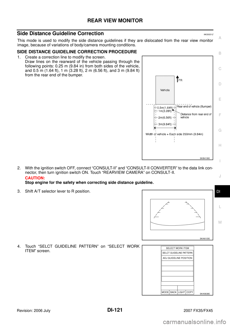
SIDE DISTANCE GUIDELINE CORRECTION PROCEDURE
1. Create a correction line to modify the screen.
Draw lines on the rearward of the vehicle passing through the
following points: 0.25 m (9.84 in) from both sides of the vehicle,
and 0.5 m (1.64 ft), 1 m (3.28 ft), 2 m (6.56 ft), and 3 m (9.84 ft)
from the rear end of the bumper.
2. With the ignition switch OFF, connect “CONSULT-II” and “CONSULT-II CONVERTER” to the data link con- nector, then turn ignition switch ON. Touch “REARVIEW CAMERA” on CONSULT-II.
CAUTION:
Stop engine for the safety when correcting side distance guideline.
3. Shift A/T selector lever to R position.
4. Touch “SELCT GUIDELINE PATTERN” on “SELECT WORK ITEM” screen.
SKIB4106E
SKIA6103E
SKIA5638E
Page 1369 of 4366
REAR VIEW MONITOR DI-123
C
D E
F
G H
I
J
L
M A
B
DI
Revision: 2006 July 2007 FX35/FX45
Power Supply and Ground Circuit InspectionNKS00320
1. CHECK FUSE
Make sure the fuses for rear view camera control unit is blown.
OK or NG
OK >> GO TO 2.
NG >> Be sure to eliminate cause of malfunction before installing new fuse. Refer to PG-3, "
POWER
SUPPLY ROUTING CIRCUIT" .
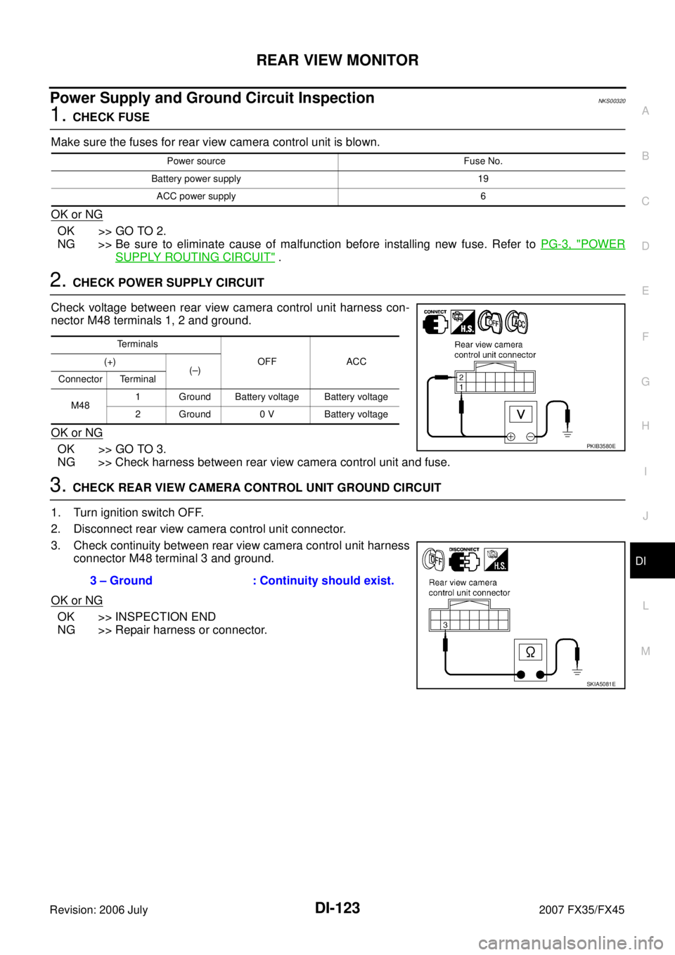
2. CHECK POWER SUPPLY CIRCUIT
Check voltage between rear view camera control unit harness con-
nector M48 terminals 1, 2 and ground.
OK or NG
OK >> GO TO 3.
NG >> Check harness between rear view camera control unit and fuse.
3. CHECK REAR VIEW CAMERA CONTROL UNIT GROUND CIRCUIT
1. Turn ignition switch OFF.
2. Disconnect rear view camera control unit connector.
3. Check continuity between rear view camera control unit harness connector M48 terminal 3 and ground.
OK or NG
OK >> INSPECTION END
NG >> Repair harness or connector.
Power source Fuse No.
Battery power supply 19 ACC power supply 6
Terminals OFF ACC
(+)
(–)
Connector Terminal
M48 1 Ground Battery voltage Battery voltage
2 Ground 0 V Battery voltage
PKIB3580E
3 – Ground : Continuity should exist.
SKIA5081E
Page 1370 of 4366
DI-124
REAR VIEW MONITOR
Revision: 2006 July 2007 FX35/FX45
Rear View Is Not Displayed With The A/T Selector Lever In R-PositionNKS00321
1. BACK-UP LAMP INSPECTION
1. Turn ignition switch ON.
2. Shift A/T selector lever to R position.
Does back-up lamp illuminate?
YES >> GO TO 2.
NO >> Check back-up lamp system. Refer to LT- 1 2 9 , "
BACK-UP LAMP" in LT section.
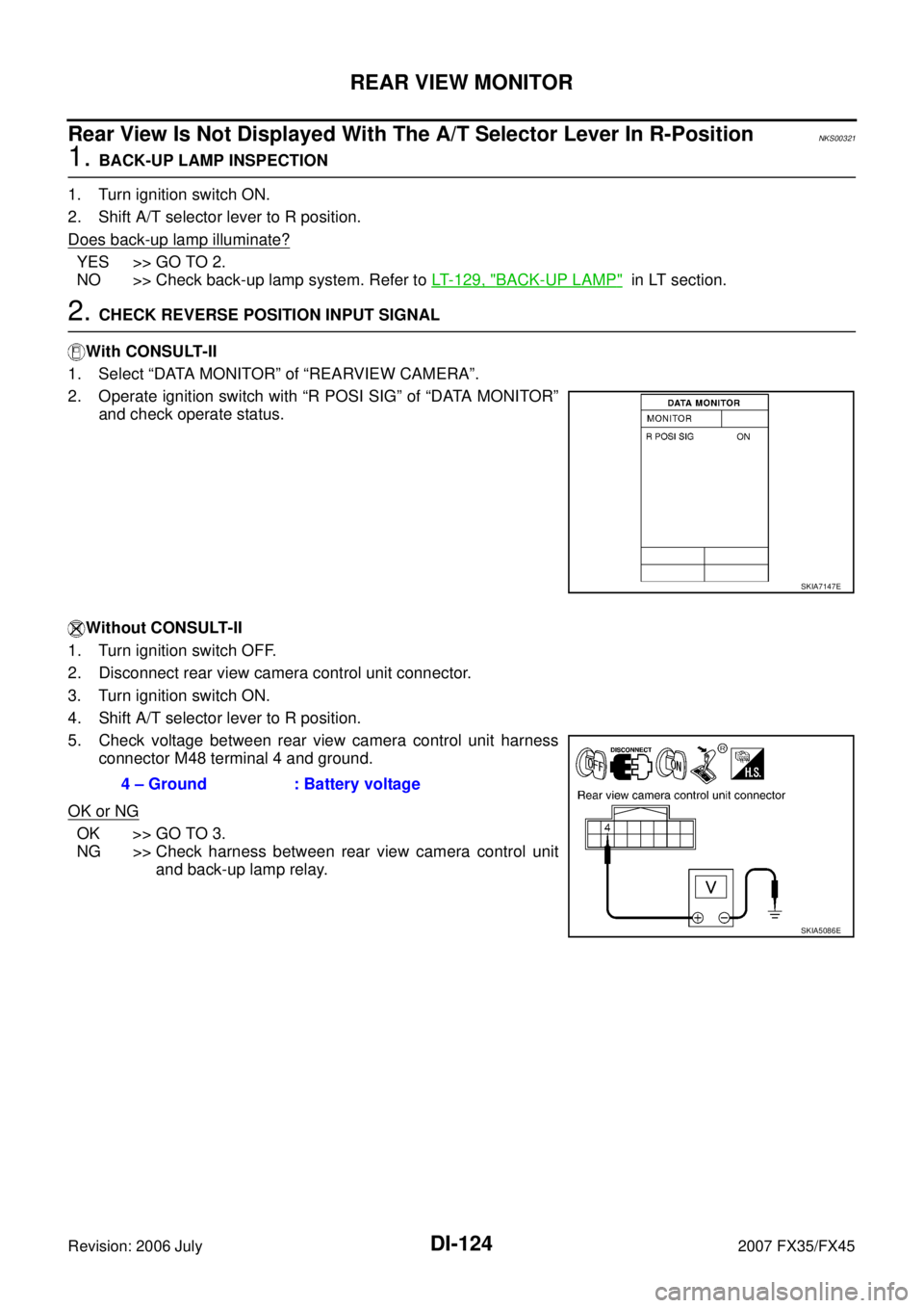
2. CHECK REVERSE POSITION INPUT SIGNAL
With CONSULT-II
1. Select “DATA MONITOR” of “REARVIEW CAMERA”.
2. Operate ignition switch with “R POSI SIG” of “DATA MONITOR” and check operate status.
Without CONSULT-II
1. Turn ignition switch OFF.
2. Disconnect rear view camera control unit connector.
3. Turn ignition switch ON.
4. Shift A/T selector lever to R position.
5. Check voltage between rear view camera control unit harness connector M48 terminal 4 and ground.
OK or NG
OK >> GO TO 3.
NG >> Check harness between rear view camera control unit
and back-up lamp relay.
SKIA7147E
4 – Ground : Battery voltage
SKIA5086E
Page 1371 of 4366
REAR VIEW MONITOR DI-125
C
D E
F
G H
I
J
L
M A
B
DI
Revision: 2006 July 2007 FX35/FX45
3. CHECK DISPLAY CONTROL UNIT OUTPUT SIGNAL
1. Turn ignition switch OFF.
2. Disconnect rear view camera control unit connector.
3. Turn ignition switch ON.
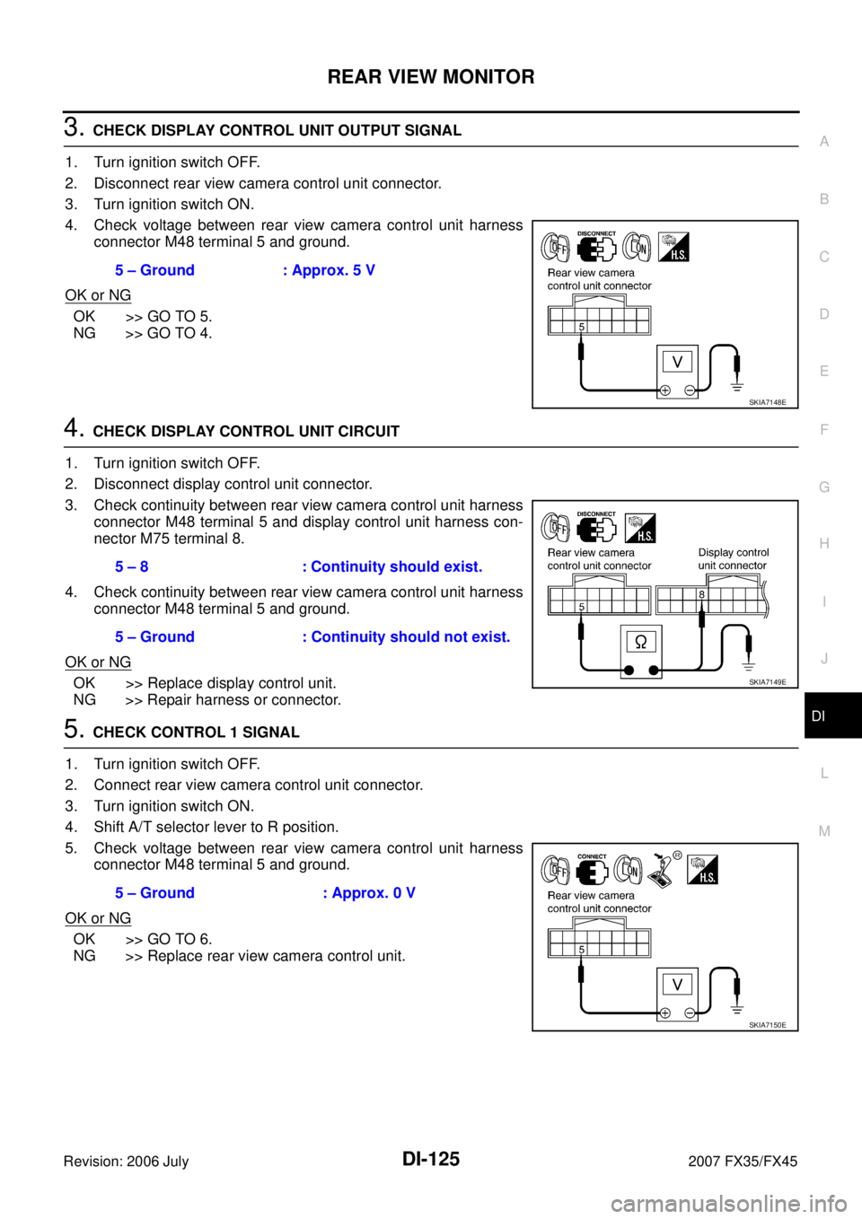
4. Check voltage between rear view camera control unit harness connector M48 terminal 5 and ground.
OK or NG
OK >> GO TO 5.
NG >> GO TO 4.
4. CHECK DISPLAY CONTROL UNIT CIRCUIT
1. Turn ignition switch OFF.
2. Disconnect display control unit connector.
3. Check continuity between rear view camera control unit harness connector M48 terminal 5 and display control unit harness con-
nector M75 terminal 8.
4. Check continuity between rear view camera control unit harness connector M48 terminal 5 and ground.
OK or NG
OK >> Replace display control unit.
NG >> Repair harness or connector.
5. CHECK CONTROL 1 SIGNAL
1. Turn ignition switch OFF.
2. Connect rear view camera control unit connector.
3. Turn ignition switch ON.
4. Shift A/T selector lever to R position.
5. Check voltage between rear view camera control unit harness connector M48 terminal 5 and ground.
OK or NG
OK >> GO TO 6.
NG >> Replace rear view camera control unit. 5 – Ground : Approx. 5 V
SKIA7148E
5 – 8 : Continuity should exist.
5 – Ground : Continuity should not exist.
SKIA7149E
5 – Ground : Approx. 0 V
SKIA7150E