Page 339 of 4366
ON-VEHICLE SERVICE AT-255
D E
F
G H
I
J
K L
M A
B
AT
Revision: 2006 July 2007 FX35/FX45
INSTALLATION
CAUTION:
After completing installation, check A/T position, A/T fluid leakage and A/F fluid level. Refer to AT- 2 3 1 ,
"Checking of A/T Position" , AT- 1 3 , "Checking A/T Fluid" .
1. As shown in the figure, use a drift to drive rear oil seal into the rear extension until it is flush.
CAUTION:
�Do not reuse rear oil seal.
�Apply ATF to rear oil seal.
2. Install return spring to parking pawl.
3. Install parking pawl (with return spring) and pawl shaft to rear extension.
4. Install parking actuator support to rear extension.
SCIA5311E
SCIA2445E
SCIA3424E
SCIA3423E
Page 340 of 4366
AT-256
ON-VEHICLE SERVICE
Revision: 2006 July 2007 FX35/FX45
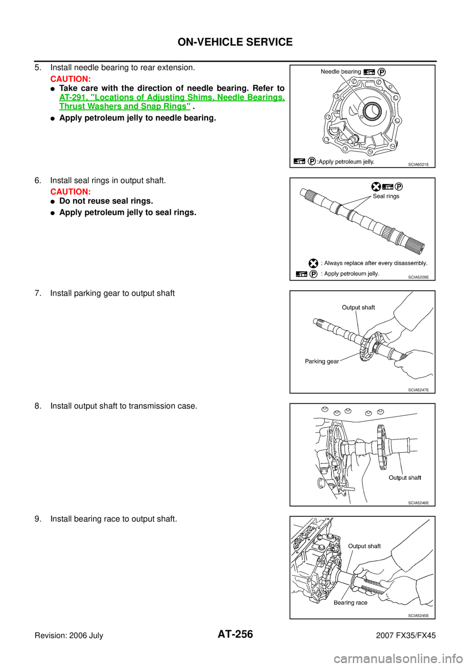
5. Install needle bearing to rear extension.
CAUTION:
�Take care with the direction of needle bearing. Refer to
AT- 2 9 1 , "
Locations of Adjusting Shims, Needle Bearings,
Thrust Washers and Snap Rings" .
�Apply petroleum jelly to needle bearing.
6. Install seal rings in output shaft. CAUTION:
�Do not reuse seal rings.
�Apply petroleum jelly to seal rings.
7. Install parking gear to output shaft
8. Install output shaft to transmission case.
9. Install bearing race to output shaft.
SCIA6021E
SCIA5209E
SCIA5247E
SCIA5246E
SCIA5245E
Page 341 of 4366

ON-VEHICLE SERVICE AT-257
D E
F
G H
I
J
K L
M A
B
AT
Revision: 2006 July 2007 FX35/FX45
10. Apply recommended sealant (Genuine Anaerobic Liquid Gasket
or equivalent. Refer to GI-48, "
Recommended Chemical Prod-
ucts and Sealants" .) to rear extension assembly as shown in
the figure.
CAUTION:
Completely remove all moisture, oil and old sealant, etc.
from the transmission case and rear extension assembly
mounting surfaces.
11. Install rear extension assembly to transmission case. (With nee- dle bearing.)
CAUTION:
Insert the tip of parking rod between the parking pawl and
the parking actuator support when assembling the rear
extension assembly.
12. Tighten rear extension assembly mounting bolts to specified torque. Refer to AT- 2 5 0 , "
COMPONENTS" .
CAUTION:
Do not reuse self-sealing bolts.
13. Install engine mounting insulator (rear). Refer to AT- 2 6 6 , "
Removal and Installation (2WD Models)" .
14. Install rear engine mounting member. Refer to AT- 2 6 6 , "
Removal and Installation (2WD Models)" .
15. Install control rod. Refer to AT- 2 3 0 , "
Control Rod Removal and Installation" .
16. Install rear propeller shaft. Refer to PR-9, "
Removal and Installation" .
17. Install exhaust front tube and center muffler. Refer to EX-3, "
Components" .
18. Install drain plug in oil pan, and then tighten drain plug to the specified torque. Refer to AT- 2 3 9 , "
COMPO-
NENTS" .
CAUTION:
Do not reuse drain plug gasket.
19. Pour ATF into A/T assembly. Refer to AT- 1 2 , "
Changing A/T Fluid" .
SCIA8228E
SCIA3431E
SCIA6941E
Page 342 of 4366

AT-258
ON-VEHICLE SERVICE
Revision: 2006 July 2007 FX35/FX45
Rear Oil SealNCS001IH
REMOVAL
1. Remove center muffler with power tool. Refer to EX-3, "Compo-
nents" .
2. Remove rear propeller shaft. Refer to PR-9, "
Removal and
Installation" .
3. Remove front propeller shaft (AWD models). Refer to PR-5,
"Removal and Installation" .
4. Remove transfer assembly from A/T assembly (AWD models). Refer to TF-44, "
Removal and Installation" .
5. Remove rear oil seal using a flat-bladed screwdriver. CAUTION:
Be careful not to scratch rear extension assembly (2WD
models) or adapter case assembly (AWD models).
INSTALLATION
CAUTION:
After completing installation, check A/T fluid leakage and A/T fluid level. Refer to AT- 1 3 , "
Checking A/T
Fluid" .
1. As shown in the figure, use the drift to drive rear oil seal into rear extension assembly (2WD models) or adapter case assembly
(AWD models) until it is flush.
CAUTION:
�Do not reuse rear oil seal.
�Apply ATF to rear oil seal.
2. Install transfer assembly to A/T assembly (AWD models). Refer to TF-44, "
Removal and Installation" .
3. Install front propeller shaft (AWD models). Refer to PR-5,
"Removal and Installation" .
4. Install rear propeller shaft. Refer to PR-9, "
Removal and Installa-
tion" .
5. Install center muffler. Refer to EX-3, "
Components" .
SCIA5410E
SCIA5411E
Page 343 of 4366
NCS001II
COMPONENTS
REMOVAL
1. Disconnect the battery")
ON-VEHICLE SERVICE AT-259
D E
F
G H
I
J
K L
M A
B
AT
Revision: 2006 July 2007 FX35/FX45
Revolution Sensor Components (2WD Models Only)NCS001II
COMPONENTS
REMOVAL
1. Disconnect the battery cable from the negative terminal.
2. Drain ATF through drain plug.
3. Remove front cross bar. Refer to FSU-8, "
Removal and Installation" .
4. Remove exhaust front tube and center muffler with power tool. Refer to EX-3, "
Components" .
5. Remove rear propeller shaft. Refer to PR-9, "
Removal and Installation" .
6. Remove control rod. Refer to AT- 2 3 0 , "
Control Rod Removal and Installation" .
1. Rear extension 2. A/T 3. Oil pan gasket
4. Clip 5. Oil pan mounting bolt 6. Oil pan
7. Drain plug 8. Drain plug gasket 9. Revolution sensor
10. Self-sealing bolt
Refer to GI section to make sure icons (symbol marks) in the figure. Refer to GI-11, "
Components" .
However, refer to the following symbol for others.
*: Apply Genuine Anaerobic Liquid Gasket or equivalent. Refer to GI-48, "Recommended Chemical Products and Sealants"
SCIA8043E
Page 344 of 4366
, oil pan (2) and oil pan gasket.
�: Vehicle front
�: Bolt (22)
�Drain plug (3)
8. Check foreign materials in oil pan t")
AT-260
ON-VEHICLE SERVICE
Revision: 2006 July 2007 FX35/FX45
7. Remove clips (1), oil pan (2) and oil pan gasket.
�: Vehicle front
�: Bolt (22)
�Drain plug (3)
8. Check foreign materials in oil pan to help determine causes of malfunction. If the ATF is very dark, smells burned, or contains
foreign particles, the frictional material (clutches, band) may
need replacement. A tacky film that will not wipe clean indicates
varnish build up. Varnish can cause valves, servo, and clutches
to stick and can inhibit pump pressure.
�If frictional material is detected, perform A/T fluid cooler
cleaning. Refer to AT- 1 5 , "
A/T Fluid Cooler Cleaning" .
9. Support A/T assembly with a transmission jack. CAUTION:
When setting transmission jack, place wooden blocks to
prevent from damaging control valve with TCM and trans-
mission case.
10. Remove rear engine mounting member with power tool. Refer to AT- 2 6 6 , "
Removal and Installation (2WD
Models)" .
11. Remove tightening bolts for rear extension assembly and trans- mission case.
12. Tap rear extension assembly with soft hammer.
SCIA8117E
SCIA5199E
SCIA6941E
SCIA3432E
Page 345 of 4366
ON-VEHICLE SERVICE AT-261
D E
F
G H
I
J
K L
M A
B
AT
Revision: 2006 July 2007 FX35/FX45
13. Remove rear extension assembly from transmission case. (With
needle bearing.)
14. Disconnect revolution sensor connector. CAUTION:
Be careful not to damage connector
15. Straighten terminal clip to free revolution sensor harness.
16. Remove revolution sensor from transmission case. CAUTION:
�Do not subject it to impact by dropping or hitting it.
�Do not disassemble.
�Do not allow metal filings, etc. to get on the sensor's front
edge magnetic area.
�Do not place in an area affected by magnetism.
SCIA3431E
SCIA7524E
SCIA7525E
SCIA3997E
Page 346 of 4366

AT-262
ON-VEHICLE SERVICE
Revision: 2006 July 2007 FX35/FX45
INSTALLATION
CAUTION:
After completing installation, check A/T position, A/T fluid leakage and A/F fluid level. Refer to AT- 2 3 1 ,
"Checking of A/T Position" , AT- 1 3 , "Checking A/T Fluid" .
1. Install revolution sensor in transmission case, and then tighten revolution sensor mounting bolt to the specified torque. Refer to
AT- 2 5 9 , "
COMPONENTS" .
CAUTION:
�Do not subject it to impact by dropping or hitting it.
�Do not disassemble.
�Do not allow metal filings, etc. to get on the sensor's front
edge magnetic area.
�Do not place in an area affected by magnetism.
2. Connect revolution sensor connector.
3. Securely fasten revolution sensor harness with clip.
4. Apply recommended sealant (Genuine Anaerobic Liquid Gasket or equivalent. Refer to GI-48, "
Recommended Chemical Prod-
ucts and Sealants" .) to rear extension assembly as shown in
the figure.
CAUTION:
Completely remove all moisture, oil and old sealant, etc.
from transmission case and rear extension assembly
mounting surfaces.
SCIA3997E
SCIA7524E
SCIA7525E
SCIA8228E


14. Disconnect r")