Page 2954 of 4366
![INFINITI FX35 2007 Service Manual EM-162
[VQ35DE]
SERVICE DATA AND SPECIFICATIONS (SDS)
Revision: 2006 July 2007 FX35/FX45
MAIN BEARING
Unit: mm (in)
Undersize
Unit: mm (in)
Main Bearing Oil Clearance
Unit: mm (in)
*: Actual clearanc](/manual-img/42/57018/w960_57018-2953.png "INFINITI FX35 2007 Service Manual EM-162
[VQ35DE]
SERVICE DATA AND SPECIFICATIONS (SDS)
Revision: 2006 July 2007 FX35/FX45
MAIN BEARING
Unit: mm (in)
Undersize
Unit: mm (in)
Main Bearing Oil Clearance
Unit: mm (in)
*: Actual clearanc")
EM-162
[VQ35DE]
SERVICE DATA AND SPECIFICATIONS (SDS)
Revision: 2006 July 2007 FX35/FX45
MAIN BEARING
Unit: mm (in)
Undersize
Unit: mm (in)
Main Bearing Oil Clearance
Unit: mm (in)
*: Actual clearance Grade number UPR/LWR Thickness Width Identification color Remarks
0 — 2.000 - 2.003 (0.0787 - 0.0789)
19.9 - 20.1
(0.783 - 0.791) Black
Grade is the same
for upper and lower
bearings.
1 — 2.003 - 2.006 (0.0789 - 0.0790) Brown
2 — 2.006 - 2.009 (0.0790 - 0.0791) Green
3 — 2.009 - 2.012 (0.0791 - 0.0792) Yellow
4 — 2.012 - 2.015 (0.0792 - 0.0793) Blue
5 — 2.015 - 2.018 (0.0793 - 0.0794) Pink
6 — 2.018 - 2.021 (0.0794 - 0.0796) Purple
7 — 2.021 - 2.024 (0.0796 - 0.0797) White
01 UPR 2.003 - 2.006 (0.0789 - 0.0790) Brown
Grade is different
for upper and lower
bearings.
LWR 2.000 - 2.003 (0.0787 - 0.0789) Black
12 UPR 2.006 - 2.009 (0.0790 - 0.0791) Green
LWR 2.003 - 2.006 (0.0789 - 0.0790) Brown
23 UPR 2.009 - 2.012 (0.0791 - 0.0792) Yellow
LWR 2.006 - 2.009 (0.0790 - 0.0791) Green
34 UPR 2.012 - 2.015 (0.0792 - 0.0793) Blue
LWR 2.009 - 2.012 (0.0791 - 0.0792) Yellow
45 UPR 2.015 - 2.018 (0.0793 - 0.0794) Pink
LWR 2.012 - 2.015 (0.0792 - 0.0793) Blue
56 UPR 2.018 - 2.021 (0.0794 - 0.0796) Purple
LWR 2.015 - 2.018 (0.0793 - 0.0794) Pink
67 UPR 2.021 - 2.024 (0.0796 - 0.0797) White
LWR 2.018 - 2.021 (0.0794 - 0.0796) Purple
SEM175F
Items Thickness Main journal diameter
0.25 (0.0098) 2.132 - 2.140 (0.0839 - 0.0843) Grind so that bearing clearance is the specified value.
Items Standard Limit
Main bearing oil clearance 0.035 - 0.045 (0.0014 - 0.0018)* 0.065 (0.0026)
Page 3064 of 4366
![INFINITI FX35 2007 Service Manual EM-272
[VK45DE]
CYLINDER BLOCK
Revision: 2006 July 2007 FX35/FX45
CONNECTING ROD BEARING OIL CLEARANCE
Method by Calculation
�Install connecting rod bearings to connecting rod and cap, and
tighten c](/manual-img/42/57018/w960_57018-3063.png "INFINITI FX35 2007 Service Manual EM-272
[VK45DE]
CYLINDER BLOCK
Revision: 2006 July 2007 FX35/FX45
CONNECTING ROD BEARING OIL CLEARANCE
Method by Calculation
�Install connecting rod bearings to connecting rod and cap, and
tighten c")
EM-272
[VK45DE]
CYLINDER BLOCK
Revision: 2006 July 2007 FX35/FX45
CONNECTING ROD BEARING OIL CLEARANCE
Method by Calculation
�Install connecting rod bearings to connecting rod and cap, and
tighten connecting rod bolts to the specified torque. Refer to
EM-253, "
ASSEMBLY" for the tightening procedure.
�Measure the inner diameter of connecting rod bearing with
inside micrometer.
(Bearing oil clearance) = (Connecting rod bearing inner diameter) –
(Crankshaft pin journal diameter)
�If the calculated value exceeds the limit, select proper connecting rod bearing according to connecting rod
big end diameter and crankshaft pin journal diameter to obtain the specified bearing oil clearance. Refer
to EM-260, "
HOW TO SELECT CONNECTING ROD BEARING" .
Method of Using Plastigage
�Remove oil and dust on crankshaft pin journal and the surfaces of each bearing completely.
�Cut plastigage slightly shorter than the bearing width, and place it in crankshaft axial direction, avoiding oil
holes.
�Install connecting rod bearings to connecting rod and cap, and tighten connecting rod bolts to the speci-
fied torque. Refer to EM-253, "
ASSEMBLY" for the tightening procedure.
CAUTION:
Do not rotate crankshaft.
�Remove connecting rod bearing cap and bearing, and using
scale on plastigage bag, measure the plastigage width.
NOTE:
The procedure when the measured value exceeds the limit is
same as that described in the “Method by Calculation”. Standard : 0.020 - 0.045 mm (0.0008 - 0.0018 in)
(actual clearance)
Limit : 0.055 mm (0.0022 in)
PBIC1642E
PBIC1149E
Page 3065 of 4366
![INFINITI FX35 2007 Service Manual CYLINDER BLOCK EM-273
[VK45DE]
C
D E
F
G H
I
J
K L
M A
EM
Revision: 2006 July 2007 FX35/FX45
MAIN BEARING OIL CLEARANCE
Method by Calculation
�Install main bearings to cylinder block and](/manual-img/42/57018/w960_57018-3064.png "INFINITI FX35 2007 Service Manual CYLINDER BLOCK EM-273
[VK45DE]
C
D E
F
G H
I
J
K L
M A
EM
Revision: 2006 July 2007 FX35/FX45
MAIN BEARING OIL CLEARANCE
Method by Calculation
�Install main bearings to cylinder block and")
CYLINDER BLOCK EM-273
[VK45DE]
C
D E
F
G H
I
J
K L
M A
EM
Revision: 2006 July 2007 FX35/FX45
MAIN BEARING OIL CLEARANCE
Method by Calculation
�Install main bearings to cylinder block and main bearing caps,
and tighten main bearing cap bolts with main bearing to the
specified torque. Refer to EM-253, "
ASSEMBLY" for the tighten-
ing procedure.
�Measure the inner diameter of main bearing with bore gauge.
(Bearing clearance) = (Main bearing inner diameter) – (Crankshaft main journal diameter)
�If the calculated value exceeds the limit, select proper main bearing according to main bearing inner diam-
eter and crankshaft main journal diameter to obtain the specified bearing oil clearance. Refer to EM-261,
"HOW TO SELECT MAIN BEARING" .
Method of Using Plastigage
�Remove oil and dust on crankshaft main journal and the surfaces of each bearing completely.
�Cut plastigage slightly shorter than the bearing width, and place it in crankshaft axial direction, avoiding oil
holes.
�Install main bearings to cylinder block and main bearing caps, and tighten main bearing bolts with main
bearing to the specified torque. Refer to EM-253, "
ASSEMBLY" for the tightening procedure.
CAUTION:
Do not rotate crankshaft.
�Remove main bearing caps and bearings, and using scale on
plastigage bag, measure the plastigage width.
NOTE:
The procedure when the measured value exceeds the limit is
same as that described in the “Method by Calculation”.
PBIC1644E
Standard
No . 1 and 5 journal : 0.001 - 0.011 mm (0.00004 - 0.0004 in)
No. 2, 3 and 4 journal : 0.007 - 0.017 mm (0.0003 - 0.0007 in)
Limit No . 1 and 5 journal : 0.021 mm (0.0008 in)
No. 2, 3 and 4 journal : 0.027 mm (0.0011 in)
PBIC1149E
Page 3233 of 4366
IDENTIFICATION INFORMATION GI-51
C
D E
F
G H
I
J
K L
M B
GI
Revision: 2006 July 2007 FX35/FX45
ENGINE SERIAL NUMBER
AUTOMATIC TRANSMISSION NUMBER
Dimensions NAS0006Y
Unit: mm (in)
Wheels & Tires NAS0006Z
PAIA0110E
PA I A 0 111 E
PAIA0054E
Overall length 4,803 (189.1)
Overall width 1,925 (75.8)
Overall height 1,672.6 (65.9)
Front tread 1,592 (62.7)
Rear tread 1,642 (64.6)
Wheelbase 2,850 (112.2)
Application Conventional Spare
Road wheel/offset mm (in) 18 X 8JJ Aluminum/40 (1.57)
20 X 8JJ Aluminum/40 (1.57) T175/90D18 110M
Tire size P265/60R18 109V
P265/50R20 106V
Page 4229 of 4366

TROUBLE DIAGNOSIS TF-25
C E F
G H
I
J
K L
M A
B
TF
Revision: 2006 July 2007 FX35/FX45
ACTIVE TEST MODE
Description
Use this mode to determine and identify the details of a malfunction based on self-diagnostic results or data
monitor. AWD control unit gives drive signal to actuator with receiving command from CONSULT-II to check
operation of actuator.
Test Item
CAUTION:
Do not continuously energize for a long time.
AWD CONTROL UNIT PART NUMBER
Ignore the AWD control unit part number displayed in the “ECU PART NUMBER”.
Refer to parts catalog to order the AWD control unit.
Frequency
(Hz) ––
×
The value measured by the pulse probe is dis-
played.
DUTY-HI (high)
(%) ––
×
DUTY-LOW (low)
(%) ––
×
PLS WIDTH-HI
(msec) ––
×
PLS WIDTH-LOW
(msec) ––
×
Monitored item (Unit)
Monitor item selection
Remarks
ECU INPUT
SIGNALS MAIN
SIGNALS SELECTION
FROM MENU
Test item Condition Description
ETS S/V
(Detects AWD solenoid valve)
�Vehicle stopped
�Engine running
�No DTC detected
�Change command current value to AWD solenoid, and then change driv-
ing mode. (Monitor value is normal if it is within approximately ±10% of
command value.)
Qu: Increase current value in increments of 0.20A
Qd: Decrease current value in increments of 0.20A
UP: Increase current value in increments of 0.02A
DOWN: Decrease current value in increments of 0.02A
Page 4359 of 4366
REAR WIPER AND WASHER SYSTEM WW-53
C
D E
F
G H
I
J
L
M A
B
WW
Revision: 2006 July 2007 FX35/FX45
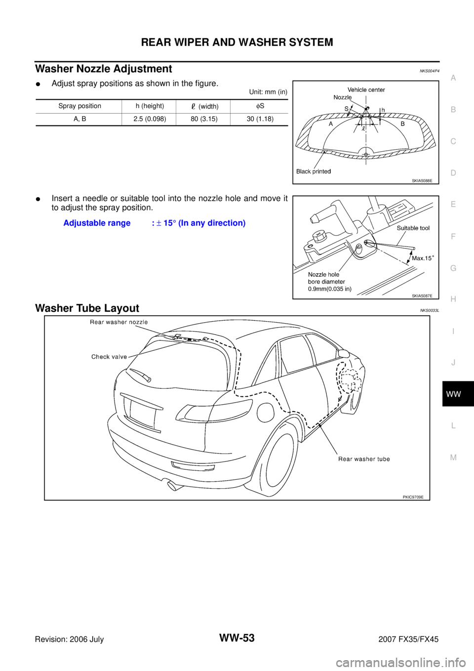
Washer Nozzle AdjustmentNKS004P4
�Adjust spray positions as shown in the figure.
Unit: mm (in)
�Insert a needle or suitable tool into the nozzle hole and move it
to adjust the spray position.
Washer Tube LayoutNKS0033L
Spray position h (height) (width) φ
S
A, B 2.5 (0.098) 80 (3.15) 30 (1.18)
SKIA5088E
Adjustable range : ± 15 ° (In any direction)
SKIA5087E
PKIC9709E

Whee")