Page 2826 of 4366
![INFINITI FX35 2007 Service Manual EM-34
[VQ35DE]
OIL PAN AND OIL STRAINER
Revision: 2006 July 2007 FX35/FX45
�Tighten mounting bolts in numerical order as shown in the fig-
ure.
�There are two types of mounting bolts. Refer to the fo](/manual-img/42/57018/w960_57018-2825.png "INFINITI FX35 2007 Service Manual EM-34
[VQ35DE]
OIL PAN AND OIL STRAINER
Revision: 2006 July 2007 FX35/FX45
�Tighten mounting bolts in numerical order as shown in the fig-
ure.
�There are two types of mounting bolts. Refer to the fo")
EM-34
[VQ35DE]
OIL PAN AND OIL STRAINER
Revision: 2006 July 2007 FX35/FX45
�Tighten mounting bolts in numerical order as shown in the fig-
ure.
�There are two types of mounting bolts. Refer to the following
for locating bolts.
f. Tighten transmission joint bolts. Refer to AT- 2 6 6 , "
TRANSMISSION ASSEMBLY" .
2. Install oil strainer to oil pump.
3. Install oil pan (lower) as follows:
a. Use scraper to remove old liquid gasket from mating surfaces.
�Also remove old liquid gasket from mating surface of oil pan
(upper).
�Remove old liquid gasket from the bolt holes and thread.
CAUTION:
Do not scratch or damage the mating surfaces when clean-
ing off old liquid gasket.
b. Apply a continuous bead of liquid gasket with the tube presser [SST: WS39930000 ( — )] to the oil pan (lower) as shown in
the figure.
Use Genuine RTV Silicone Sealant or equivalent. Refer to
GI-48, "
RECOMMENDED CHEMICAL PRODUCTS AND
SEALANTS" .
CAUTION:
Attaching should be done within 5 minutes after coating.
c. Install oil pan (lower). M8
× 100 mm (3.94 in) : 5, 7, 8, 11
M8 × 25 mm (0.98 in) : Except the above
PBIC0783E
SEM958F
PBIC2657E
Page 2831 of 4366
OIL PAN AND OIL STRAINER EM-39
[VQ35DE]
C
D E
F
G H
I
J
K L
M A
EM
Revision: 2006 July 2007 FX35/FX45
a. Use a scraper to remove old liquid gasket from mating surfaces.
CAUTION:
Do not scratch or damage the mating surfaces when clean-
ing off old liquid gasket.
�Also remove old liquid gasket from mating surface of cylinder
block.
�Remove old liquid gasket from the bolt holes and threads.
b. Install new oil pan gaskets.
�Apply liquid gasket to oil pan gaskets as shown in the figure.
Use Genuine RTV Silicone Sealant or equivalent. Refer to
GI-48, "
RECOMMENDED CHEMICAL PRODUCTS AND
SEALANTS" .
�To install, align protrusion of oil pan gasket with notches of
front timing chain case and rear oil seal retainer.
�Install oil pan gasket with smaller arc to front timing chain
case side.
c. Install new O-rings on the bottom of cylinder block and oil pump.
MEM108A
PBIC2630E
PBIC1145E
PBIC1144E
Page 2832 of 4366
![INFINITI FX35 2007 Service Manual EM-40
[VQ35DE]
OIL PAN AND OIL STRAINER
Revision: 2006 July 2007 FX35/FX45
d. Apply a continuous bead of liquid gasket with the tube presser
[SST: WS39930000 ( — )] to the cylinder block mating sur](/manual-img/42/57018/w960_57018-2831.png "INFINITI FX35 2007 Service Manual EM-40
[VQ35DE]
OIL PAN AND OIL STRAINER
Revision: 2006 July 2007 FX35/FX45
d. Apply a continuous bead of liquid gasket with the tube presser
[SST: WS39930000 ( — )] to the cylinder block mating sur")
EM-40
[VQ35DE]
OIL PAN AND OIL STRAINER
Revision: 2006 July 2007 FX35/FX45
d. Apply a continuous bead of liquid gasket with the tube presser
[SST: WS39930000 ( — )] to the cylinder block mating sur-
face of oil pan (upper) to a limited portion as shown in the figure.
Use Genuine RTV Silicone Sealant or equivalent. Refer to
GI-48, "
RECOMMENDED CHEMICAL PRODUCTS AND
SEALANTS" .
CAUTION:
�For bolt holes with marks (5 locations), apply liquid
gasket outside the holes.
�Apply a bead of 4.5 to 5.5 mm (0.177 to 0.217 in) in diame-
ter to area “A”.
�Attaching should be done within 5 minutes after coating.
e. Install oil pan (upper). CAUTION:
Install avoiding misalignment of both oil pan gasket and O-rings.
�Tighten mounting bolts in numerical order as shown in the fig-
ure.
�There are two types of mounting bolts. Refer to the following
for locating bolts.
f. Tighten transmission joint bolts. Refer to AT- 2 6 6 , "
TRANSMISSION ASSEMBLY" .
3. Install oil strainer to oil pump.
4. Install oil pan (lower) as follows:
a. Use scraper to remove old liquid gasket from mating surfaces.
�Also remove old liquid gasket from mating surface of oil pan
(upper).
�Remove old liquid gasket from the bolt holes and thread.
CAUTION:
Do not scratch or damage the mating surfaces when clean-
ing off old liquid gasket. M8
× 100 mm (3.94 in) : 5, 7, 8, 11
M8 × 25 mm (0.98 in) : Except the above
PBIC2300E
PBIC0783E
SEM958F
Page 2833 of 4366
![INFINITI FX35 2007 Service Manual OIL PAN AND OIL STRAINER EM-41
[VQ35DE]
C
D E
F
G H
I
J
K L
M A
EM
Revision: 2006 July 2007 FX35/FX45
b. Apply a continuous bead of liquid gasket with the tube presser
[SST: WS39930000 (](/manual-img/42/57018/w960_57018-2832.png "INFINITI FX35 2007 Service Manual OIL PAN AND OIL STRAINER EM-41
[VQ35DE]
C
D E
F
G H
I
J
K L
M A
EM
Revision: 2006 July 2007 FX35/FX45
b. Apply a continuous bead of liquid gasket with the tube presser
[SST: WS39930000 (")
OIL PAN AND OIL STRAINER EM-41
[VQ35DE]
C
D E
F
G H
I
J
K L
M A
EM
Revision: 2006 July 2007 FX35/FX45
b. Apply a continuous bead of liquid gasket with the tube presser
[SST: WS39930000 ( — )] to the oil pan (lower) as shown in
the figure.
Use Genuine RTV Silicone Sealant or equivalent. Refer to
GI-48, "
RECOMMENDED CHEMICAL PRODUCTS AND
SEALANTS" .
CAUTION:
Attaching should be done within 5 minutes after coating.
c. Install oil pan (lower).
�Tighten mounting bolts in numerical order as shown in the fig-
ure.
5. Install oil pan drain plug.
�Refer to the figure of components of former page for installation direction of drain plug washer. Refer to
EM-35, "
Components (AWD Models)" .
6. Install in the reverse order of removal after this step.
NOTE:
At least 30 minutes after oil pan is installed, pour engine oil.
INSPECTION AFTER INSTALLATION
1. Check the engine oil level and adjust engine oil. Refer to LU-7, "ENGINE OIL" .
2. Start engine, and check there is no leak of engine oil.
3. Stop engine and wait for 10 minutes.
4. Check the engine oil level again. Refer to LU-7, "
ENGINE OIL" .
PBIC2657E
PBIC0782E
Page 2851 of 4366
FRONT TIMING CHAIN CASE EM-59
[VQ35DE]
C
D E
F
G H
I
J
K L
M A
EM
Revision: 2006 July 2007 FX35/FX45
�Apply a continuous bead of liquid gasket with the tube presser
[SST: WS39930000 ( — )] to front timing chain case as
shown in the figure.
Use Genuine RTV Silicone Sealant or equivalent. Refer to
GI-48, "
RECOMMENDED CHEMICAL PRODUCTS AND
SEALANTS".
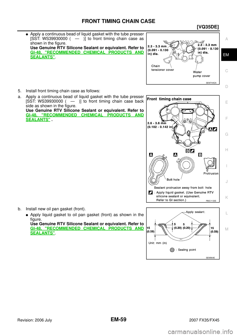
5. Install front timing chain case as follows:
a. Apply a continuous bead of liquid gasket with the tube presser [SST: WS39930000 ( — )] to front timing chain case back
side as shown in the figure.
Use Genuine RTV Silicone Sealant or equivalent. Refer to
GI-48, "
RECOMMENDED CHEMICAL PRODUCTS AND
SEALANTS" .
b. Install new oil pan gasket (front).
�Apply liquid gasket to oil pan gasket (front) as shown in the
figure.
Use Genuine RTV Silicone Sealant or equivalent. Refer to
GI-48, "
RECOMMENDED CHEMICAL PRODUCTS AND
SEALANTS".
SEM744GA
PBIC1133E
SEM964E
Page 2852 of 4366
![INFINITI FX35 2007 Service Manual EM-60
[VQ35DE]
FRONT TIMING CHAIN CASE
Revision: 2006 July 2007 FX35/FX45
�Align notch of front timing chain case with protrusion of oil pan
gasket.
�Apply liquid gasket with the tube presser [SST: W](/manual-img/42/57018/w960_57018-2851.png "INFINITI FX35 2007 Service Manual EM-60
[VQ35DE]
FRONT TIMING CHAIN CASE
Revision: 2006 July 2007 FX35/FX45
�Align notch of front timing chain case with protrusion of oil pan
gasket.
�Apply liquid gasket with the tube presser [SST: W")
EM-60
[VQ35DE]
FRONT TIMING CHAIN CASE
Revision: 2006 July 2007 FX35/FX45
�Align notch of front timing chain case with protrusion of oil pan
gasket.
�Apply liquid gasket with the tube presser [SST: WS39930000
( — )] to top surface of oil pan (upper) as shown in the fig-
ure.
Use Genuine RTV Silicone Sealant or equivalent. Refer to
GI-48, "
RECOMMENDED CHEMICAL PRODUCTS AND
SEALANTS" .
c. Install new O-rings on rear timing chain case.
d. Assemble front timing chain case as follows:
i. Fit lower end of front timing chain case tightly onto top face of oil pan (upper). From the fitting point, make entire front timing chain
case contact rear timing chain case completely.
CAUTION:
Be careful that oil pan gasket is in place.
ii. Since front timing chain case is offset for difference of bolt holes, tighten bolts temporarily with holding front timing chain case
from front and top as shown in the figure.
For bolt length and positions, refer to the step e.
iii. Same as the step ii, insert dowel pin with holding front timing chain case from front and top completely.
PBIC1114E
PBIC1099E
PBIC2548E
PBIC1100E
PBIC1115E
Page 2853 of 4366
![INFINITI FX35 2007 Service Manual FRONT TIMING CHAIN CASE EM-61
[VQ35DE]
C
D E
F
G H
I
J
K L
M A
EM
Revision: 2006 July 2007 FX35/FX45
e. Tighten mounting bolts to the specified torque in numerical order
as shown in the](/manual-img/42/57018/w960_57018-2852.png "INFINITI FX35 2007 Service Manual FRONT TIMING CHAIN CASE EM-61
[VQ35DE]
C
D E
F
G H
I
J
K L
M A
EM
Revision: 2006 July 2007 FX35/FX45
e. Tighten mounting bolts to the specified torque in numerical order
as shown in the")
FRONT TIMING CHAIN CASE EM-61
[VQ35DE]
C
D E
F
G H
I
J
K L
M A
EM
Revision: 2006 July 2007 FX35/FX45
e. Tighten mounting bolts to the specified torque in numerical order
as shown in the figure.
�There are two type of mounting bolts. Refer to the following
for locating bolts.
f. After all bolts tightened, retighten them to the specified torque in numerical order as shown in the figure.
6. Install two mounting bolts in front of oil pan (upper) in numerical order as shown in figure.
7. Install oil pan (lower). Refer to EM-30, "
OIL PAN AND OIL STRAINER" .
8. Install intake valve timing control covers as follows:
a. Install new seal rings in shaft grooves.
b. Apply a continuous bead of liquid gasket with the tube presser [SST: WS39930000 ( — )] to intake valve timing control cov-
ers as shown in the figure.
Use Genuine RTV Silicone Sealant or equivalent. Refer to
GI-48, "
RECOMMENDED CHEMICAL PRODUCTS AND
SEALANTS" .
c. Install new collared O-rings in front timing chain case oil hole (left and right sides).
d. Being careful not to move seal ring from the installation groove, align dowel pins on front timing chain case with the holes to install intake valve timing control covers. M8 bolts : 1, 2
: 28.4 N·m (2.9 kg-m, 21 ft-lb)
M6 bolts : Except the above
: 12.7 N·m (1.3 kg-m, 9 ft-lb)
: 17.2 N·m (1.8 kg-m, 13 ft-lb)
KBIA1303E
PBIC1116E
SBIA0492E
PBIC2631E
Page 2854 of 4366
![INFINITI FX35 2007 Service Manual EM-62
[VQ35DE]
FRONT TIMING CHAIN CASE
Revision: 2006 July 2007 FX35/FX45
e. Tighten mounting bolts in numerical order as shown in the fig-
ure.
9. Install crankshaft pulley as follows:
a. Fix cran](/manual-img/42/57018/w960_57018-2853.png "INFINITI FX35 2007 Service Manual EM-62
[VQ35DE]
FRONT TIMING CHAIN CASE
Revision: 2006 July 2007 FX35/FX45
e. Tighten mounting bolts in numerical order as shown in the fig-
ure.
9. Install crankshaft pulley as follows:
a. Fix cran")
EM-62
[VQ35DE]
FRONT TIMING CHAIN CASE
Revision: 2006 July 2007 FX35/FX45
e. Tighten mounting bolts in numerical order as shown in the fig-
ure.
9. Install crankshaft pulley as follows:
a. Fix crankshaft using the ring gear stopper [SST: KV10117700 (J44716)].
b. Install crankshaft pulley, taking care not to damage front oil seal.
�When press-fitting crankshaft pulley with plastic hammer, tap on its center portion (not circumference).
c. Tighten crankshaft pulley bolt.
d. Put a paint mark on crankshaft pulley aligning with angle mark on crankshaft pulley bolt.
e. Further tighten by 90 degrees. (Angle tightening)
�Check the tightening angle by referencing to the notches. The
angle between two notches is 90 degrees.
10. Rotate crankshaft pulley in normal direction (clockwise when viewed from front) to confirm it turns smoothly.
11. For the following operations, perform steps in the reverse order of removal. NOTE:
If hydraulic pressure inside chain tensioner drops after removal/installation, slack in the guide may gener-
ate a pounding noise during and just after engine start. However, this is normal. Noise will stop after
hydraulic pressure rises.
INSPECTION AFTER INSTALLATION
Inspection for Leaks
The followings are procedures for checking fluids leak, lubricates leak.
�Before starting engine, check oil/fluid levels including engine coolant and engine oil. If less than required
quantity, fill to the specified level. Refer to GI-48, "
RECOMMENDED CHEMICAL PRODUCTS AND
SEALANTS" .
�Use procedure below to check for fuel leakage.
–Turn ignition switch “ON” (with engine stopped). With fuel pressure applied to fuel piping, check for fuel
leakage at connection points.
–Start engine. With engine speed increased, check again for fuel leakage at connection points.
�Run engine to check for unusual noise and vibration.
NOTE:
If hydraulic pressure inside chain tensioner drops after removal/installation, slack in guide may generate a
pounding noise during and just after the engine start. However, this does not indicate an unusualness.
Noise will stop after hydraulic pressure rises.
PBIC0918E
: 44.1 N·m (4.5 kg-m, 33 ft-lb)
PBIC4821E
![INFINITI FX35 2007 Service Manual OIL PAN AND OIL STRAINER EM-39
[VQ35DE]
C
D E
F
G H
I
J
K L
M A
EM
Revision: 2006 July 2007 FX35/FX45
a. Use a scraper to remove old liquid gasket from mating surfaces.
CAUTION:
Do not](/manual-img/42/57018/w960_57018-2830.png "INFINITI FX35 2007 Service Manual OIL PAN AND OIL STRAINER EM-39
[VQ35DE]
C
D E
F
G H
I
J
K L
M A
EM
Revision: 2006 July 2007 FX35/FX45
a. Use a scraper to remove old liquid gasket from mating surfaces.
CAUTION:
Do not")