Page 3372 of 4366
![INFINITI FX35 2007 Service Manual LAN-8
[CAN FUNDAMENTAL]
TROUBLE DIAGNOSIS
Revision: 2006 July 2007 FX35/FX45
Symptom When Error Occurs in CAN Communication SystemNKS004MD
In CAN communication system, multiple units mutually transmit](/manual-img/42/57018/w960_57018-3371.png "INFINITI FX35 2007 Service Manual LAN-8
[CAN FUNDAMENTAL]
TROUBLE DIAGNOSIS
Revision: 2006 July 2007 FX35/FX45
Symptom When Error Occurs in CAN Communication SystemNKS004MD
In CAN communication system, multiple units mutually transmit")
LAN-8
[CAN FUNDAMENTAL]
TROUBLE DIAGNOSIS
Revision: 2006 July 2007 FX35/FX45
Symptom When Error Occurs in CAN Communication SystemNKS004MD
In CAN communication system, multiple units mutually transmit and receive signals. Each unit cannot transmit
and receive signals if any error occurs on CAN communication line. Under this condition, multiple control units
related to the root cause malfunction or go into fail-safe mode.
ERROR EXAMPLE
NOTE:
�Each vehicle differs in symptom of each unit under fail-safe mode and CAN communication line wiring.
�Refer to LAN-41, "Abbreviation List" for the unit abbreviation.
Example: TCM branch line open circuit
SKIB8738E
Unit name Symptom
ECM Engine torque limiting is affected, and shift harshness increases.
BCM Reverse warning chime does not sound.
EPS control unit Normal operation.
Combination meter
�Shift position indicator and OD OFF indicator turn OFF.
�Warning lamps turn ON.
ABS actuator and electric unit (control unit) Normal operation.
TCM No impact on operation.
IPDM E/R Normal operation.
Page 3374 of 4366
LAN-10
[CAN FUNDAMENTAL]
TROUBLE DIAGNOSIS
Revision: 2006 July 2007 FX35/FX45
Example: Main Line Between Data Link Connector and ABS Actuator and Electric Unit (Con-
trol Unit) Open Circuit
SKIB8740E
Unit name Symptom
ECM Engine torque limiting is affected, and shift harshness increases.
BCM
�Reverse warning chime does not sound.
�The front wiper moves under continuous operation mode even though the front
wiper switch being in the intermittent position.
EPS control unit The steering effort increases.
Combination meter
�The shift position indicator and OD OFF indicator turn OFF.
�The speedometer is inoperative.
�The odo/trip meter stops.
ABS actuator and electric unit (control unit) Normal operation.
TCM No impact on operation.
IPDM E/R When the ignition switch is ON,
�The headlamps (Lo) turn ON.
�The cooling fan continues to rotate.
Page 3375 of 4366
![INFINITI FX35 2007 Service Manual TROUBLE DIAGNOSIS LAN-11
[CAN FUNDAMENTAL]
C
D E
F
G H
I
J
L
M A
B
LAN
Revision: 2006 July 2007 FX35/FX45
Example: CAN-H, CAN-L Harness Short Circuit
SKIB8741E
Unit name Symptom
ECM
�Eng](/manual-img/42/57018/w960_57018-3374.png "INFINITI FX35 2007 Service Manual TROUBLE DIAGNOSIS LAN-11
[CAN FUNDAMENTAL]
C
D E
F
G H
I
J
L
M A
B
LAN
Revision: 2006 July 2007 FX35/FX45
Example: CAN-H, CAN-L Harness Short Circuit
SKIB8741E
Unit name Symptom
ECM
�Eng")
TROUBLE DIAGNOSIS LAN-11
[CAN FUNDAMENTAL]
C
D E
F
G H
I
J
L
M A
B
LAN
Revision: 2006 July 2007 FX35/FX45
Example: CAN-H, CAN-L Harness Short Circuit
SKIB8741E
Unit name Symptom
ECM
�Engine torque limiting is affected, and shift harshness increases.
�Engine speed drops.
BCM
�Reverse warning chime does not sound.
�The front wiper moves under continuous operation mode even though the front
wiper switch being in the intermittent position.
�The room lamp does not turn ON.
�The engine does not start (if an error or malfunction occurs while turning the igni-
tion switch is OFF.)
�The steering lock does not release (if an error or malfunction occurs while turning
the ignition switch is OFF.)
EPS control unit The steering effort increases.
Combination meter
�The tachometer and the speedometer do not move.
�Warning lamps turn ON.
�Indicator lamps do not turn ON.
ABS actuator and electric unit (control unit) Normal operation.
TCM No impact on operation.
IPDM E/R When the ignition switch is ON,
�The headlamps (Lo) turn ON.
�The cooling fan continues to rotate.
Page 3724 of 4366
MA-32
CHASSIS AND BODY MAINTENANCE
Revision: 2006 July 2007 FX35/FX45
Changing Transfer FluidNLS0006P
CAUTION:
When draining fluid, protect exhaust tube flange with cover.
1. Drain fluid from drain plug and refill with new gear fluid.
2. Check fluid level. CAUTION:
Carefully fill the fluid. (Fill up for Approx. 3 minutes.)
Checking Propeller ShaftNLS0006Q
Check propeller shaft for damage, looseness or grease leakage.
Checking Differential Gear OilNLS0006R
Check for oil leakage. Fluid grade:
Genuine Nissan Matic D ATF (Continental U.S. and
Alaska) or Canada NISSAN Automatic Transmis-
sion Fluid
Refer to MA-12, "
RECOMMENDED FLUIDS AND
LUBRICANTS" .
Fluid capacity:
: Approx. 1.25 (2-5/8 US pt, 2-1/4 lmp pt)
Drain plug:
: 29.4 N·m (3.0 kg-m, 22 ft-lb)
Filler plug:
: 35 N·m (3.6 kg-m, 26 ft-lb)SDIA2087E
Tightening torque: Refer to PR-7, "
REAR PROPELLER SHAFT"
SMA118A
SMA012C
Page 3727 of 4366

CHASSIS AND BODY MAINTENANCE MA-35
C
D E
F
G H
I
J
K
M A
B
MA
Revision: 2006 July 2007 FX35/FX45
Tire RotationNLS0006U
�After rotation the tires, adjust the tire pressure.
�Retighten the wheel nuts when the vehicle has been driven for
1,000 km (600 miles) (also in cases of a flat tire, etc.).
CAUTION:
�Do not include the T-type spare tire when rotating the tires.
�When installing wheels, tighten them diagonally by dividing
the work two to three times in order to prevent the wheels
from developing any distortion.
�Be careful not to tighten wheel nut at torque exceeding the
criteria for preventing strain of disc rotor.
Checking Brake Fluid Level and LeaksNLS0006V
�If fluid level is extremely low, check brake system for leaks.
Checking Brake Lines and CablesNLS0006W
�Check brake fluid lines and parking brake cables for improper
attachment, leaks, chafing, abrasions, deterioration, etc.
Changing Brake FluidNLS0006X
1. Drain brake fluid from each bleed valve.
2. Refill until new brake fluid comes out from each bleed valve. Use same procedure as in bleeding hydraulic system to refill
brake fluid.
Refer to BR-10, "
Bleeding Brake System" .
�Refill with recommended Genuine Nissan Super Heavy Duty
Brake Fluid or equivalent DOT 3 (US FMVSS No. 116).
Refer to MA-12, "
RECOMMENDED FLUIDS AND LUBRI-
CANTS" .
�Never reuse drained brake fluid.
�Be careful not to splash brake fluid on painted areas. Tightening torque of wheel nut
: 108 N·m (11 kg, 83 ft-lb)
SMA829C
SBR451D
SBR389C
SBR419C
Page 3739 of 4366
PARKING BRAKE CONTROL PB-5
C
D E
G H
I
J
K L
M A
B
PB
Revision: 2006 July 2007 FX35/FX45
12. Remove right and left rear cables installation nuts, bolts, and remove right and left rear cable assembly
from the vehicle.
INSTALLATION
1. Install in the reverse order of removal. Tighten the mounting bolts and nuts to the specified torque. Referto PB-4, "
Components" .
CAUTION:
Do not reuse adjusting nut after removing it.
2. Adjust parking brake. Refer to PB-3, "
ADJUSTMENT" .
Page 3829 of 4366
NOISE, VIBRATION AND HARSHNESS (NVH) TROUBLESHOOTING PR-3
C E F
G H
I
J
K L
M A
B
PR
Revision: 2006 July 2007 FX35/FX45
NOISE, VIBRATION AND HARSHNESS (NVH) TROUBLESHOOTINGPFP:00003
NVH Troubleshooting ChartNDS000AS
Use the chart below to help you find the cause of the symptom. If necessary, repair or replace these parts.
×: Applicable
Reference page
Front
PR-4—
—
—
—
PR-4PR-5
NVH in FFD and RFD section
NVH in FAX, RAX, FSU, and RSU section
NVH in WT section
NVH in WT section
NVH in RAX section
NVH in BR section
NVH in PS section
RearPR-7PR-11—
PR-8—
PR-7PR-10
Possible cause and SUSPECTED PARTS
Uneven rotating torque
Center bearing improper installation
Excessive center bearing axial end play
Center bearing mounting (insulator) cracks, damage or deterioration
Excessive joint angle
Rotation imbalance
Excessive runout
DIFFERENTIAL
AXLE AND SUSPENSION
TIRES
ROAD WHEEL
DRIVE SHAFT
BRAKES
STEERING
Symptom Noise
××××××××××××××
Shake × × ××××××
Vibration ××××××× ×× × ×
Page 3832 of 4366
PR-6
FRONT PROPELLER SHAFT
Revision: 2006 July 2007 FX35/FX45
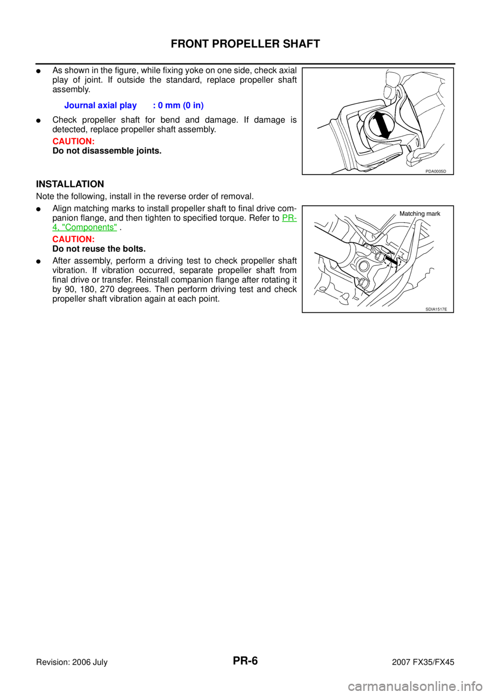
�As shown in the figure, while fixing yoke on one side, check axial
play of joint. If outside the standard, replace propeller shaft
assembly.
�Check propeller shaft for bend and damage. If damage is
detected, replace propeller shaft assembly.
CAUTION:
Do not disassemble joints.
INSTALLATION
Note the following, install in the reverse order of removal.
�Align matching marks to install propeller shaft to final drive com-
panion flange, and then tighten to specified torque. Refer to PR-
4, "Components" .
CAUTION:
Do not reuse the bolts.
�After assembly, perform a driving test to check propeller shaft
vibration. If vibration occurred, separate propeller shaft from
final drive or transfer. Reinstall companion flange after rotating it
by 90, 180, 270 degrees. Then perform driving test and check
propeller shaft vibration again at each point. Journal axial play : 0 mm (0 in)
PDA0005D
SDIA1517E
![INFINITI FX35 2007 Service Manual LAN-10
[CAN FUNDAMENTAL]
TROUBLE DIAGNOSIS
Revision: 2006 July 2007 FX35/FX45
Example: Main Line Between Data Link Connector and ABS Actuator and Electric Unit (Con-
trol Unit) Open Circuit
SKIB8740E](/manual-img/42/57018/w960_57018-3373.png "INFINITI FX35 2007 Service Manual LAN-10
[CAN FUNDAMENTAL]
TROUBLE DIAGNOSIS
Revision: 2006 July 2007 FX35/FX45
Example: Main Line Between Data Link Connector and ABS Actuator and Electric Unit (Con-
trol Unit) Open Circuit
SKIB8740E")


 TROUBLESHOOTING PR-3
C E F
G H
I
J
K L
M A
B
PR
Revision: 2006 July 2007 FX35/FX45
NOISE, VIBRATION AND HARSHNESS (NVH) TROUBLESHOOTINGPFP:00003
NVH Tr")