Page 3864 of 4366

PS-24
POWER STEERING GEAR AND LINKAGE
Revision: 2006 July 2007 FX35/FX45
INSPECTION AFTER DISASSEMBLY
Boot
Check boot for cracks and deformation. Replace it, if necessary.
Rack
Check rack for damage and wear. Replace it, if necessary.
Pinion Assembly
�Check pinion gear for damage and wear. Replace it, if necessary.
�Check bearing while rotating it. Replace bearing if bearing ball race was dented, worn, or damaged.
Gear Housing Assembly
Check gear housing assembly for damage and scratches (inner wall). Replace it, if necessary.
Outer Socket and Inner Socket
Swing Torque
�Hook a spring balance at the point shown in the figure. Confirm
if the reading is within the specification. When ball stud and
inner socket start moving the measured value must be within the
specification. If the reading is outside the specification, replace
socket.
Rotating Torque
�Using a preload gauge (SST), check if reading is within the
value specified below. If the value is outside the standard,
replace outer sockets.
SGIA0547E
Item Outer socket Inner socket
Measuring point Cotter pin hole of stud Shown as L: 83.2 mm (3.276 in)
Swing torque 0.3 − 2.9 N·m (0.03 − 0.29 kg-m, 3 − 25 in-lb) 1.0 − 7.8 N·m (0.11 − 0.79 kg-m, 9 − 69 in-lb)
Measuring value 4.84 − 46.7 N (0.5 − 4.8 kg, 1.0 - 10 lb) 12.1 − 93.7 N (1.2 − 9.6 kg, 3.0 − 21 lb)
Rotating torque 0.3 − 2.9 N·m (0.03 − 0.29 kg-m, 3 − 25 in-lb)
SST882B
Page 3866 of 4366
 × 100 mm (3.94 in) around rack")
PS-26
POWER STEERING GEAR AND LINKAGE
Revision: 2006 July 2007 FX35/FX45
a. To avoid damaging inner rack oil seal, wrap an OHP sheet
[approximately. 70 mm (2.76 in) × 100 mm (3.94 in) around rack
tooth. Place oil seal on sheet. Then, pull oil seal along with OHP
sheet until they pass the toothed section of rack, then remove it.
b. Insert rack oil seal (inner) to piston (rack Teflon ring) position and push retainer to adjust screw side with fingers lightly, and
then make rack move in gear housing assembly, install rack oil
seal (inner) to fit with gear housing assembly.
c. When installing outer rack oil seal, cover the end of rack with an OHP sheet [70 mm (2.76 in) × 100 mm (3.94 in)]. It will avoid
damaging rack oil seal. Then place oil seal on sheet. Pull rack oil
seal along with OHP sheet until they pass rack end. Then
remove OHP sheet.
d. Install end cover assembly to rack, move it to gear housing assembly.
5. Using a 45 mm (1.77 in) open head (suitable tool), tighten end cover assembly at the specified torque.
CAUTION:
Do not damage rack surface. If it is damaged, it may cause
oil leaks. Replace rack assembly.
6. After tightening end cover assembly, caulk cylinder at one point as shown in the figure using a punch. This will prevent end cover
from getting loose.
7. Install pinion assembly to gear housing assembly. CAUTION:
In order to protect oil seal from any damage, insert pinion
assembly out straightly.
8. Apply recommended fluid to O-ring. Install O-ring to rear cover.
9. Use a rear cover wrench (SST), install rear cover to gear hous- ing assembly.
SGIA0155E
SGIA0548E
SGIA0157E
SST081B
SGIA0158E
Page 3867 of 4366

POWER STEERING GEAR AND LINKAGE PS-27
C
D E
F
H I
J
K L
M A
B
PS
Revision: 2006 July 2007 FX35/FX45
10. Confirm projection on rear cover cap nearly fit with marking position on gear housing assembly.
11. Apply recommended thread locking sealant to the thread (2 turns thread), and then screw in the adjusting screw until it
reaches height “H” from gear housing assembly measured
before disassembling.
12. Rotate pinion ten times whole range of rack so that parts get to fit with each other.
13. Measure pinion rotating torque within from –180 ° to +180 °,
make preload gauge (SST) and torque adapter (SST) in rack
neutral position, then hold preload gauge (SST) at maximum
torque.
14. After loosening adjusting screw once, tighten it again with torque of 5.4 N·m (0.55 kg-m, 48 in-lb). After that loosen it within 20 ° to
40 °.
15. Measure pinion rotating torque with torque adapter (SST) and preload gauge (SST), then confirm whether it's reading is within
the specified value. If the reading is not within the specified
value, readjust screw angle with adjusting screw. Change gear
assembly to new one, if the reading is still not within the speci-
fied value or the rotating torque of adjusting screw is less than 5
N·m (0.51 kg-m, 44 in-lb).
16. Turn pinion fully to the end of the left with inner socket to gear housing assembly.
17. Set dial gauge to rack as shown in the figure. Measure vertical movement of rack when pinion is turned counterclockwise with
torque of 19.6 N·m (2.0 kg-m, 14 ft-lb). Check reading is within
the specified value. If reading is outside of the specification,
readjust screw angle with adjusting screw. If reading is still out-
side of specification, or if the rotating torque of adjusting screw is
less than 5 N·m (0.51 kg-m, 44 in-lb), replace steering gear
assembly.
SGIA0568E
SGIA0483E
Pinion rotating torque:
Around neutral position (within ±100 °)
Average “A”:
0.8 − 2.0 N·m (0.08 − 0.20 kg-m, 7 − 18 in-lb)
Other than above (more than ±100 °)
Maximum variation “B”:
2.3 N·m (0.23 kg-m, 20 in-lb)
SGIA0160E
SGIA0484E
Amount of vertical movement with rack Less than 0.265 mm (0.01 in)
Page 3869 of 4366
POWER STEERING GEAR AND LINKAGE PS-29
C
D E
F
H I
J
K L
M A
B
PS
Revision: 2006 July 2007 FX35/FX45
24. Tighten lightly inner socket in specified length “L”, then tighten
lock nut at specified torque. Refer to PS-21, "
Disassembly and
Assembly" . Reconfirm if inner socket length is within limit of
specified length “L”.
CAUTION:
Perform toe-in adjustment after this procedure. Length
achieved after toe-in adjustment is not necessary value
given here. Inner socket length “L” : 135.2 mm (5.32 in)
SGIA0167E
Page 3872 of 4366
NGS000C6
REMOVAL
1. Remove undercover from vehicle with power tool.
2. Loosen belt tensioner a")
PS-32
POWER STEERING OIL PUMP
Revision: 2006 July 2007 FX35/FX45
Removal and Installation (VQ35DE Models)NGS000C6
REMOVAL
1. Remove undercover from vehicle with power tool.
2. Loosen belt tensioner adjust screw, then remove belt from oil pump pulley. Refer to EM-15, "
DRIVE
BELTS" .
3. Drain power steering fluid from reservoir tank.
4. Remove piping of high pressure and low pressure (drain fluid from their pipings). Refer to PS-41,
"HYDRAULIC LINE" .
5. Remove mounting bolts, then remove power steering pump.
INSTALLATION
Refer to PS-41, "HYDRAULIC LINE" for tightening torque. Install in the reverse order removal.
�After installation, adjust belt tension. Refer to EM-15, "DRIVE BELTS" .
�After installation, bleed air. Refer to PS-8, "Air Bleeding Hydraulic System" .
Removal and Installation (VK45DE Models)NGS000C7
REMOVAL
1. Remove undercover from vehicle with power tool.
2. Remove power steering oil pump belt from auto tensioner. Refer to EM-174, "
DRIVE BELTS" .
3. Drain power steering fluid from reservoir tank.
4. Remove piping of high pressure and low pressure from power steering oil pump (drain fluid from their pip- ings). Refer to PS-41, "
HYDRAULIC LINE" .
5. Remove mounting bolts, then remove power steering pump.
INSTALLATION
Refer to PS-41, "HYDRAULIC LINE" for tightening torque. Install in the reverse order removal.
After installation, bleed air. Refer to PS-8, "
Air Bleeding Hydraulic System" .
NOTE:
Adjustment of belt tension is no necessary because engine of this model equips auto tensioner.
Page 3876 of 4366
PS-36
POWER STEERING OIL PUMP
Revision: 2006 July 2007 FX35/FX45
9. Using a hammer and a 10 mm (0.39 in) box, install rotor snap
ring to slot in pulley shaft.
CAUTION:
Be careful not to damage rotor and pulley shaft.
10. Match dowel pin A on flow control valve A, shown in the figure, with cutout B of rear side plate and install rear side plate to car-
tridge.
11. Apply recommended fluid to O-ring and install O-ring into rear side plate.
12. Apply recommended fluid to Teflon ring and Install Teflon ring into rear side plate.
13. Position rear cover on body assembly and tighten mounting bolts to specified torque.
14. Apply recommended fluid to O-ring and install O-ring into suc- tion pipe.
15. Install suction pipe into body assembly.
16. Install bracket to body assembly and tighten mounting bolts to specified torque.
SGIA0063E
SGIA0530E
Page 3880 of 4366
PS-40
POWER STEERING OIL PUMP
Revision: 2006 July 2007 FX35/FX45
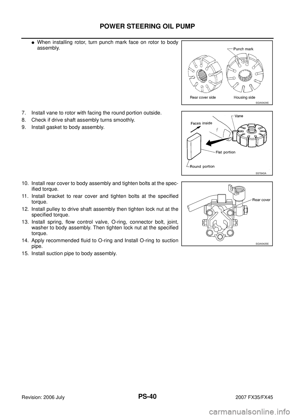
�When installing rotor, turn punch mark face on rotor to body
assembly.
7. Install vane to rotor with facing the round portion outside.
8. Check if drive shaft assembly turns smoothly.
9. Install gasket to body assembly.
10. Install rear cover to body assembly and tighten bolts at the spec- ified torque.
11. Install bracket to rear cover and tighten bolts at the specified torque.
12. Install pulley to drive shaft assembly then tighten lock nut at the specified torque.
13. Install spring, flow control valve, O-ring, connector bolt, joint, washer to body assembly. Then tighten lock nut at the specified
torque.
14. Apply recommended fluid to O-ring and Install O-ring to suction pipe.
15. Install suction pipe to body assembly.
SGIA0424E
SST843A
SGIA0425E
Page 3884 of 4366

PS-44
HYDRAULIC LINE
Revision: 2006 July 2007 FX35/FX45
Removal and InstallationNGS000CB
VQ35DE MODELS
�Refer to PS-41, "Components" for tightening torque. Install in the reverse order of removal.
NOTE:
Refer to component parts location and do not reuse non-reusable parts.
�Confirm with mating marking that if it is in phase with hose and
clamp, then correct if needs.
�To install eye joint, join projection of eye joint into notch of power
steering pump, and attach eye joint to power steering pump
properly. Then, tighten eye bolt by hands fully, and tighten it with
a specified torque.
�Connect harness connector into pressure sensor securely.
VK45DE MODELS
�Refer to PS-41, "Components" for tightening torque. Install in the reverse order of removal.
NOTE:
Refer to component parts location and do not reuse non-reusable parts.
�Confirm with mating marking that if it is in phase with hose and
clamp, then correct if needs.
�To install eye joint, join projection of eye joint into notch of power
steering pump, and attach eye joint to power steering pump
properly. Then, tighten eye bolt by hands fully, and tighten it with
a specified torque.
SGIA0563E
SGIA0533E
SGIA0563E
SGIA0537E

 box, install rotor snap
ring to slot in pulley shaft.
CAUTION:
Be careful not to damage roto")