Page 325 of 4366
ON-VEHICLE SERVICE AT-241
D E
F
G H
I
J
K L
M A
B
AT
Revision: 2006 July 2007 FX35/FX45
11. Disconnect A/T fluid temperature sensor 2 connector (1).
CAUTION:
Be careful not to damage connector.
12. Straighten terminal clips ( ) to free terminal cord assembly and A/T fluid temperature sensor 2 harness.
13. Disconnect revolution sensor connector. CAUTION:
Be careful not to damage connector.
14. Straighten terminal clip to free revolution sensor harness.
15. Remove bolts A, B and C from control valve with TCM.
�: Vehicle front
16. Remove control valve with TCM from transmission case. CAUTION:
When removing, be careful with the manual valve notch and
manual plate height. Remove it vertically.
SCIA8069E
SCIA7524E
SCIA7525E
Bolt symbol Length mm (in) Number of bolts
A 42 (1.65) 5
B 55 (2.17) 6
C 40 (1.57) 1
SCIA8074E
SCIA5142E
Page 329 of 4366
ON-VEHICLE SERVICE AT-245
D E
F
G H
I
J
K L
M A
B
AT
Revision: 2006 July 2007 FX35/FX45
�Assemble it so that manual valve cutout is engaged with
manual plate projection.
8. Install bolts A, B and C in control valve with TCM.
�: Vehicle front
9. Tighten bolt 1, 2 and 3 temporarily to prevent dislocation. After that tighten them in order (1 → 2 → 3), and then tighten other
bolts to the specified torque. Refer to AT- 2 3 9 , "
COMPONENTS"
.
�: Vehicle front
10. Connect A/T fluid temperature sensor 2 connector (1).
11. Securely fasten terminal cord assembly and A/T fluid tempera- ture sensor 2 harness with terminal clips ( ).
SCIA5142E
Bolt symbol Length mm (in) Number of bolts
A 42 (1.65) 5
B 55 (2.17) 6
C 40 (1.57) 1
SCIA8074E
SCIA8075E
SCIA8069E
Page 352 of 4366

AT-268
TRANSMISSION ASSEMBLY
Revision: 2006 July 2007 FX35/FX45
INSTALLATION
Install the removed parts in the reverse order of the removal, while paying attention to the following work.
�When installing A/T assembly to the engine assembly, attach the
fixing bolts in accordance with the following standard.
�Align the positions of tightening bolts for drive plate with those of
the torque converter, and temporarily tighten the bolts. Then,
tighten the bolts with the specified torque. Refer to AT- 2 6 6 ,
"COMPONENTS" .
CAUTION:
�Do not reuse O-ring and copper washers.
�When turning crankshaft, turn it clockwise as viewed from
the front of the engine.
�When tightening the tightening bolts for the torque con-
verter after fixing the crankshaft pulley bolts, be sure to
confirm the tightening torque of the crankshaft pulley
mounting bolts. Refer to EM-72, "
INSTALLATION" .
�After converter is installed to drive plate, rotate crankshaft several turns and check to be sure that
transmission rotates freely without binding.
�Install crankshaft position sensor (POS). Refer to EM-30, "Removal and Installation (2WD Models)" .
�After completing installation, check A/T fluid leakage, A/T fluid level, and the A/T positions of A/T. Refer to
AT- 1 3 , "
Checking A/T Fluid" , AT- 2 3 1 , "Checking of A/T Position" .
Bolt No. 1 2 3 4
Number of bolts 1 5 2 2
Bolt length
“ ”mm (in) 55 (2.17) 65 (2.56) 65 (2.56) 35 (1.38)
Tightening torque
N·m (kg-m, ft-lb) 75
(7.7, 55) 55
(5.6, 41) 47
(4.8, 35)
SCIA3949E
SCIA2288E
Page 356 of 4366

AT-272
TRANSMISSION ASSEMBLY
Revision: 2006 July 2007 FX35/FX45
26. Remove A/T assembly with transfer from vehicle.
�Secure torque converter to prevent it from dropping.
�Secure A/T assembly to a jack.
27. Remove transfer from A/T assembly. Refer to TF-44, "
Removal
and Installation" .
INSPECTION
Installation and Inspection of Torque Converter
�After inserting a torque converter to a A/T, be sure to check dis-
tance “A” to ensure it is within the reference value limit.
INSTALLATION
Install the removed parts in the reverse order of the removal, while paying attention to the following work.
�When installing A/T assembly to the engine assembly, attach the fixing bolts in accordance with the follow-
ing standard.
For VQ35DE models
For VK45DE models
*1 : No.2 bolt also secures A/T fluid charging pipe and washer.
*2 : No.4 bolt also secures bracket.
(A) : A/T to engine
SCIA2203E
Distance “A”
VQ35DE models : 25.0 mm (0.98 in) or more
VK45DE models : 22.0 mm (0.87 in) or more
SAT017B
Bolt No. 1 2 3 4
Number of bolts 1 5 2 1
Bolt length
“ ”mm (in) 55 (2.17) 65 (2.56) 35 (1.38) 40 (1.57)
Tightening torque
N·m (kg-m, ft-lb) 75
(7.7, 55) 47
(4.8, 35) 34
(3.5, 25)
SCIA4600E
Bolt No. 1 2*134*2
Number of bolts 4141
Bolt length mm (in) 70 (2.76) 70 (2.76) 65 (2.56) 70 (2.76)
Tightening torque
N·m (kg-m, ft-lb) 11 3
(12, 83) 74.0
(7.5, 55) 11 3
(12,83)
SCIA7756E
Page 385 of 4366
DISASSEMBLY AT-301
D E
F
G H
I
J
K L
M A
B
AT
Revision: 2006 July 2007 FX35/FX45
35. Straighten terminal clip to free revolution sensor harness.
36. Remove bolts A, B and C from control valve with TCM.
� : Front
37. Remove control valve with TCM from transmission case. CAUTION:
When removing, be careful with the manual valve notch and
manual plate height. Remove it vertically.
38. Remove A/T fluid temperature sensor 2 with bracket from con- trol valve with TCM.
39. Remove bracket from A/T fluid temperature sensor 2.
SCIA7526E
Bolt symbol Length mm (in) Number of bolts A 42 (1.65) 5
B 55 (2.17) 6
C 40 (1.57) 1
SCIA8077E
SCIA5260E
SCIA5301E
SCIA5264E
Page 439 of 4366
ASSEMBLY AT-355
D E
F
G H
I
J
K L
M A
B
AT
Revision: 2006 July 2007 FX35/FX45
g. Install control valve with TCM in transmission case.
CAUTION:
�Make sure that turbine revolution sensor securely installs
turbine revolution sensor hole.
�Hang down revolution sensor harness toward outside so
as not to disturb installation of control valve with TCM.
�Adjust A/T assembly harness connector of control valve
with TCM to terminal hole of transmission case.
�Assemble it so that manual valve cutout is engaged with
manual plate projection.
h. Install bolts A, B and C to control valve with TCM.
� : Front
i. Tighten bolt 1, 2 and 3 temporarily to prevent dislocation. After that tighten them in order (1 → 2 → 3), and then tighten other
bolts to the specified torque. Refer to AT- 2 7 4 , "
Components" .
�: Front
SCIA5034E
SCIA5035E
Bolt symbol Length mm (in) Number of bolts
A 42 (1.65) 5
B 55 (2.17) 6
C 40 (1.57) 1
SCIA8077E
SCIA8078E
Page 1056 of 4366
BL-244
BODY REPAIR
Revision: 2006 July 2007 FX35/FX45
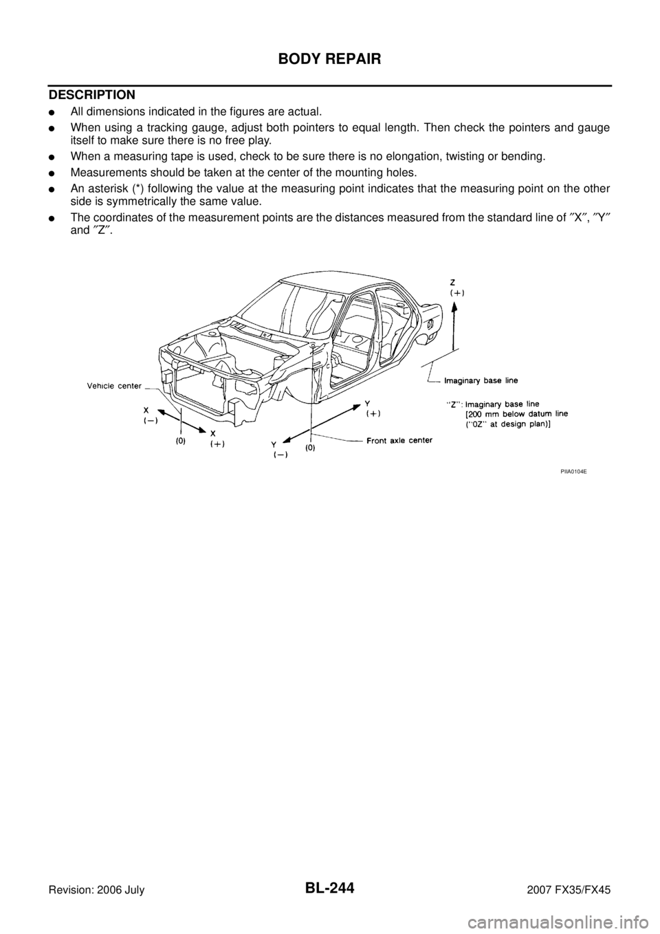
DESCRIPTION
�All dimensions indicated in the figures are actual.
�When using a tracking gauge, adjust both pointers to equal length. Then check the pointers and gauge
itself to make sure there is no free play.
�When a measuring tape is used, check to be sure there is no elongation, twisting or bending.
�Measurements should be taken at the center of the mounting holes.
�An asterisk (*) following the value at the measuring point indicates that the measuring point on the other
side is symmetrically the same value.
�The coordinates of the measurement points are the distances measured from the standard line of ″X ″, ″Y ″
and ″Z ″.
PIIA0104E
Page 1102 of 4366
BR-8
BRAKE PEDAL
Revision: 2006 July 2007 FX35/FX45
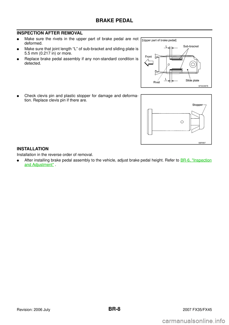
INSPECTION AFTER REMOVAL
�Make sure the rivets in the upper part of brake pedal are not
deformed.
�Make sure that joint length “L” of sub-bracket and sliding plate is
5.5 mm (0.217 in) or more.
�Replace brake pedal assembly if any non-standard condition is
detected.
�Check clevis pin and plastic stopper for damage and deforma-
tion. Replace clevis pin if there are.
INSTALLATION
Installation in the reverse order of removal.
�After installing brake pedal assembly to the vehicle, adjust brake pedal height. Refer to BR-6, "Inspection
and Adjustment" .
SFIA2487E
SBR997
.
CAUTION:
Be careful not to damage con")