Page 188 of 331

Your dealer has Honda accessories
that allow you to personalize your
vehicle. These accessories have
been designed and approved for your
vehicle, and are covered by warranty.
Modifying
your vehicle, or installing
some non-Honda accessories, can
make it unsafe. Before you make any
modifications or add any accessories,
be sure to read the following
info rmation.
Al though non-Honda accessories
may fit on your vehicle, they may not
meet factory specifications, and
could adversely affect your vehicle’s
handling and stability. When
properly installed, cellular
phones, alarms, two-way radios, and
low-powered audio systems should
not interfere with your vehicle’s
computer controlled systems, such
as your airbags and anti-lock brakes.
Befo re installing any accesso ry:
Make sure the accessory does not
obscure any lights, or interfere
with proper vehicle operation or
performance.
Be sure electronic accessories do
not overload electrical circuits
(see page ) or interfere with
the proper operation of your
vehicle.
If
you install a truck cap, be sure it is
properly installed and does not
exceed your vehicle’s load limits (see
page ). 187 291
A ccessories
A ccessories and Modif ications
Your vehicle should not be used to
carry a slide-in camper.
184
Improper accessories or
modifications can affect your
vehicle’s handling, stability, and
performance, and cause a
crash in which you can be hurt
or killed.
Follow all instructions in this
owner’s manual regarding
accessories and modifications.
Page 195 of 331
The cargo net can be used to hold
lightweight items in the pickup bed.
Secure all items properly. The net
may not prevent heavy items f rom
beingthrownoutwardinacrashora
sudden stop.The cargo cover can be used to
cover the cargo area on the pickup
bed.
Your vehicle’s pickup bed has a rust
resistant surf ace. To repair small
chips and scratches in the bed, a
repair kit is available f rom your
dealer. More extensive damage
should be repaired by your dealer.
To avoid problems with the bed
surf ace and the In-Bed Trunk lid, do
not use spray-in bed liner products.
Carrying Cargo
Optional Cargo Net
Optional Cargo Cover
Pickup Bed Repair
Bef ore Driving
191
Page 199 of 331

Youshoulddothefollowingchecks
and adjustmen ts before you drive
your vehicle.
Make sure all windows, mirrors,
and outside lights are clean and
unobstructed. Remove frost, snow,
or ice.
Check that the hood is fully closed.
Check that the tailgate is fully
closed when it is not used as an
exte nded pickup bed.
Vi sually check the tires. If a tire
looks low, use a gauge to check its
pressure.
Check that any items you may be
carrying are stored properly or
fastened down securely. Check
the adjustment of the
inside and outside mirrors (see
page ).
Check the steering wheel
ad justment (see page ).
Make sure the doors and In-Bed
Trunk are securely closed and
locked.
Fasten your seat belt. Check that
your passengers have fastened
their seat belts (see page ).
Wh en you start the engine, check
the gauges and indicato rs in the
instrument panel (see page ).
Check the seat adjustment (see
pages and ).
1.
2.
3.
4.
5.
6.
8. 7.
9.
10.
11. 14
110
79
59
98 100
Preparing to Drive
Driving
195
Page 207 of 331

To get unstuck, apply light pressure
to the accelerator pedal. Do not spin
the f ront tires f or more than a f ew
seconds. Because of the amount of
torque applied to the rear tires, they
should not spin. This is normal. If
you are not able to move the vehicle,
stop and reverse direction.
If you become stuck, you can
activatetheVTM-4bypressingthe
VTM-4 LOCK button while in f irst
(1), second (2), or reverse (R) gear
below18mph(30km/h).Thismode
overrides the auto system to send
maximum torque to the rear axle.
This mode is only intended f or
intermittent use at low speed to free
your vehicle if it becomes stuck or
when you encounter a steep grade
with one wheel on a slippery surf ace.
Generally, you should f irst allow the
auto mode to operate to adjust for
the available traction conditions.
The vehicle speed must be below
18 mph (30 km/h).
Move the shift lever to first (1),
second (2), or reverse (R) gear. Press the VTM-4 LOCK button.
The indicator in the button comes
on.
Your vehicle is equipped with a
variable torque management
4-wheel-drive system (VTM-4) that
distributes engine torque to the
appropriate drive axle depending on
the available traction conditions. The
system is completely automatic,
always active, and does not require
any driver interaction. 1.
2.3.
CONT INUED
To Engage the VTM-4 Lock:
VTM-4 System
Driving
203
VTM-4 LOCK BUTTON
Do not use the VTM-4 LOCK button on
dry, paved roads. Driving on dry,
paved roads with VTM-4 Lock ON may
damage the rear dif f erential when
making a turn. Strange noise and
vibration can also result.
Page 210 of 331
 and the windows are
closed.
Turn of f the lights.
Place any packages, valuables, etc.
in the cargo area in your vehicle or
the In-Bed Trunk, or take them
with you.")
Make sure the moonroof (if
equipped) and the windows are
closed.
Turn of f the lights.
Place any packages, valuables, etc.
in the cargo area in your vehicle or
the In-Bed Trunk, or take them
with you.
Lock the doors.
Check the indicator on the driver’s
door to verify that the security
system is set.
Never park over dry leaves, tall
grass, or other f lammable
materials. The hot three way
catalytic converter could cause
these materials to catch on fire.
Set the parking brake bef ore you put
the transmission in Park. This keeps
the vehicle from moving and putting
pressure on the parking mechanism
in the transmission. Always use the parking brake when
you park your vehicle. Make sure
the parking brake is set f irmly, or
your vehicle may roll if it is parked
on an incline.
On vehicles with security system
As required by the FCC:
This device complies with Part 15 of theFCC rules. Operation is subject to thef ollowing two conditions: (1) This devicemay not cause harmf ul interf erence, and(2) this device must accept anyinterf erence received, includinginterf erence that may cause undesiredoperation.
Changes or modif ications not expresslyapproved by the party responsible f orcompliance could void the user’sauthority to operate the equipment.
This device complies with IndustryCanada Standard RSS-210.Operation is subject to the f ollowing twoconditions: (1) this device may not causeinterf erence, and (2) this device mustaccept any interf erence that may causeundesired operation of the device.
Parking T ips
Parking
Tire Pressure Monitoring System (TPMS), Parking
206
Page 211 of 331

If the brake pads need replacing, you
will hear a distinctive, metallic
screeching sound when you apply
the brake pedal. If you do not have
the brake pads replaced, they will
screech all the time. It is normal f or
the brakes to occasionally squeal or
squeak when you apply them. The hydraulic system that operates
the brakes has two separate circuits.
Each circuit works diagonally across
the vehicle (the lef t-f ront brake is
connected with the right-rear brake,
etc.). If one circuit should develop a
problem, you will still have braking
at two wheels.
Your vehicle is equipped with disc
brakes at all f our wheels. A power
assist helps reduce the ef f ort needed
on the brake pedal. The anti-lock
brake system (ABS) helps you retain
steering control when braking very
hard.
Constant application of the brakes
when going down a long hill builds
up heat and reduces their ef f ective-
ness. Use the engine to assist the
brakes by taking your f oot of f the
accelerator and downshif ting to a
lower gear.
If the vehicle is f acing uphill, turn
the front wheels away from the
curb, and set the parking brake.
If the vehicle is f acing downhill,
turn the front wheels toward the
curb, and set the parking brake.
Make sure the parking brake is
f ully released bef ore driving away.
Driving with the parking brake
partially set can overheat or
damage the rear brakes.
Resting your f oot on the pedal keeps
the brakes applied lightly, builds up
heat, and reduces their ef f ectiveness.
It also keeps your brake lights on all
the time, conf using drivers behind
you. Check the brakes after driving
through deep water. Apply the
brakes moderately to see if they f eel
normal. If not, apply them gently and
f requently until they do. Be extra
cautious and alert in your driving.
Braking System Design
Braking System
Brake Pad Wear Indicators
Parking, Braking System
Driving
207
Page 223 of 331
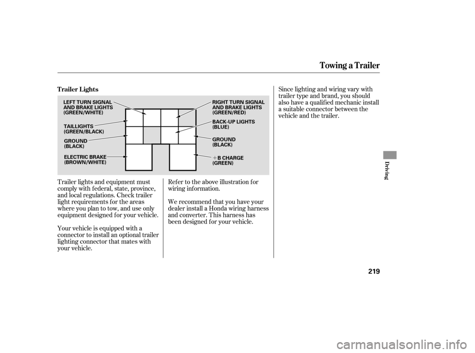
�´
Trailer lights and equipment must
comply with f ederal, state, province,
and local regulations. Check trailer
light requirements f or the areas
where you plan to tow, and use only
equipment designed f or your vehicle.Since lighting and wiring vary with
trailer type and brand, you should
also have a qualif ied mechanic install
a suitable connector between the
vehicle and the trailer.
Your vehicle is equipped with a
connector to install an optional trailer
lighting connector that mates with
your vehicle. We recommend that you have your
dealer install a Honda wiring harness
and converter. This harness has
been designed f or your vehicle. Ref er to the above illustration f or
wiring information.
Trailer Lights
Towing a Trailer
Driving
219
GROUND
(BLACK)
LEFT TURN SIGNAL
AND BRAKE LIGHTS
(GREEN/WHITE)
TAILLIGHTS
(GREEN/BLACK)
ELECTRIC BRAKE
(BROWN/WHITE) RIGHT TURN SIGNAL
AND BRAKE LIGHTS
(GREEN/RED)
BACK-UP LIGHTS
(BLUE)
GROUND
(BLACK)
B CHARGE
(GREEN)
Page 225 of 331
CONT INUED
The 7-pin trailer connector is needed
f or the trailer lights. To connect the
connector, do this:Make sure the connector and the
socketarefreeof dirt,moisture,
or other f oreign material.
Open the socket lid by pulling it up. Insert the connector securely into
the socket.
Hook the retaining tab on the
inner side of the lid against the
retaining tab of the connector to
prevent disconnection during
operation.
Remove the socket cover, and
attach it securely over the socket.
Insert the connector into the
socket securely to prevent
disconnection during operation.
The 4-pin trailer connector is also
needed f or the trailer lights. To
connect the connector, do this:
1. 1.
2. 3.
4.
2.
Towing a Trailer
Connect ing t he T railer Connect ors
Driving
221
7-PIN TRAILER CONNECTOR SOCKETRETAINING
TAB
RETAINING
TAB
LID
4-PIN TRAILER CONNECTORSOCKET COVER
7-PIN TRAILER
CONNECTOR 4-PIN TRAILER
CONNECTOR